As you may understand, the size of the most of RF components is inversally proportional to the frequency of the operating frequency. In other words, the size of the RF components gets smaller as the operating frequency increases. Antenna elements (single antenna) would be the components that best complies to this rule.
Considering very high operating frequency of 6G, we would easily guess that the size of an antenna elements would be very small.
The size of single dipole antenna element on PCB working at 1 Thz can be only 150 um and the size of graphene antenna (or any other antenna made of plasmonic materials) can be even smaller - e.g, 1umlong /10nm wide (Ref [1]).
This small size can be beneficial in that it can be applicable for on-chip communication or wearable communication but the small aperture would be limiting factor in terms of transmission power.
To overcome the power limi due to small aperture, multiple antenna elements in an array format is likely to be the one being used in real communication system (same logic as we use massive MIMO in 5G).
- metallic antenna (like PCB antenna) arrays utilized in conjunction with electronic front-ends have been demonstrated at frequencies under 300 GHz with up to 16 controllable elements. (Ref [1]).
- in conjunction with plasmonic front-ends, very large graphene-based plasmonic antenna arrays with up to 1,024 elements have been proposed (this may be called as ultra-massive MIMO) (Ref [1]).
Thanks to the very small size of the antenna elements in the 6G frequency range enables huge number of antenna elements (array, e.g, 1024, 4096 or higher) can be integrated into Tx and Rx chipset. With this number of antenna elements, it would be easier to more sophisticated / accurate MU MIMO.
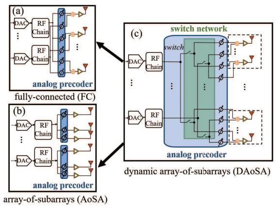
As in 5G FR2, it is highly likely that Hybrid Beamforming will be used in 6G as well. For the analog precoder part in the hybrid beamforming, usually two different types are used : Fully-Connected or Array of Subarrays (I think the array of subarray type is more commonly used). In 6G with utilizing much larger number of antenna elements, we can think of another types for the analog precoder part called dynamic array-of-subarrays which can change the configuration of the sub-arrays dinamically as illustrated below.
Source : Terahertz Band Communication: An Old Problem Revisited and Research Directions for the Next Decade
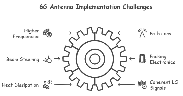
Implementation Challenges
Implementing 6G antennas comes with many challenges due to the use of THz frequencies, which require new materials and advanced designs. Unlike 5G, where phased array antennas work well, 6G antennas need much smaller elements because of the shorter wavelengths. This makes beam steering more difficult and requires precise control of each element. THz signals also experience high path loss, meaning they weaken quickly as they travel. To overcome this, 6G antennas must have high gain and strong directionality, but obstacles like walls and buildings can still cause interference. Another major challenge is fitting thousands of tiny antenna elements into a very small space. These elements need to be connected to RF electronics, but packing them closely together creates heat dissipation problems, making continuous operation difficult. Since THz transceivers are not very efficient, they consume a lot of power, which increases heat issues. Additionally, generating and distributing a stable and low-noise local oscillator (LO) signal across multiple chips is tricky. Using many PLLs can help, but it also affects beam performance. To make 6G antennas work, researchers must find new materials, improve circuit design, manage heat better, and develop new signal processing methods.
- In 5G, beam steering is typically achieved using phased array antennas, which consist of multiple antenna elements that can be controlled individually to steer the beam in a particular direction. The wavelength of 5G signals is relatively long compared to THz signals, which means that the spacing between antenna elements can be larger. This makes it easier to control the phase and amplitude of each element accurately.
- In THzCom, the wavelength of THz signals is much shorter than in 5G, which means that the spacing between antenna elements must be much smaller. This requires more precise control over the phase and amplitude of each element to achieve accurate beam steering. In addition, THz signals are more susceptible to attenuation and interference from obstacles such as walls and buildings due to their shorter wavelengths. This means that beam steering must be even more precise in order to avoid these obstacles.
Operating at 500 GHz with 10 000 antenna elements brings the size of the required array down to just 3 cm 3 cm, with the elements spaced half-wavelength apart, i.e., 0.3 mm. The RF electronics must have the same size to minimize the length of THz interconnects, which is a major research challenge. Each chip must then feature multiple transceivers. For instance, a 3 mm 3 mm chip can have 100 transceivers, and 100 such chips need to be used in the 10 000 antennaelement arrays. The antennas may be implemented onor off-chip, where on-chip antennas generally have less efficiency, yet they eliminate the loss in chip-to-carrier interfaces
Since THz transceivers will have low efficiency, the area for heat dissipation will be very small. If each transceiver consumes 100 mW, the total power consumption of the array becomes 1 kW, having major implications on the system not being able to be continuously active. If heat dissipation becomes too problematic, more sparse arrays may have to be considered for, e.g., using compressive sensing-based array thinning principles with more than half wavelength element spacing. However, this would cause side lobes that need to be managed, which, in turn, may pose constraints on spectrum sharing with existing or adjacent services.
The generation of a central 500-GHz signal to be distributed to all transceivers, perhaps 100, on a chip seems impractical, as it would consume very large power in the buffers. As such, a more distributed solution with local phase-locked loops (PLLs) is more appealing since a lower frequency reference can then be distributed over the chip. The phase noise of different PLLs will then be noncorrelated; using multiple PLL signals together can achieve low noise beams. On the other hand, doing this results in depth reduction when forming notches, limiting the performance of multiple simultaneous beams. To this end, there is a tradeoff in choosing the number of PLLs. Nonetheless, given the high power of LO signal distribution, a large number of PLLs seems favorable. This is further pronounced by the difficulty of reaching high resonator energy in a single oscillator at such high frequencies, making it attractive to increase the total energy by increasing the number of oscillators in the system. Using a large number of PLLs also provides LO beamforming possibilities, as the PLL phase can accurately be controlled. Regardless of LO architecture, another challenge is frequency tuning of oscillators since the quality factor of variable reactances (varactors) is inversely proportional to the operating frequency. As such, at THz frequencies, other tuning mechanisms should be investigated, such as using resistance for tuning
How to overcome challenges ?
Now let's think of how to overcome the challenges listed above ? We don't have any clear solution yet. Even if we have some candidate solutions now, we don't know if that solution will be adopted to real implementation of 6G. For now, take this section as just a start of brainstorming and I will keep updating this as I learn further.
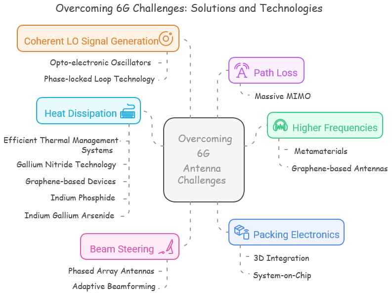
- Metamaterials: These artificially engineered materials exhibit unique properties that can help design antennas with better performance at higher frequencies.
- Graphene-based antennas: Graphene has excellent electrical and thermal properties, making it suitable for designing compact and efficient antennas for higher frequency operation.
- Massive MIMO : Utilizing a large number of antennas at both the transmitter and receiver to improve signal strength and reduce path loss.
- Phased array antennas: These antennas use an array of elements to create a steerable beam that can be controlled electronically, improving coverage and reducing interference.
- Adaptive beamforming: Using signal processing techniques to dynamically adjust the antenna pattern, optimizing coverage and minimizing interference.
- 3D integration: Stacking electronic components vertically, instead of horizontally, can reduce the size of components and enable tighter packing.
- System-on-Chip (SoC) technology: Integrating multiple electronic components into a single chip can reduce the overall size and complexity of the system.
- Efficient thermal management systems: Implementing advanced cooling techniques, such as heat pipes or vapor chambers, can help to dissipate heat effectively.
- Chosing Proper materials with better heat property or less heat generation with maintaining high enough performance within the range of 6G candidate frequency spectrum.
- Gallium Nitride (GaN) technology: GaN-based electronics have a higher thermal conductivity and can operate at higher temperatures compared to traditional silicon-based devices, allowing for better heat dissipation. // It is still questionable that GaN can perform well in sub Thz to Thz. Just wait and see since the technology is improving.
- Graphene-based devices: Graphene has outstanding thermal conductivity which is significantly higher than that of most semiconductors, including GaN, InP, and InGaAs. This exceptional thermal conductivity makes graphene-based devices well-suited for heat dissipation in high-frequency applications. Furthermore, graphene's high electron mobility allows for efficient device operation, potentially reducing power consumption and heat generation.
- Indium Phosphide (InP): InP has a higher thermal conductivity compared to silicon, but it is lower than that of GaN. While InP may not offer the same level of heat dissipation performance as GaN or graphene, its high electron mobility and suitability for high-frequency applications make it a promising candidate for sub-THz and THz devices.
- Indium Gallium Arsenide (InGaAs): InGaAs has a thermal conductivity, which is lower than that of GaN and InP. However, it offers higher electron mobility compared to GaN and silicon, which could lead to better overall device performance in high-frequency applications. The lower thermal conductivity of InGaAs might be a challenge for heat dissipation, but by implementing proper thermal management techniques, it can still be a viable option for high-frequency applications.
- Opto-electronic oscillators (OEOs): These oscillators use optical signals to generate high-frequency, low-noise LO signals, improving the overall performance of the system.
- Phase-locked loop (PLL) technology: PLLs can help generate stable, low-noise LO signals by synchronizing an oscillator's frequency with that of a reference signal.
Reference
[1] Terahertz Band Communication: An Old Problem Revisited and Research Directions for the Next Decade
[2] Hera-X : Deliverable D2.1 Towards Tbps Communications in 6G: Use Cases and Gap Analysis
[3] ETSI GR mWT 022 V1.1.1 (2021-04)
[4] WHITE PAPER ON RF ENABLING 6G OPPORTUNITIES AND CHALLENGES FROM TECHNOLOGY TO SPECTRUM
[6] An Overview of Terahertz Antennas
[7] 6G Wireless Systems: Vision,Requirements, Challenges,Insights, and Opportunities - ResearchGate
[8] NEC Develops 150 GHz Antenna-on-Chip Transmitter IC chip for Beyond 5G/6G Radio Equipment - everythingRF (2023)
YouTube
- RF System Design towards 6G - IEEE Microwave Theory and Technology Society (May 2024)
- 300 GHz Receiver Font-end: Design Perspective - IEEE Microwave Theory and Technology Society (May 2024)
- Antennas, Materials, and Packaging for 6G Applications - IEEE Microwave Theory and Technology Society (May 2024)
- Foundations and Operating Principles of RF Power Amplification - IEEE Microwave Theory and Technology Society (May 2024)
- Broadband Matching Synthesis for RFPA - IEEE Microwave Theory and Technology Society (May 2024)
- 6G Talks - Innovations in Antenna Technology for Future Communications with Jack Soh - 6G Flagship(May 2024)