Bluetooth is a wireless technology fundamental to modern communication, enabling devices to exchange data over short distances. In this note, we will look into the protocol aspect of the bluetooth. The protocol harmonizes diverse electronics, making wire-free interactions a global standard. It's a cornerstone of the Internet of Things, linking gadgets from headphones to heart monitors with secure, low-energy connectivity. As Bluetooth evolves, it continues to broaden the horizons of seamless, ubiquitous connectivity.
This note covers Bluetooth BR/EDR, which is often called Bluetooth Classic. The inquiry, page, Sniff and Hold procedures below all belong to BR/EDR. Bluetooth Low Energy finds and connects devices in a different way, so it is not covered here. One more point before we start. The figures and the capture use the role names master and slave. Core Specification v5.3 replaced a set of terms, and the current text says Central and Peripheral for these two roles. I keep master and slave in this note, so that the text matches the figures and the log.
- Overall State Transition
- Overall Protocol Sequence
- How does this capture compare with the current Core Specification ?
- Reference
Overall State Transition
Overall state flow of bluetooth communication is as follows. When you see this kind of circular state diagram, you'd better select one of the starting point and end point. Otherwise, you will keep cycling through the states and your eye ball would be spinning endlessly -:).
For example, I just picket "Stand by" as the first point and "Tx/Rx" as the end point and follow through the path marked in red arrows.
As you turn on a bluetooth device, it would be into stand by mode and start "inquire". (This is like broadcasting a message to all direction saying "Is there any one listening to me ? If there is, let me know your address". Through this process, the device may get the response from multiple device. If it finds any device it want to connect, it sends Paging message to the device saying "I want to get connected to you". If it gets the acceptance from the other party, the both party gets into connected mode via a complicated steps which will be described next section.
Once in connected mode, both party can transmit and receive data. But what if there is no data to transmit or recieve for a long time ? It they stay awake during that period, it would waste a lot of battery power. To reduce the waste of the battery life, bluetooth support three levels of energy saving mode, called Sniff, Hold, Park.
In Sniff mode, the device still maintain the synchronization with piconet (network between bluetooth devices) but the Tx/Rx cycle gets reduced. This cycle is called "Sniff Interval" and this interval is programmable and depends on application.
In Hold mode, only the internal clock in the device is running. So in this mode, data transfer is not possible but if there is need for data transfer, it can switch to Active mode very quickly. This HOLD mode can be initiated ether Master or Slave.
In Park mode, the device still maintains the synchronization with piconet (network between bluetooth devices) but it does not transmit/recieve any data.. the device even release its MAC address. It just periodically wake up to listen to Master. If it gets any signal from Master requesting data transaction, it has to go through connection process again. It would take a little longer time/process to recover the connection but it saves energy the most.
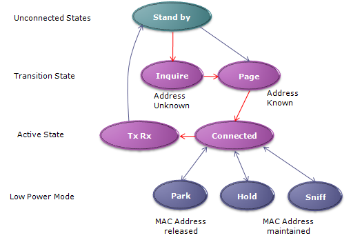
Figure 1. Bluetooth BR/EDR state flow. The red arrows mark the usual path from Stand by through Inquire, Page and Connected to Tx Rx, and the three low power modes are all entered from the Connected state.
Two labels in Figure 1 need a note against the current specification. The first is Park. Core Specification v5.0 removed the Park state, and the baseband section that used to describe it is now marked as no longer used. So a device built to the current specification never enters the Park box. Sniff and Hold are the two low power modes left for an ACL link.
The second is the label MAC Address under the low power modes. It does not mean the 48 bit BD_ADDR. The BD_ADDR is the permanent address of the device, and no low power mode releases it. The address in question is the 3 bit logical transport address, LT_ADDR. The master gives this address to the slave in the FHS packet during paging, and the slave uses it as its address inside the piconet. The baseband specification states that the slave keeps its LT_ADDR during Hold mode.
Park is gone from the current specification : Core v5.0 removed it, so Sniff and Hold are the low power modes to look for in a current BR/EDR log.Sniff keeps the link and reduces listening : the slave listens only from sniff anchor points spaced Tsniff apart, and the master transmits to it only in those slots.Hold stops ACL traffic for an agreed time : the two sides agree the duration first, and the slave wakes up when the holdTO timer expires. SCO and eSCO slots still run during Hold, so only ACL data stops.The address kept in Sniff and Hold is the LT_ADDR : the BD_ADDR never changes, so the MAC Address labels in the diagram refer to the piconet address.
Overall Protocol Sequence
The sequence has three stages, and each stage answers a different question. Inquiry finds out which devices are nearby, and it learns their BD_ADDR and clock. Paging uses that address and clock estimate to reach one chosen device. It also hands the master clock over to the slave. The connection stage then confirms that both sides follow the same hopping sequence. The step numbers in the diagram below are the numbers used in the three sub-sections. Overall protocol sequence from the Inquiry to connection setup can be illustrated as follows:
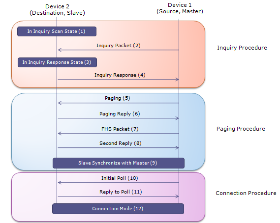
Figure 2. Inquiry, paging and connection message flow. Only the FHS packet of step 7 carries the master clock to the slave, and the slave switches to that clock in step 9.
Every step in this sequence runs on the baseband slot grid. One slot is 625 microseconds, and the master transmits in even slots. The native clock ticks every 312.5 microseconds, so one slot is two clock ticks. Keep these two numbers in mind, because the reply times in the sub-sections below are written in them.
Inquiry Procedure
Device 1 (the source or master) and Device 2 (the destination or slave). Here's how timing synchronization occurs during this process: this whole process is designed to minimize the need for precise, long-term clock synchronization between devices while still allowing them to establish a connection efficiently. The devices only need to have sufficiently synchronized clocks for the duration of the inquiry and page processes. Once a connection is established, more robust synchronization mechanisms, such as adaptive frequency hopping, take over to maintain synchronization.
Device 2 enters an "Inquiry Scan State," where it listens for inquiry packets. It does this periodically based on its internal clock, following a schedule of scan windows (when it listens) and intervals (the time between scan windows).
Device 1, which is in an "Inquiry State," sends out inquiry packets on a set sequence of hop frequencies defined for the inquiry process. It does so according to its internal clock, which defines the timing of when these packets are sent.
When Device 2 receives an inquiry packet during its scan window, it will switch to the "Inquiry Response State." In this state, Device 2 prepares an inquiry response packet that includes timing information, such as its native clock and Bluetooth device address (BD_ADDR).
Device 2 sends the inquiry response packet back to Device 1. This response must be timed precisely to fall within a window when Device 1 expects to receive responses. The timing of this response is critical and is based on the time at which the inquiry packet from Device 1 arrived. The inquiry packet itself is a short ID packet, and it carries no information about Device 1.
- The timing synchronization in this process involves using the native clocks of both devices. The clocks are not directly shared or synchronized over the air; instead, they maintain their own timing. However, they use the timing information exchanged during the inquiry and response to facilitate a successful connection setup.
- When Device 1 receives the inquiry response from Device 2, it can calculate the clock offset between the two devices. This calculation is based on the timing of the inquiry response relative to its own clock and the expected timing pattern of responses.
- This clock offset will then be used during the subsequent page (connection) process, where Device 1 will adjust its frequency hopping sequence to match that of Device 2, thus achieving synchronization necessary for a successful communication link.
The inquiry response packet in step [4] is an FHS packet. Device 2 sends it 625 microseconds after the inquiry packet it received. If Device 2 has extended inquiry response data, it sends that packet 1250 microseconds after the start of the FHS packet, on the same frequency. The inquiry hop sequence of 32 frequencies is always derived from the general inquiry access code, GIAC, whose LAP is 0x9E8B33. This holds even when a dedicated inquiry access code is used. You will see the same LAP in step 1 of Example 01 below.
The scan side has two numbers of its own. The default inquiry scan window is 11.25 ms. The inquiry scan interval, which is the time between two scan windows, must be 2.56 s or less. So a discoverable device listens for only a small part of the time. This is why the inquiring device keeps repeating its inquiry packet over many frequencies.
Paging Procedure
This is the process that follows the initial inquiry and device discovery. It's used to establish a communication link between a master device and a slave device. During the entire paging procedure, timing synchronization is crucial. The devices must exchange messages and acknowledge them within specific time slots. The FHS packet is especially important for synchronization as it allows the slave to adjust its timing to match the master's clock. This ensures that when the master and slave start their frequency hopping sequences, they are in sync, allowing for a stable and robust communication link.
The master device, having obtained the address and clock information of the slave device from the inquiry process, sends a paging message. This message is sent on a frequency determined by the slave's device address and its native clock.
The slave device, upon recognizing the paging message addressed to it (since it matches its own address), sends a paging reply to the master. This reply signals to the master that the slave is ready to establish a connection.
After the paging reply, the master sends a Frequency Hop Synchronization (FHS) packet to the slave. This packet contains the master's Bluetooth device address and clock information. The slave uses the information in the FHS packet to synchronize its frequency hopping pattern with the master's clock.
The slave acknowledges the receipt of the FHS packet by sending a second reply to the master. This second reply is the slave's device access code again, so it carries no further information.
The slave adjusts its internal clock using the information provided by the master so that both devices are now synchronized. This involves the slave device working out the offset between the master's clock in the FHS packet and its own native clock, and then following the master's clock.
After this exchange of packets and synchronization, the master and slave devices are now synchronized, and a connection is established. They can now begin communicating using their agreed-upon frequency hopping sequence.
During the entire paging procedure, timing synchronization is crucial. The devices must exchange messages and acknowledge them within specific time slots. The FHS packet is especially important for synchronization as it allows the slave to adjust its timing to match the master's clock. This ensures that when the master and slave start their frequency hopping sequences, they are in sync, allowing for a stable and robust communication link.
Here are the numbers behind the page train in step [5]. The master does not know the exact slave clock, so it sends the page on a train of 16 frequencies around its estimate. There are 32 possible paging frequencies within each 1.28 s interval. Half of them form the A train, and the other half form the B train. The A train is centred on the estimate, and the clock offset learned in the inquiry is what makes that estimate good.
Two timers bound the exchange. The slave waits for the FHS packet only until pagerespTO expires, and then it returns to page scan. The master retransmits the FHS packet with an updated clock until the second reply of step [8] arrives, or until pagerespTO expires. The page scan repetition mode tells the master how often the slave scans. In mode R1, the page scan interval is 1.28 s or less.
Connection Procedure
After the paging procedure, the devices enter the connection procedure to finalize the establishment of a communication link. During the connection procedure, timing synchronization ensures that the master and slave are still in sync following the frequency hopping sequence established during the paging process. This synchronization is critical for maintaining a robust communication link where data packets are transferred without error and in the correct order.
The master device sends an initial poll packet to the slave device. This poll packet is used to confirm that the slave device is ready and listening for communications from the master. It’s a way for the master to verify that the connection is still active after the paging process.
The slave device responds to the poll packet from the master, confirming its presence and readiness to communicate. This reply is essential as it signifies that the slave device is in range and has successfully synchronized its clock with the master’s clock, based on the previous paging process.
Once the initial polling and response have confirmed that both devices are present and synchronized, they enter the connection mode. In this mode, the two devices have an established communication link and will begin their normal operations for data transfer.
The connection mode may involve different states such as active mode, where devices can actively send and receive data; sniff mode, where the device listens for transmissions at reduced power to save energy; hold mode, where the connection is maintained without active data transfer; and park mode, where the slave device is inactive but still synchronized to the master.
The first packet on the new channel is always a POLL packet from the master. The slave may answer with a NULL, DM1 or DH1 packet. If either packet is missed within newconnectionTO slots after the FHS acknowledgment, the master returns to Page and the slave returns to Page Scan. The park mode in step [12] is the Park state of Figure 1, which Core v5.0 removed.
Example 01
Following is one example bluetooth protocl log from wiki.wireshark.org - Bluetooth1.cap . Just go through overall sequence first and dig into the detailed parameters in each of the message as it interests you.
This log is taken at the HCI, which is the interface between the host and the Bluetooth controller. So it never shows the ID, FHS and POLL packets of Figure 2. Those packets stay inside the controller. What the log does show is the host asking for each procedure with an HCI command, and the controller reporting the result with an HCI event. Step 1 starts the inquiry of Figure 2. Steps 8 to 22 are the result of a page that the other device started, so this device becomes the slave.
Let's read the table in six groups.
Steps 1 to 4 find one device : the Inquiry command uses LAP 0x9e8b33, which is the GIAC. Inquiry Length 16 means at most 16 x 1.28 s = 20.48 s, and Num Responses 0 means an unlimited number of responses. One phone answers, with BD_ADDR 00:0e:6d:07:2e:fa and a clock offset of 0x42dd.Steps 5 to 7 are a name request that fails : the controller has to page the phone to read its name, and the event ends with status 0x04, Page Timeout. The request carries Clock_Offset_Valid_Flag false, so the controller paged without the offset that step 3 reported. The log does not show why the page failed.Steps 8 to 14 are an incoming connection that fails : the phone pages this device, the host accepts and stays slave, and legacy PIN pairing runs with PIN 1234. Connect Complete then reports status 0x05, Authentication Failure, for handle 0x0029.Steps 15 to 22 are the second attempt, and it succeeds : the same exchange runs again, and this time Link Key Notification delivers a Combination Key. Connect Complete reports success for handle 0x002a, with encryption on.Steps 23 to 30 configure the link : the host sets the link policy, the controller reports page scan mode R1, and the host enables all DM and DH packet types. The controller answers with Max Slots Change to 5 slots and then Connection Packet Type Changed.Steps 31 to 35 end the connection : two more name requests go out. The second name request ends with status 0x13, Remote User Terminated Connection, and Disconnect Complete reports the same reason for handle 0x002a.
Three numbers help when you read the dumps. The first is the opcode, which is OGF x 1024 + OCF. For example, Remote Name Request is OGF 0x01 and OCF 0x0019, so its opcode is 0x0419. Write Link Policy Settings is OGF 0x02 and OCF 0x000d, so its opcode is 0x080d.
The second is Parameter Total Length, which counts only the parameter octets. The Inquiry command has 3 + 1 + 1 = 5 octets for LAP, Inquiry Length and Num Responses. Remote Name Req Complete has 1 + 6 + 248 = 255 octets. The name field is always 248 octets long, even when it is empty as in steps 7 and 34.
The third is Clock Offset. It holds bits 16 to 2 of the clock difference, so one unit is 4 clock ticks, or 1.25 ms. The value 0x42dd in step 3 is 17117 units, which is 21396.25 ms. The 15 bit field therefore wraps every 32768 x 1.25 ms = 40.96 s.
Decoded HCI packets,
Bluetooth HCI H4
    [Direction: Sent (0x00)]
    HCI Packet Type: HCI Command (0x01)
Bluetooth HCI Command - Inquiry
    Command Opcode: Inquiry (0x0401)
        0000 01.. .... .... = ogf: Link Control Commands (0x0001)
        .... ..00 0000 0001 = ocf: 0x0001
    Parameter Total Length: 5
    LAP: 0x9e8b33
    Inquiry Length: 16
    Num Responses: 0
Bluetooth HCI H4
    [Direction: Rcvd (0x01)]
    HCI Packet Type: HCI Event (0x04)
Bluetooth HCI Event - Command Status
    Event Code: Command Status (0x0f)
    Parameter Total Length: 4
    Status: Pending (0x00)
    Number of Allowed Command Packets: 1
    Command Opcode: Inquiry (0x0401)
Bluetooth HCI H4
    [Direction: Rcvd (0x01)]
    HCI Packet Type: HCI Event (0x04)
Bluetooth HCI Event - Inquiry Result
    Event Code: Inquiry Result (0x02)
    Parameter Total Length: 15
    Number of responses: 1
    BD_ADDR:000e:6d:072efa (MurataMa_07:2e:fa)
    Page Scan Repetition Mode: R1 (0x01)
    Page Scan Period Mode: P0 (0x00)
    Page Scan Mode: Mandatory Page Scan Mode (0x00)
    Class of Device: 0x420204 (Phone - services: Telephony, Networking)
    .100 0010 1101 1101 = Clock Offset: 0x42dd
Bluetooth HCI H4
    [Direction: Rcvd (0x01)]
    HCI Packet Type: HCI Event (0x04)
Bluetooth HCI Event - Inquiry Complete
    Event Code: Inquiry Complete (0x01)
    Parameter Total Length: 1
    Status: Success (0x00)
Bluetooth HCI H4
    [Direction: Sent (0x00)]
    HCI Packet Type: HCI Command (0x01)
Bluetooth HCI Command - Remote Name Request
    Command Opcode: Remote Name Request (0x0419)
        0000 01.. .... .... = ogf: Link Control Commands (0x0001)
        .... ..00 0001 1001 = ocf: 0x0019
    Parameter Total Length: 10
    BD_ADDR:000e:6d:072efa (MurataMa_07:2e:fa)
    Page Scan Repetition Mode: R1 (0x01)
    Page Scan Mode: Mandatory Page Scan Mode (0x00)
    .000 0000 0000 0000 = Clock Offset: 0x0000 (0 ms)
    0... .... .... .... = Clock_Offset_Valid_Flag: false (0)
(6) Command Status (Remote Name Request)
Bluetooth HCI H4
    [Direction: Rcvd (0x01)]
    HCI Packet Type: HCI Event (0x04)
Bluetooth HCI Event - Command Status
    Event Code: Command Status (0x0f)
    Parameter Total Length: 4
    Status: Pending (0x00)
    Number of Allowed Command Packets: 1
    Command Opcode: Remote Name Request (0x0419)
Bluetooth HCI H4
    [Direction: Rcvd (0x01)]
    HCI Packet Type: HCI Event (0x04)
Bluetooth HCI Event - Remote Name Req Complete
    Event Code: Remote Name Req Complete (0x07)
    Parameter Total Length: 255
    Status: Page Timeout (0x04)
    BD_ADDR:000e:6d:072efa (MurataMa_07:2e:fa)
    Remote Name:
Bluetooth HCI H4
    [Direction: Rcvd (0x01)]
    HCI Packet Type: HCI Event (0x04)
Bluetooth HCI Event - Connect Request
    Event Code: Connect Request (0x04)
    Parameter Total Length: 10
    BD_ADDR:000e:6d:072efa (MurataMa_07:2e:fa)
    Class of Device: 0x6a0204 (Phone - services: Telephony, Audio, Capturing, Networking)
    Link Type: ACL connection (Data Channels) (0x01)
Bluetooth HCI H4
    [Direction: Sent (0x00)]
    HCI Packet Type: HCI Command (0x01)
Bluetooth HCI Command - Accept Connection Request
    Command Opcode: Accept Connection Request (0x0409)
        0000 01.. .... .... = ogf: Link Control Commands (0x0001)
        .... ..00 0000 1001 = ocf: 0x0009
    Parameter Total Length: 7
    BD_ADDR:000e:6d:072efa (MurataMa_07:2e:fa)
    Role: Remain Slave (0x01)
(10) Command Status (Accept Connection Request)
Bluetooth HCI H4
    [Direction: Rcvd (0x01)]
    HCI Packet Type: HCI Event (0x04)
Bluetooth HCI Event - Command Status
    Event Code: Command Status (0x0f)
    Parameter Total Length: 4
    Status: Pending (0x00)
    Number of Allowed Command Packets: 1
    Command Opcode: Accept Connection Request (0x0409)
Bluetooth HCI H4
    [Direction: Rcvd (0x01)]
    HCI Packet Type: HCI Event (0x04)
Bluetooth HCI Event - PIN Code Request
    Event Code: PIN Code Request (0x16)
    Parameter Total Length: 6
    BD_ADDR:000e:6d:072efa (MurataMa_07:2e:fa)
Bluetooth HCI H4
    [Direction: Sent (0x00)]
    HCI Packet Type: HCI Command (0x01)
Bluetooth HCI Command - PIN Code Request Reply
    Command Opcode: PIN Code Request Reply (0x040d)
        0000 01.. .... .... = ogf: Link Control Commands (0x0001)
        .... ..00 0000 1101 = ocf: 0x000d
    Parameter Total Length: 23
    BD_ADDR:000e:6d:072efa (MurataMa_07:2e:fa)
    PIN Code Length: 4
    PIN Code: 1234
(13) Command Complete (PIN Code Request Reply)
Bluetooth HCI H4
    [Direction: Rcvd (0x01)]
    HCI Packet Type: HCI Event (0x04)
Bluetooth HCI Event - Command Complete
    Event Code: Command Complete (0x0e)
    Parameter Total Length: 10
    Number of Allowed Command Packets: 1
    Command Opcode: PIN Code Request Reply (0x040d)
        0000 01.. .... .... = ogf: Link Control Commands (0x0001)
        .... ..00 0000 1101 = ocf: 0x000d
    Status: Success (0x00)
    BD_ADDR:000e:6d:072efa (MurataMa_07:2e:fa)
Bluetooth HCI H4
    [Direction: Rcvd (0x01)]
    HCI Packet Type: HCI Event (0x04)
Bluetooth HCI Event - Connect Complete
    Event Code: Connect Complete (0x03)
    Parameter Total Length: 11
    Status: Authentication Failure (0x05)
    Connection Handle: 0x0029
    BD_ADDR:000e:6d:072efa (MurataMa_07:2e:fa)
    Link Type: ACL connection (Data Channels) (0x01)
    Encryption Mode: Encryption Disabled (0x00)
Bluetooth HCI H4
    [Direction: Rcvd (0x01)]
    HCI Packet Type: HCI Event (0x04)
Bluetooth HCI Event - Connect Request
    Event Code: Connect Request (0x04)
    Parameter Total Length: 10
    BD_ADDR:000e:6d:072efa (MurataMa_07:2e:fa)
    Class of Device: 0x6a0204 (Phone - services: Telephony, Audio, Capturing, Networking)
    Link Type: ACL connection (Data Channels) (0x01)
(16) Accept Connection Request
Bluetooth HCI H4
    [Direction: Sent (0x00)]
    HCI Packet Type: HCI Command (0x01)
Bluetooth HCI Command - Accept Connection Request
    Command Opcode: Accept Connection Request (0x0409)
        0000 01.. .... .... = ogf: Link Control Commands (0x0001)
        .... ..00 0000 1001 = ocf: 0x0009
    Parameter Total Length: 7
    BD_ADDR:000e:6d:072efa (MurataMa_07:2e:fa)
    Role: Remain Slave (0x01)
(17) Command Status (Accept Connection Request)
Bluetooth HCI H4
    [Direction: Rcvd (0x01)]
    HCI Packet Type: HCI Event (0x04)
Bluetooth HCI Event - Command Status
    Event Code: Command Status (0x0f)
    Parameter Total Length: 4
    Status: Pending (0x00)
    Number of Allowed Command Packets: 1
    Command Opcode: Accept Connection Request (0x0409)
Bluetooth HCI H4
    [Direction: Rcvd (0x01)]
    HCI Packet Type: HCI Event (0x04)
Bluetooth HCI Event - PIN Code Request
    Event Code: PIN Code Request (0x16)
    Parameter Total Length: 6
    BD_ADDR:000e:6d:072efa (MurataMa_07:2e:fa)
Bluetooth HCI H4
    [Direction: Sent (0x00)]
    HCI Packet Type: HCI Command (0x01)
Bluetooth HCI Command - PIN Code Request Reply
    Command Opcode: PIN Code Request Reply (0x040d)
        0000 01.. .... .... = ogf: Link Control Commands (0x0001)
        .... ..00 0000 1101 = ocf: 0x000d
    Parameter Total Length: 23
    BD_ADDR:000e:6d:072efa (MurataMa_07:2e:fa)
    PIN Code Length: 4
    PIN Code: 1234
(20) Command Complete (PIN Code Request Reply)
Bluetooth HCI H4
    [Direction: Rcvd (0x01)]
    HCI Packet Type: HCI Event (0x04)
Bluetooth HCI Event - Command Complete
    Event Code: Command Complete (0x0e)
    Parameter Total Length: 10
    Number of Allowed Command Packets: 1
    Command Opcode: PIN Code Request Reply (0x040d)
        0000 01.. .... .... = ogf: Link Control Commands (0x0001)
        .... ..00 0000 1101 = ocf: 0x000d
    Status: Success (0x00)
    BD_ADDR:000e:6d:072efa (MurataMa_07:2e:fa)
Bluetooth HCI H4
    [Direction: Rcvd (0x01)]
    HCI Packet Type: HCI Event (0x04)
Bluetooth HCI Event - Link Key Notification
    Event Code: Link Key Notification (0x18)
    Parameter Total Length: 23
    BD_ADDR:000e:6d:072efa (MurataMa_07:2e:fa)
    Link Key: ec596f3306bba9e53d7b72de47c1404a
    Key Type: Combination Key (0x00)
Bluetooth HCI H4
    [Direction: Rcvd (0x01)]
    HCI Packet Type: HCI Event (0x04)
Bluetooth HCI Event - Connect Complete
    Event Code: Connect Complete (0x03)
    Parameter Total Length: 11
    Status: Success (0x00)
    Connection Handle: 0x002a
    BD_ADDR:000e:6d:072efa (MurataMa_07:2e:fa)
    Link Type: ACL connection (Data Channels) (0x01)
    Encryption Mode: Encryption only for point-to-point packets (0x01)
(23) Write Link Policy Settings
Bluetooth HCI H4
    [Direction: Sent (0x00)]
    HCI Packet Type: HCI Command (0x01)
Bluetooth HCI Command - Write Link Policy Settings
    Command Opcode: Write Link Policy Settings (0x080d)
        0000 10.. .... .... = ogf: Link Policy Commands (0x0002)
        .... ..00 0000 1101 = ocf: 0x000d
    Parameter Total Length: 4
    Connection Handle: 0x002a
    .... .... .... ...1 = Enable Master Slave Switch: true (1)
    .... .... .... ..1. = Enable Hold Mode: true (1)
    .... .... .... .1.. = Enable Sniff Mode: true (1)
    .... .... .... 1... = Enable Park Mode: true (1)
(24) Page Scan Repetition Mode Change
Bluetooth HCI H4
    [Direction: Rcvd (0x01)]
    HCI Packet Type: HCI Event (0x04)
Bluetooth HCI Event - Page Scan Repetition Mode Change
    Event Code: Page Scan Repetition Mode Change (0x20)
    Parameter Total Length: 7
    BD_ADDR:000e:6d:072efa (MurataMa_07:2e:fa)
    Page Scan Repetition Mode: R1 (0x01)
(25) Command Complete (Write Link Policy Settings)
Bluetooth HCI H4
    [Direction: Rcvd (0x01)]
    HCI Packet Type: HCI Event (0x04)
Bluetooth HCI Event - Command Complete
    Event Code: Command Complete (0x0e)
    Parameter Total Length: 6
    Number of Allowed Command Packets: 1
    Command Opcode: Write Link Policy Settings (0x080d)
        0000 10.. .... .... = ogf: Link Policy Commands (0x0002)
        .... ..00 0000 1101 = ocf: 0x000d
    Status: Success (0x00)
    Connection Handle: 0x002a
(26) Change Connection Packet Type
Bluetooth HCI H4
    [Direction: Sent (0x00)]
    HCI Packet Type: HCI Command (0x01)
Bluetooth HCI Command - Change Connection Packet Type
    Command Opcode: Change Connection Packet Type (0x040f)
        0000 01.. .... .... = ogf: Link Control Commands (0x0001)
        .... ..00 0000 1111 = ocf: 0x000f
    Parameter Total Length: 4
    Connection Handle: 0x002a
    .... .... .... ..0. = Packet Type 2-DH1: false (0)
    .... .... .... .0.. = Packet Type 3-DH1: false (0)
    .... .... .... 1... = Packet Type DM1: true (1)
    .... .... ...1 .... = Packet Type DH1: true (1)
    .... ...0 .... .... = Packet Type 2-DH3: false (0)
    .... ..0. .... .... = Packet Type 3-DH3: false (0)
    .... .1.. .... .... = Packet Type DM3: true (1)
    .... 1... .... .... = Packet Type DH3: true (1)
    ...0 .... .... .... = Packet Type 2-DH5: false (0)
    ..0. .... .... .... = Packet Type 3-DH5: false (0)
    .1.. .... .... .... = Packet Type DM5: true (1)
    1... .... .... .... = Packet Type DH5: true (1)
Bluetooth HCI H4
    [Direction: Rcvd (0x01)]
    HCI Packet Type: HCI Event (0x04)
Bluetooth HCI Event - Max Slots Change
    Event Code: Max Slots Change (0x1b)
    Parameter Total Length: 3
    Connection Handle: 0x002a
    Maximum Number of Slots: 5
(28) Command Status (Change Connection Packet Type)
Bluetooth HCI H4
    [Direction: Rcvd (0x01)]
    HCI Packet Type: HCI Event (0x04)
Bluetooth HCI Event - Command Status
    Event Code: Command Status (0x0f)
    Parameter Total Length: 4
    Status: Pending (0x00)
    Number of Allowed Command Packets: 1
    Command Opcode: Change Connection Packet Type (0x040f)
Bluetooth HCI H4
    [Direction: Sent (0x00)]
    HCI Packet Type: HCI Command (0x01)
Bluetooth HCI Command - Remote Name Request
    Command Opcode: Remote Name Request (0x0419)
        0000 01.. .... .... = ogf: Link Control Commands (0x0001)
        .... ..00 0001 1001 = ocf: 0x0019
    Parameter Total Length: 10
    BD_ADDR:000e:6d:072efa (MurataMa_07:2e:fa)
    Page Scan Repetition Mode: R1 (0x01)
    Page Scan Mode: Mandatory Page Scan Mode (0x00)
    .000 0000 0000 0000 = Clock Offset: 0x0000 (0 ms)
    0... .... .... .... = Clock_Offset_Valid_Flag: false (0)
(30) Connection Packet Type Changed
Bluetooth HCI H4
    [Direction: Rcvd (0x01)]
    HCI Packet Type: HCI Event (0x04)
Bluetooth HCI Event - Connection Packet Type Changed
    Event Code: Connection Packet Type Changed (0x1d)
    Parameter Total Length: 5
    Status: Success (0x00)
    Connection Handle: 0x002a
    Usable packet types: DM1 HV1 2-DH1
        .... .... .... ..0. = ACL Link Type 2-DH1: False (0)
        .... .... .... .0.. = ACL Link Type 3-DH1: False (0)
        .... .... .... 1... = ACL Link Type DM1: True (1)
        .... .... ...1 .... = ACL Link Type DH1: True (1)
        .... ...0 .... .... = ACL Link Type 2-DH3: False (0)
        .... ..0. .... .... = ACL Link Type 3-DH3: False (0)
        .... .1.. .... .... = ACL Link Type DM3: True (1)
        .... 1... .... .... = ACL Link Type DH3: True (1)
        ...0 .... .... .... = ACL Link Type 2-DH5: False (0)
        ..0. .... .... .... = ACL Link Type 3-DH5: False (0)
        .1.. .... .... .... = ACL Link Type DM5: True (1)
        1... .... .... .... = ACL Link Type DH5: True (1)
        .... .... ..0. .... = SCO Link Type HV1: False (0)
        .... .... .0.. .... = SCO Link Type HV2: False (0)
        .... .... 0... .... = SCO Link Type HV3: False (0)
(31) Command Status (Remote Name Request)
Bluetooth HCI H4
    [Direction: Rcvd (0x01)]
    HCI Packet Type: HCI Event (0x04)
Bluetooth HCI Event - Command Status
    Event Code: Command Status (0x0f)
    Parameter Total Length: 4
    Status: Pending (0x00)
    Number of Allowed Command Packets: 1
    Command Opcode: Remote Name Request (0x0419)
Bluetooth HCI H4
    [Direction: Sent (0x00)]
    HCI Packet Type: HCI Command (0x01)
Bluetooth HCI Command - Remote Name Request
    Command Opcode: Remote Name Request (0x0419)
        0000 01.. .... .... = ogf: Link Control Commands (0x0001)
        .... ..00 0001 1001 = ocf: 0x0019
    Parameter Total Length: 10
    BD_ADDR:000e:6d:072efa (MurataMa_07:2e:fa)
    Page Scan Repetition Mode: R1 (0x01)
    Page Scan Mode: Mandatory Page Scan Mode (0x00)
    .000 0000 0000 0000 = Clock Offset: 0x0000 (0 ms)
    0... .... .... .... = Clock_Offset_Valid_Flag: false (0)
(33) Command Status (Remote Name Request)
Bluetooth HCI H4
    [Direction: Rcvd (0x01)]
    HCI Packet Type: HCI Event (0x04)
Bluetooth HCI Event - Command Status
    Event Code: Command Status (0x0f)
    Parameter Total Length: 4
    Status: Pending (0x00)
    Number of Allowed Command Packets: 0
    Command Opcode: Remote Name Request (0x0419)
Bluetooth HCI H4
    [Direction: Rcvd (0x01)]
    HCI Packet Type: HCI Event (0x04)
Bluetooth HCI Event - Remote Name Req Complete
    Event Code: Remote Name Req Complete (0x07)
    Parameter Total Length: 255
    Status: Other End Terminated Connection: User Ended Connection (0x13)
    BD_ADDR:000e:6d:072efa (MurataMa_07:2e:fa)
    Remote Name:
Bluetooth HCI H4
    [Direction: Rcvd (0x01)]
    HCI Packet Type: HCI Event (0x04)
Bluetooth HCI Event - Disconnect Complete
    Event Code: Disconnect Complete (0x05)
    Parameter Total Length: 4
    Status: Success (0x00)
    Connection Handle: 0x002a
    Reason: Other End Terminated Connection: User Ended Connection (0x13)
How does this capture compare with the current Core Specification ?
This capture is old, and several of its field names and values come from a version of the specification that has since changed. The values are what the devices sent, so they stay as they are. But you should read some of them differently today. The comparison below is against Core Specification v6.2, Volume 4 Part E for the HCI and Volume 2 Part B for the baseband.
Let's start with the fields that changed their name. Step 9 and step 16 show Role: Remain Slave (0x01). The current text calls value 0x01 Remain the Peripheral, and the meaning is the same. Step 23 decodes bit 0 of the link policy as Enable Master Slave Switch, and the current text calls it Enable Role switch. Connect Complete shows Encryption Mode 0x01. The current parameter is Encryption_Enabled, and 0x01 means link level encryption enabled.
Some fields have no meaning any more. In step 23 the host sets bit 3, Enable Park Mode. The current Link_Policy_Settings defines only bits 0 to 2, for role switch, Hold and Sniff, and all other bits are reserved. This follows from the removal of the Park state in v5.0. The Inquiry Result of step 3 also decodes Page Scan Period Mode and Page Scan Mode. The current Inquiry Result event carries a 2 octet Reserved field in that position, so only the Page Scan Repetition Mode R1 still has a meaning.
The packet type bits need care. For the 2-DH and 3-DH packets, a bit set to 1 means that the packet type shall not be used. So the value in step 26, 0xCC18, enables DM1, DH1, DM3, DH3, DM5 and DH5 and also leaves all the EDR packets allowed. The decoder prints false against the EDR bits, which is easy to misread as not allowed. Step 30 has a second problem. Its summary line reads DM1 HV1 2-DH1, but the bit lines under it show DH1, DM3, DH3, DM5 and DH5 as true and HV1 as false. The bit lines are the ones that agree with the packet type field.
Two more points are about the devices rather than the specification. The Class of Device is 0x420204 in step 3 and 0x6a0204 in step 8. Both values decode as a phone, but the second one adds the Audio and Capturing service bits. The log does not show why the value changed. Pairing uses a 4 digit PIN, and the Link Key Notification of step 21 reports key type 0x00, Combination Key. The current key type list also has types 0x04 to 0x08, which are combination keys generated from P-192 or P-256. The link key itself appears in clear in step 21, because the HCI runs inside the device. So treat an HCI log from a paired device as sensitive data.
A capture keeps the names of its own era : Remain Slave, Master Slave Switch and Encryption Mode are the old names of fields that still exist.Park bits and page scan mode fields are now reserved : a current controller gives them no meaning, so do not use them to explain behaviour in a new log.EDR packet type bits work the opposite way : a 1 forbids a 2-DH or 3-DH packet, while a 1 allows a DM or DH packet.Check the bit lines before a decoder summary : in step 30 the summary line and the bit lines disagree, and the bit lines follow the field value.HCI logs can hold secrets : a link key reported to the host is printed in full, so store and share such logs with care.
Reference
- Bluetooth Core Specification v6.2, Vol 2 Part B : Baseband Specification
- Bluetooth Core Specification v6.2, Vol 4 Part E : Host Controller Interface Functional Specification
- Bluetooth Core Specification v6.2, Vol 1 Part C : Core Specification Change History
- Bluetooth Core Specification v6.2, Vol 1 Part F : Controller Error Codes
- Bluetooth1.cap : Wireshark sample capture used in Example 01