Communication Channel Model
This is very complicated topic. Unfortunately I haven't found any single book or web pages or YouTube that gives everything for me to understand the details. Probably those material may have a lot more informations than I understood and definitely it is my poor understanding and level of knowledge. However, even though I couldn't build up all of my comprehension from a single source, I can definitely say that each and every materials that I went through helped me gradually build up my level of understanding and at least get me more familiar to this topic.
In the same logic, I don't think this page would give all the information that you need nor can make everything understandable to you. But I hope this can be at least one of the many resources that help you gradually build up your knowledge on this subject.
What is 'channel' ?
Channel is a physical media through which the transmitted signal follow. For example, in a very simple communication system like RS232. What you call RS232 cable (made up of copper) is the channel. Let's think about ethernet communication (wired LAN). In this case, what you call LAN cable is the channel (one PC can be an transmitter and another PC can be a reciever.). How about mobile communication like a mobile phone ? My mobile phone and a basestation can be a transmitter and reciever and the air space and all other obstacles(e.g, mountain, building etc) in between a mobile phone and a base station can be a channel.
Followings are several common types of wireless channels.

What is 'channel model' ?
What is channel model ?
It is mathematical technique to describe the behavior (characteristics) of channel. I know you are not math geek -:) Me neither. But unfortunately you would never understand the details of channel model without using any math. But I don't think the math itself in this technology is such a tricky thing. Real challenge is to get yourself very familiar with those mathematical concept to the point where you are understanding those mathemtatical symbols as your own language. I know it would not happen overnight.. you need to spend a lot of time and effort to reach such a familiarity level.
Generalized Model
Before I start describing the details of modeling specific antenna configuration, let's briefly review on how we decribe a generic antenna configuration. You will see similar way of description in almost every textbook, web pages or papers. So I would strongly recommend you to get familiar with this generic representation. Expecially try to get familiar with relationship between the mathematical symbols and physical entities shown in the illustration. Many textbook or paper just put down a lot of formula, equations without this kind of illustration. So the capability of converting those mathematical expressions into this kind of physical representation would be the first step you have to build up. However, don't just memorize the mathematical symbols here since many authors tend to use a little different symbols. Try to understand the real meaning of those mathematical symbols.
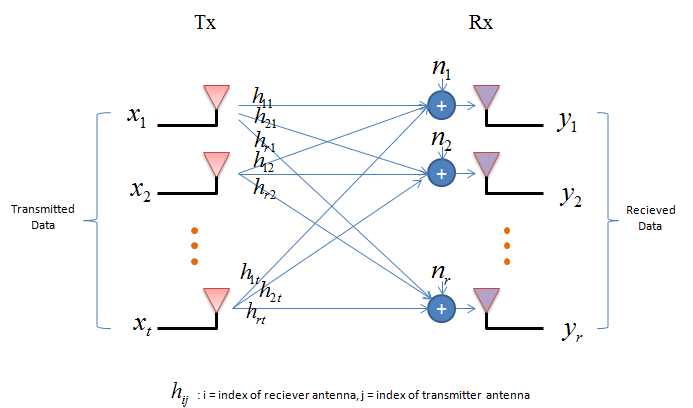
Let's look into following illustration. It has many transmission antenna (labeled as Tx) and many reciever antenna (labeled as Rx). Number of Tx antenna is labelled as 't' and the number of Rx antenna is labelled as 'r'. For example, if t = 2 and r = 2, it becomes 2 x 2 MIMO configuration.
And you see all the possible correlations between Tx antenna and Rx antenna and each of those correlations are labeled as 'h'. The subscript of 'h' is represented in the form of 'h_rx_tx'. For example, h21 means the channel coefficient between 'tx antenna 1' and 'rx antenna 2'.
'n' represents a noise added to each of the reciever antenna. In really, there are many different sources of noise coming into each antenna, but in the mathematical model all the noise sources are combined to a single source with a certain statistical distribution. For example, n1 is the combination of all the noise sources coming into Rx antenna 1.
'x' represents each symbol (one spot on constellation) being transmitted by each Tx antenna. For example, 'x1' represents the symbol being transmitted by Tx antenna 1.
'y' represents signal (one spot on constellation) being recieved by each Rx antenna. For example, 'y1' represents the signal being recieved by Rx antenna 1.
If you just directly translate the illustration above into a mathematical expression you will get multiple equations as follows. This kind of conversion goes on almost automatically in the brain for the engineers who is working in this area or any kind fo system modeling, but don't get frustrated if you are new to this. Just take only one antenna (y1 for example) and try to mapping each term (e.g, h11 x1, h12 x2) to the illustration and you will understand how each of these equations came out.

Then if you just convert this simultaneous equation (system equation) into a vector/matrix form, you would get following equation.
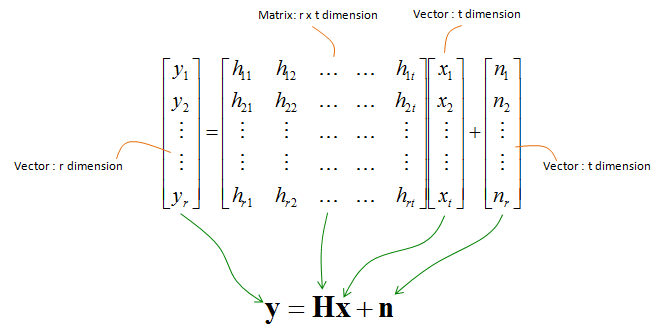
This simple equation (y = Hx + n) is the starting point of almost any channel modeling and channel estimation. Once you get this system equation, you need to go through a long, tedious, boring, confusing process to derive various other information as illustrated below.

Do you know what is the most difficult part with studying this subject ?
You may have different answer to this question. At least to me, the answer is "It is so boring and dry". So to keep focusing in the subject without falling into sleep for more than 20 minutes was the most difficult part for me :). You might have similar problem when you were sitting in Linear Algebra course in the university. You will experience the same thing even while reading down from next section. But once you get more and more familiar with this subject and all of those mathmatical formula start looking like your verbal language, then you would feel like reading a novel when you read through the material about this subject. To be honest, I am not there yet... I can just stay up a little bit longer than 20 mins without falling a sleep :)

From the Generalized Mode, we can derive roughly three different typical cases as shown below. The details of each of the cases will be explained in separate pages linked below.
|
|
|
|
|
Tx > 1, Rx > 1 |
Tx = 1, Rx > 1 |
Tx > 1, Rx = 1 |
NOTE : If you are new to the mathematical process of channel modeling, I recommend you to study Rx Diversity case first and understand the mathemical meaning of each and every line in the page and then proceed to other cases.
YouTube
[1] Lecture 11: Principle of Diversity
[2] Lecture 12: Multiple Antenna Diversity
[3] Lecture 13: Maximal-Ratio Combining
[4] Lecture 34: Multiple Input Multiple Output (MIMO) Systems
[5] Lecture 35: Examples of MIMO Systems
[6] Lecture 36: MIMO Receivers
[7] Lecture 39: Alamouti Code and Space-Time Block Codes