|
Communication Technology |
|||||||||||||||||||||||||||||||||||||||||||||||||||||||||||||||||||||||||||||||||||||||||||||||||||||||||||||||||||||||||||||||
|
Why we need Digital Encoding ?
First I assume that you know what Encoding is (Refer to Encoding page if you are not familiar with the concept of Encoding). Now the question is why we need Digital Encoding. Here goes some of the reason why.
< Spectral Efficiency >
According to Fourier Transform, a Digital Pulse contains frequencies of infinite range. So theoretically we need to implement a physical medium that can transfer the signal with infinite frequency range, but it is practically impossible. So it would be good if we can have a some technique to concentrate the frequency of digital signal into a specific region as narrow as possible. Channel Coding can be a measure to achieve this goal.
< Removing DC Offset >
If we just map the digital bit 1 to +V volt and bit 0 to +0 volt (or -V volt), a certain bit pattern (all zero bit or all one bit) can create DC Offset along the communication media which may cause various problem. By applying a proper Digital Encoding technique, you can reduce (even though you may not completely remove) the DC offset.
< Assisting Synchronization >
A certain signal pattern which does not have much transition in it (e.g, long period of '+V' or long period of '-V') may make it difficult for the reciever to get synchronized. By applying a proper encoding technique, you can reduce such a period in which the signal stays at the same voltage level. It helps synchronization on reciever side.
< Increase immunitity against Signal Interference and Noise >
Some Coding Technique can shows the better performance in terms of BER vs SNR.
Followings are some of the digital encoding techniquest commonly used in the field. You would often come across these words when you are reading specification sheet or technical documents about digital communication system.
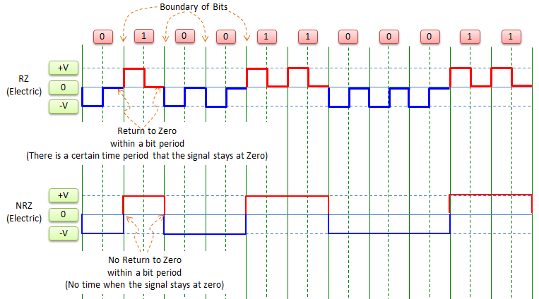
RZ stands for 'Return to Zero' and NRZ stands for 'No Return to Zero'. As shown in the following illustration, in RZ there is a certain period in which the signal level goes to 'zero' and stays there for some time. In NRZ, the signal jump between +V and -V at the bit boundary and never stays at zero within the bit duration.
There a couple of different type of NRZ. In concept, you can map the bit to +V or to -V in any way. The illustration shown below shows the case where '1' maps to '+V' and '0' maps to '-V'.
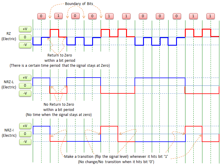
In practice, special type of NRZ valled 'NRZ-L' and 'NRZ-I' are more frequency used. In NRZ-L, the bit '0' maps to electric level '+V' and the bit '1' maps to the electric level '-V' as shown below. In NRZ-I, the bit value does not map to any specific signal level, the bits are mapped to a certain transistion of signal level. '1' maps to 'transition' and '0' maps to 'no transision'. When it hits '0, the signal level stay same as the signal level of previous bit whatever it is. When it hits '1', the signal level changes to opposite value from the signal level of previous bit. (It may be a little bit confusing at the beginning, so try to understand the concept clearly)
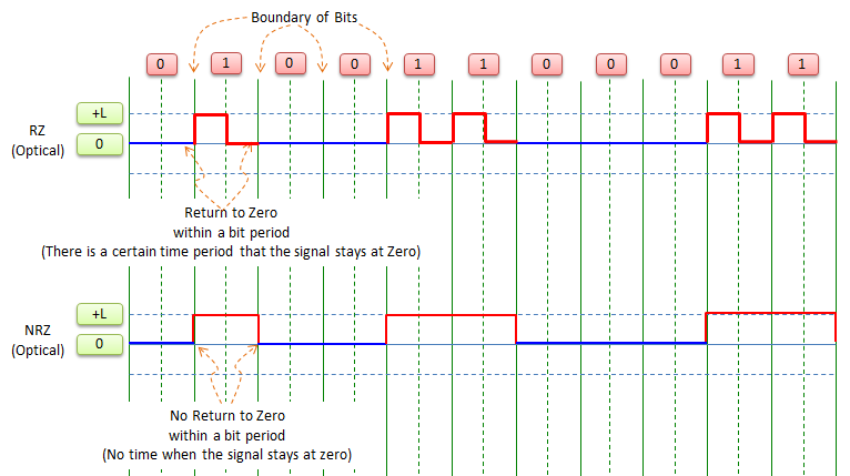
In case of electrical signal, we can map plus(+) and minus (-) level signal to the bit '1' or '0', but in case of optical signal, we cannot do the same thing since there is no minus (-) level in optics. so one of the optical bits should be mapped to zero as shown below.
< Pros and Cons of NRZ >
Pros :
Cons :
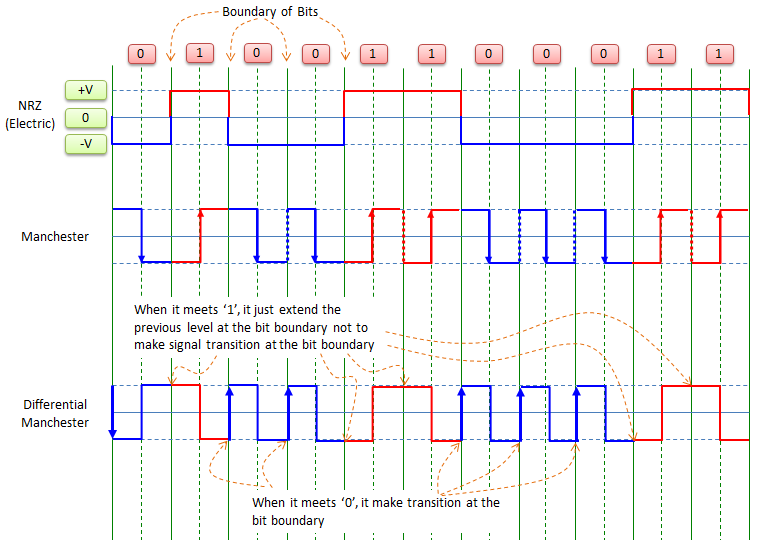
Manchester / Differential Manchester
In Manchester and Differential Manchester, both 0 and 1 is mapped to a certain pattern of transition. So whatever the bit pattern, you would always see the transition. The transition pattern is defined as follows :
Manchester :
Differential Manchester :
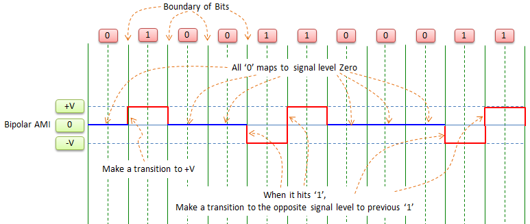
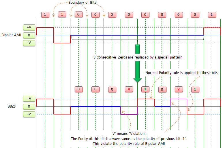
Bipolar AMI (Alternative Mark Inversion)
This encoding method is using 3 signal levels (+V, 0, -V). and mapping goes as follows :
Pros :
Cons :
3B/4B Encoding is a method to replace '3 bit' original data (input) with '4 bit' data (output). The input and output mapping of this encoding is based on following table. (Auctually this table just shows the result of the encoding, but in many case real implementation is done by statemachine running a predefined rule).
5B/6B Encoding is a method to replace '5 bit' original data (input) with '6 bit' data (output). The input and output mapping of this encoding is based on following table. (Auctually this table just shows the result of the encoding, but in many case real implementation is done by statemachine running a predefined rule).
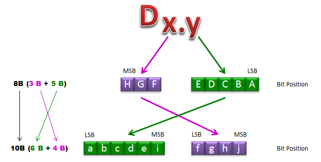
8B/10B Encoding is a method to replace '8 bit' original data (input) with '10 bit' data (output). This encoding is implemented by combining two simpler encoding method 3B/4B and 5B/6B as illustrated below.
Describing this in written form, it goes as follows. i) Take the Input Data Bits: HGFEDCBA ii) Split the Data into two blocks: HGF EDCBA iii) Swap the position of the two blocks/shuffle the bits in each block : abcdei fghj
8B/10B is a kind of encoding scheme and it is not the predefined encoding table. The output of 8B/10B would vary depending on how the shuffling statemachine is defined. So you would need to refer to the specification of each application if you want to know exact mapping table for any specific application.
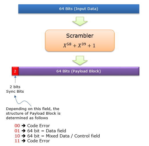
64B/66B encoding convert a 64 bit input block into 66 output block using a complicated scrambling algorithm (not a fixed mapping table). The structure of the output block varies in many different structure and the type of the structure is indicated by the two sync bits at the beginning of the output block as shown below. This econding method is mainly used for 10 Gbit Ethernet (if you are interested in further details, refer to the documents in Reference section).
References :
[1] 8B/10B Coding,64B/66B Coding [3] Introduction to 10 Gigabit 64b/66b (Clause 49) [4] 10G ETHERNET 64B/66B ENCODING
|
|||||||||||||||||||||||||||||||||||||||||||||||||||||||||||||||||||||||||||||||||||||||||||||||||||||||||||||||||||||||||||||||