|
Electronics |
||
|
ADC (Analog to Digital Converter)
ADC stands for Analog to Digital Converter. As the name suggest, it is a device that convert Analog signal to Digital Data. I would say ADC is one of the most crucial component in most of electronic application. Especially in digital wireless communication, it is impossible to make it work without ADC because in wireless system the data should go through a analog medium (e.g, Air between the transmiter and reciever) and the data should be processed in digital format in device baseband.
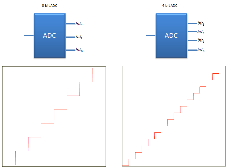
In simple block diagram, it can be represented as follows.
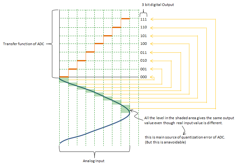
If I represent the function of ADC in more formal way, it can be represented as follows. (This is ideal behaviour of ADC with 3 bit output as an example).
Number of Output Bits and Resolution
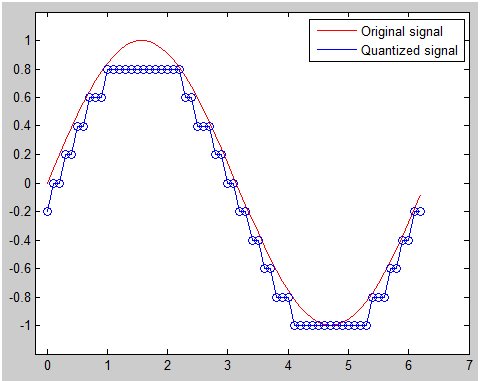
If I plot the example of 3 bit ADC with a sinosoidal input and its output on a same graphic plane, it can be represented as follows. The red line represents the input analog signal and the points on blue line represents the output data. In ADC, the blue point is output as a bit data (like 000,001,010 etc) and each of these bit sequence is translated into corresponding signal level at later steps. As you see here, many different values on input signal (red line) can be converted to the same output value.
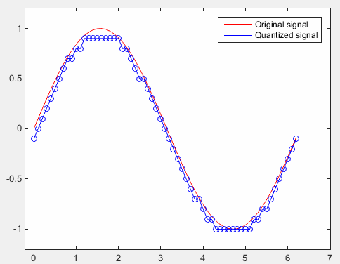
Let's look at the following plot. You see the output value is finer (more granullar) comparing to the plot shown above. You can have this kind of finer output if you use an ADC with more output bits.
Bit Resolution, Quantization Error, ENOB, SNR, SINAD
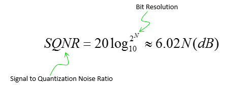
Explicit meaning of the bit resolution is just the number of output bits for ADC and practical meaning of Bit resolution is how closely the digital output can represent the analog input. Generally the higher the bit resolution is, the better (the more closely) the digital output represent the analog input signal. As explained above, by the nature of ADC, the device can never duplciated the input signal 100% accurately. There is always a certain difference between each digitized value (output) and the original analog value(input), this difference is called Quantization error. Due to this quantization error, there is a certain limitation in terms of SNR. Putting aside the SNR degradation due to thermal error, the SNR contributed by the bit resolution can be expressed as follows. Just putting it in practical terms, we can say SNR gets better as bit resolution gets higher. Putting it more quantitatively, you can say you can get around 6 dB better SNR as you get 1 bit higher bit resolution.
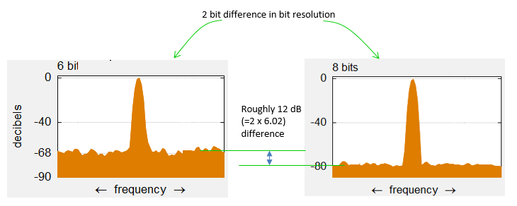
This rule can be illustrated in an example as follows. (The original plot came from Wikipedia : Analog-to-digital converter and I edited the original plot so that it can show this property more clearly).
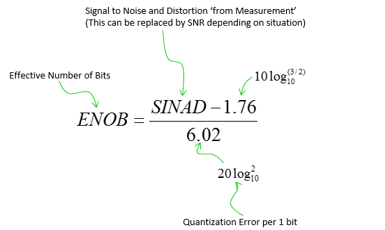
As I always says, life would not go as textbook says. In most case, the real life goes worse than the expectation. Same applies to SNR rule based on bit resolution as well. For example, let's suppose that we have 16 bit ADC. According to the rules shown above, the SNR based on bit resolution (quantization error) should be 96.3 dB (6.02 x 16). However, if you measure the SNR (or SINAD) of the real device, you will get a little bit (or much) lower SNR than the expected value. It means you will get the SNR as if you are using an ADC with lower bit resolution than the specification sheet says. To evaluate this SNR degradation in real device, they are using an indicator called ENOB (Effective Number Of Bits). The basic concept is to reverse engineer the resolution bits based on the measured SNR (SINAD) as described below (Refer to Reference [1] for the details). If you calculate ENOB this way, it will be lower than the ideal bit resolution. The difference between ENOB and the ideal bit resolution may be an indicator showing the degree of SNR degradation of the device.
The SNR (SINAD) that I mentioned above is based on the assumption that the amplitue input signal is the maximun amplitude for the device (fullscale amplitude), but we don't always input the full scale signal. If the input signal is smaller than full scale, the measured SINAD (SNR) would be lower than the best possible value. This is because the peak value in frequency domain will get lower than the max value, but the noise floor does not always gets lower as much as peak value gets lower. So we need to revise the ENOB calculation equation a little bit when we use the input amplitude that is lower than the full scale amplitude. That revision is as follows (Reference [1])
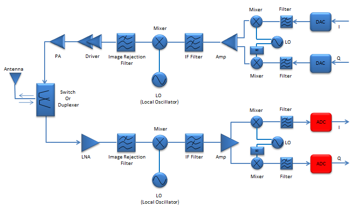
One of the most common application of ADC is for wireless communication as illustrated below.
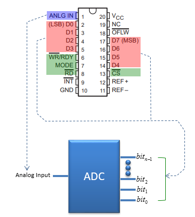
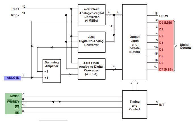
Example 01 : TLC0820AC, TLC0820AI (Texas Instruments)
Reference
[1] Understand SINAD, ENOB, SNR, THD, THD + N, and SFDR so You Don't Get Lost in the Noise Floor by Walt Kester [2] A Glossary of Analog-to-Digital Specifications and Performance Characteristics [3] Understanding analog to digital converter specifications [4] Understanding ADC Parameters [5] Testing ADCs in embedded systems with Rohde & Schwarz oscilloscopes [6] The ABCs of ADCs: Understanding How ADC Errors Affect System Performance [7] ANALOG-DIGITAL CONVERSION (Testing Data Converter) [8] SNR to Resolution converter
|
||

