|
Embedded System |
||
|
CAN
CAN stands for Control Area Network. Many people call it as 'CAN BUS'. It is originally developed by BOSCH.
Just from these three statements you may get pretty good insight without reading anything further. From the word 'Network' or 'BUS', you would guess overall architecture of CAN. It implies that CAN is a kind of common communication channel that can connect multiple devices simultaneously. From the fact that it is first developed by BOSCH, you may easily guess that the major application of CAN would be Automotives.
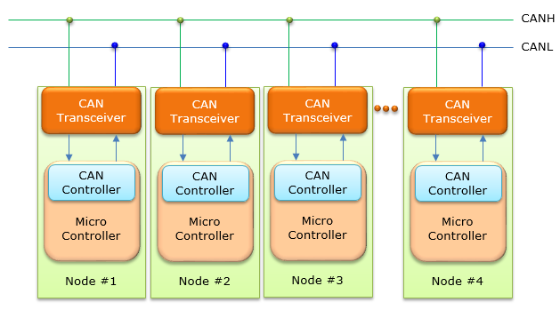
Overall CAN architecture looks as follows. As you see here a lot of devices (Nodes) shares a common communication lines (BUS) and it forms a kind of network. Like I2C, the common data line is made up of only two lines (Of course, in real CAN system you will see many more lines since it need power line, ground line etc. This is also same as in I2C). Unlike I2C, both lines of the bus is for data (it is for the same data represented by two different signal level) whereas in I2C only one line is for data and the other line is for clock signal). You may notice another difference from I2C from this picture. There is no Master and no Slave in CAN. It means every Node can transmit the data at the same time. I know what you think now.. what if multiple nodes transmit the data exactly at the same time and those signal colide each other ? Good Question. There should be some mechanism that can prevent this kind of collision happening. You would learn about this later.
Basic Features
Follwoings are the list of basic features of CAN (To me, the most important characteristics comparing to other types of communication method is that it provides very robust Error checking method, meaning high reliability. Also comparing to I2C, SPI, Serial, it can cover very long distance)
Frame Structure
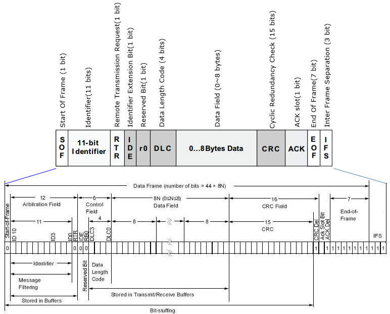
Frame Structure of CAN is as follows. One thing that I noticed was there is no 'address' field. What does this mean ? It implies that in CAN the transmitted frame is no specific target. It is for every node(device) connected to the network (BUS). In other words, CAN is basically for broadcasting data. Every device in the network recieves the same data and it is up to the reciever whether use the data or just discard it.
Why CAN ?
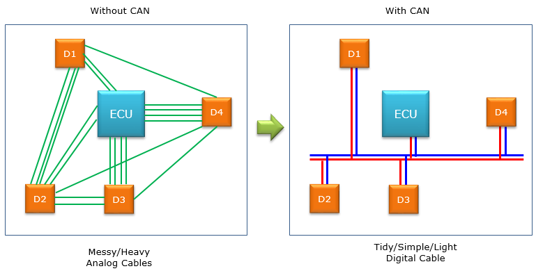
The biggest motivation for CAN is to remove all those spaghetti-like (messy) and bulky wires connecting multiple devices within a car. Simply put, it can be illustrated as below.
See reference [5], [6] and they will give you more realistic reasons on why CAN ?
Reference :
[1] Controller Area Network Physical Layer Requirements (Texas Instrument - Application Report) [2] Controller Area Network (CAN) Tutorial (National Instrument) [3] CAN Specification (v2.0)- Embedded System Design [5] WHY ALL THE FUSS ABOUT CAN BUS? [6] Why is there a bus in your car? And why does HERE care? [7] CAN data link layers in some detail [8] Understanding CAN with Flexible Data-Rate (CAN FD)
|
||


