This page explains how GSM divides the time on one carrier. The smallest unit is a slot of about 577 microseconds, and the largest is a hyperframe of about 3.5 hours. The page starts with the overall hierarchy. It then shows the five burst types that fill one slot, and it ends with how traffic and control channels share the slots of a multiframe. The numbers are checked against 45.001, 45.002 and 45.003 v19.0.0.
The topics on this page are listed below.
- Overall Frame Structure
- Useful Video Links
- Structure of Each types of Burst
- Structure of Multi-Frame
- Slot Allocation in Communication
- Reference
Overall Frame Structure
When I am first trying to study GSM, I got so confused about the overal frame structure. One of the main reason for this confusion is that even a single cycle of a whole structure requires so many slots and frames, it is really hard to visualize the whole frame structure on a limited space of a sheet of paper or on a white board.
I don't find any way to visualize the whole Hyper Frame structure showing the details at the level of every single slots, but overal GSM frame hierarchy is as follows. You would have seen this kind of diagram from various sources.
You have to understand at least the structure of slot, frame, multiframe structure in very detail.
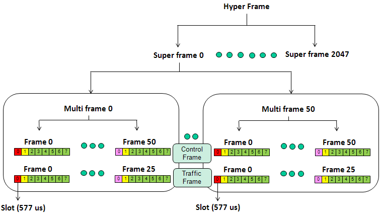
The diagram above reads from the top down. A Hyper Frame holds Super frame 0 to Super frame 2047. Each super frame holds multiframes, and each multiframe holds TDMA frames of eight slots. Inside each multiframe box, the upper row is a control multiframe with Frame 0 to Frame 50. The lower row is a traffic multiframe with Frame 0 to Frame 25.
A slot lasts 576.9 microseconds : this is 15/26 ms, or 156.25 bit periods at 270.833 kbit/s. The diagram rounds it to 577 microseconds.A TDMA frame lasts 60/13 ms : that is about 4.62 ms, and the frame holds the eight slots numbered 0 to 7.The 26-multiframe lasts 120 ms : it carries TCH, SACCH/T and FACCH. This is the Traffic Frame row in the diagram.The 51-multiframe lasts about 235.4 ms : it carries FCCH, SCH, BCCH, CCCH, SDCCH and SACCH/C. This is the Control Frame row. GPRS adds a third type, the 52-multiframe of 240 ms.A superframe is 26 x 51 TDMA frames : it lasts 6.12 s. It holds 51 traffic multiframes or 26 control multiframes, so the label Multi frame 50 fits the traffic multiframes only.A hyperframe holds 2048 superframes : it lasts 3 h 28 min 53.76 s, and the TDMA frame number FN runs from 0 to 2715647.
Let's check why the superframe has exactly this length. A superframe holds 26 x 51 = 1326 TDMA frames, and 1326 x 60/13 ms = 6120 ms. So 51 traffic multiframes and 26 control multiframes both end at the same moment, and the two structures restart together every 6.12 s.
The hyperframe is much longer for a different reason. Ciphering uses FN as an input, so FN must not repeat within a short time. The MS learns FN from the SCH, which the Synchronization Burst below carries. The SCH sends T1 = FN div (26 x 51), which is the superframe number, and T2 = FN mod 26. It also sends T3' = (T3 - 1) div 10, where T3 = FN mod 51. From these values and the position of the SCH in the 51-multiframe, the MS rebuilds the full FN.
Every level is a whole number of the level below : 8 slots make a frame, 26 or 51 frames make a multiframe, 1326 frames make a superframe, and 2048 superframes make a hyperframe.The superframe aligns the two multiframes : its 1326 frames are the least common multiple of 26 and 51.FN numbers every frame of the hyperframe : the MS reads it from the SCH, and ciphering depends on it.
Useful Video Links
Followings are a couple of video tutorial that I found from YouTube which would greatly help you understand overall GSM frame and channel structure. I strongly recommend you to go through these tutorials at least once and then this page can be a good cheat sheet to remind your memory and solidify your understanding.
Structure of Each types of Burst
In almost every wireless communication, we use various kind of channel types. Each of those different channel tend to have its own physical (or transport layer) structure. In GSM as well, we have many different types of physical and logical channels and each of these channel types are using its own physical structure at the level of a slot (Burst). Followings are the types of Burst being used in GSM/GPRS.
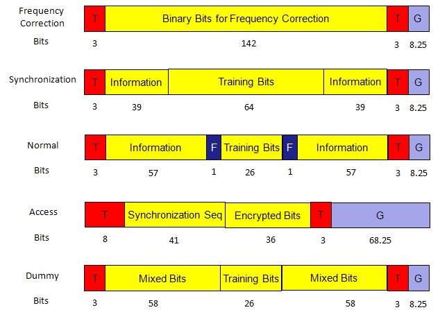
Every GSM/GPRS physical channels are mapped to one of these burst types and the mapping is described below. Each of the physical channel is also mapped to higher layer channel types called Logical channels. These mappings are summarized in a table in Quick Reference page.
The diagram above draws the five bursts on the same slot. Every burst except the access burst starts and ends with 3 tail bits, marked T, and leaves a guard period of 8.25 bits, marked G. The access burst starts with 8 extended tail bits and leaves a guard period of 68.25 bits. The parts of each row add up to 156.25 bits, which is exactly one slot.
Frequency Correction Burst
The frequency correction burst carries no information, only a fixed pattern. The MS searches for this pattern to find the BCCH carrier and to correct its own frequency error. In the 51-multiframe, the FCCH appears in timeslot 0 of frames 0, 10, 20, 30 and 40.
- This burst format is used by FCCH channel only.
- The whole data space (142 bits) is used for unmodulated carrier (pure sinusoid) or carrier modulated with all zero bits.
- The frequency is 1625/24 kHz (or approximately 67 kHz).
- This pure carrier is the ‘identity’ of a beacon frequency (also called BCCH-frequency or base-frequency) and FCCH slot.
Synchronization Burst
The synchronization burst always comes one frame after an FCCH burst, in frames 1, 11, 21, 31 and 41. So once the MS has found the FCCH, it knows where to look for the SCH. The SCH gives the MS the BSIC and the frame number, and the MS needs both before it can read the BCCH.
- This burst format is used by SCH channel only.
- This channel makes a mobile station time-synchronized with the base station clock. That is why the synchronization training sequence is very large for this burst comparing to other burst types.
- Only one training sequence is defined for this burst.
Access Burst
The access burst is the only burst that an MS sends before it knows its timing advance. For this reason, it is short and it ends with a long empty guard period. The MS sends it on the RACH, and also on the uplink of the new channel during handover.
- This burst format is used by RACH channel. AGCH is a downlink channel and uses the normal burst.
When a mobile station sends an RACH message and receives an AGCH reply, neither MS nor the BTS does have the timing-advance information. For that reason, the actual message is relatively short and have a long guard band (GB) in order to make sure that there will be no overlap with the next burst. The length of the guard band in the access burst (68.25 bits x 3.69 microseconds = about 252 microseconds) is equivalent to 37.5 km propagation delay. The GSM allows a cell radius up to of 35 km. That is, an RACH message from an MS at a distance of up to 35 km from the base station can reach to the base station antenna without overlapping the next burst. The FACCH channel uses this burst during handover operation (when the timing advance of new cell is not yet known). Only one training sequence is defined for this burst.
The 36 encrypted bits carry the channel request. For the basic RACH, 45.003 takes 8 information bits and adds 6 parity bits. It then adds the BSIC of the target cell to the parity bits bitwise, so only the intended cell decodes the request. With 4 tail bits, the rate 1/2 code produces the 36 bits.
Normal Burst
The normal burst carries almost everything else, both traffic and signalling. Its 26 bit training sequence sits in the middle of the burst, so the channel estimate is close in time to both halves of the data. The training sequence is one of eight codes, the TSC, and for BCCH and CCCH the TSC equals the BCC of the cell.
- This burst format is used by all other channels (except FCCH, SCH and RACH).
- This normal burst is used by TCH, SDCCH, SACCH, FACCH, BCCH, PCH and AGCH.
A few important features of the burst is stated below.
o Maximum 57 x 2 = 114 bits of voice/data per burst
o Flag bit is to indicate if the channel is carrying user traffic (Flag = 0) or control message bits (Flag = 1).
That is the flag is 0 for TCH and 1 for others.
45.002 now counts the two flag bits as part of the encrypted bits. So the current table shows 58 + 26 + 58 instead of 57 + 1 + 26 + 1 + 57, and it calls BN60 and BN87 the stealing flags. The layout on the air is the same. When FACCH steals a TCH block, the flags mark which half of the burst carries signalling.
Dummy Burst
The dummy burst fills a gap. The BTS must transmit a burst in every timeslot of every TDMA frame on the BCCH carrier C0, because MSs measure the power of this carrier. When no channel uses a slot on C0, the BTS sends a dummy burst there.
This is like normal burst but has no meaning of its payload bits.
Every burst fits 156.25 bit periods : the parts of each row in the diagram above add up to one slot, guard period included.Only the access burst has a long guard period : the MS sends it before it has a timing advance, so 68.25 bits of silence absorb the round trip delay.AGCH uses the normal burst : the access grant is a downlink message, and the BTS always knows its own timing.FB and SB come as a pair : the FCCH frame is always followed by the SCH frame on timeslot 0 of C0.C0 never goes silent : the dummy burst keeps the BCCH carrier at a constant level, so neighbour cell measurements stay valid.
Structure of Multi-Frame
There are two different kind of Multi-Frames in GSM. One is called 'Control Multiframe' and the other one is called 'Traffic Multi Frame'. (Do you remember where the multiframe is located in overall GSM frame structure ? Let's refresh our memory. Slot --> Frame --> MultiFrame (Control Multiframe, Traffic MultiFrame) --> Super Frame --> HyperFrame. Do this questions and answer by yourself whenever you have chance until your brain automatically pops up a frame structure diagram as soon as you see some key words related to GSM frame).
Following is one example showing a control multiframe. As I said, even a single multi frame has 51 x 8 slots, so it is very hard to visualize the full details on a page. You will see a better way to visualize this structure at later section, for now just try to get some 'sense(feeling)' of how a multiframe looks like. One thing worth noticing would be the first slot in each frame seems to be used as some control channel. In this diagram, the second slot in each frame is being used as a control channel but it is not always the case.
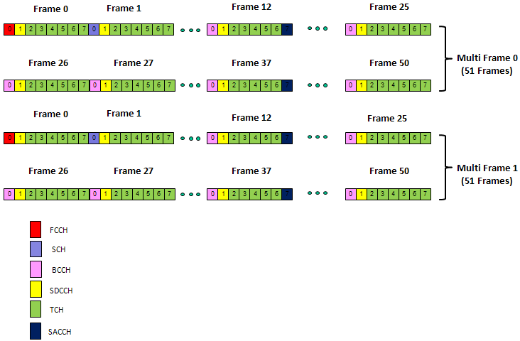
The diagram above is a sketch, not an exact channel map. Slot 0 carries FCCH, SCH and BCCH, slot 1 carries SDCCH, and slots 2 to 7 carry TCH. A SACCH block sits in slot 7 of frames 12 and 37. The legend at the bottom gives the colour of each channel.
Keep two points in mind when you read it. First, a TCH slot follows the 26-multiframe, not the 51-multiframe. In a real cell, frames 12 and 25 of each 26 frames carry the SACCH or are idle, as the Slot Allocation section below shows. Second, slot 0 carries FCCH and SCH only in frames 0 and 1, 10 and 11, 20 and 21, 30 and 31, and 40 and 41. BCCH takes frames 2 to 5, and most of the other frames carry CCCH, not BCCH.
Each multiframe type has its own channels : the 26-multiframe carries TCH, SACCH/T and FACCH. The 51-multiframe carries FCCH, SCH, BCCH, CCCH, SDCCH and SACCH/C.The structure belongs to the timeslot : one timeslot runs either the 26 or the 51 structure, and its neighbour on the same carrier can run the other one.The idle frame lets the MS look at neighbours : 26 and 51 have no common factor. So the idle frame of a traffic multiframe falls on a different frame of a neighbour's 51-multiframe each time. 45.008 uses these idle frames for decoding the BSIC of neighbour cells.
Slot Allocation in Communication
As I keep telling you, the overall GSM frame structure (one cycle) is so long in time domain and I haven't see any material showing even a single multiframe at the full details of each slot.
I googled a lot and went through a lot of different material and then I came across a document named "GSM Phy Part-1.pdf" and with just a glimpse of a couple of diagram there, I exclaimed myself "This is it !!!!!!". All of sudden a clear pattern within a multiframe start showing up.
Followings are those couple of diagrams from GSM Phy Part-1.pdf and I redraw the diagram just for my practice. Don't just look at these diagrams if you are GSM beginner, draw grids on a paper or open up a Excel spreadsheet and color and label it on your own. Sometimes you would notice what we did in the kindergarden still works very well when you are at the age when you have your own kindergarden kids -:).
Most of the examples in this section is regenerated based on GSM Phy Part-1.pdf created by Monzur Kabir, Ph.D., P.Eng. (Another good tutorial I want to recommend is How 26 and 51 Multiframes in GSM).
Following illustration shows the time domain structure in slot level. As you see, the minimum unit is a slot and 8 slots (slot 0 to 7) makes one step bigger unit called a frame.
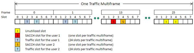
One label in the diagram above does not match the rest of the page. It shows the SACCH slots in frame 13, but frames are numbered from 0, and the SACCH of a TCH/F sits in frame 12 of the 26-multiframe. The two dimensional diagrams below place it in frame 12, which matches 45.002.
The above illstration is the closest to real physical signal flow, but it would be a little bit difficult to illustrate on various scheduling issues since the basic scheduling is based in the unit of frames (not in the unit of slots). So people tend to illustrate GSM signal structure in 2 Dimension as shown below. Following is the most basic scheduling for fundamental channels.
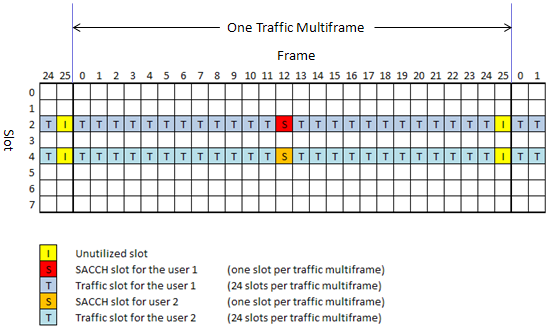
Following is the common example of a Traffic Multiframe. This illustration shows 26-multiframe structure for TCH/FR and TCH/EFR. This example shows 2 users using full rate voice traffic channels. (One user uses the slot 2 at every frame and the other user use the slot 4 at every frame).
At the center of the 26-frame traffic channel multiframe (i.e, Frame 12) is the Slow Associated Control Channel (SACCH) which carries link control information to and from the MS–BTS. At the last frame is 1 idle frame. All the remaining frame are allocated for Traffic. There is no dedicated FACCH frame or slots. FACCH steals TCH whenever it needs.
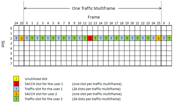
Following illustration shows 26-multiframe structure for TCH/HR, showing 2 users using HR voice traffic channel. In this example, the two users shares the slot 2 of every frame in alternating fashion. You would notice that there are two Frames for SACCH. The Frame 12 is for SACCH of user 1 and Frame 25 is for SACCH of user 2.
The multi frame strcuture for control channel has more complicated and the structure varies depending on the type of the control channels. However, one common thing about all control channel frame structure is that it is based on 51 multiframe.
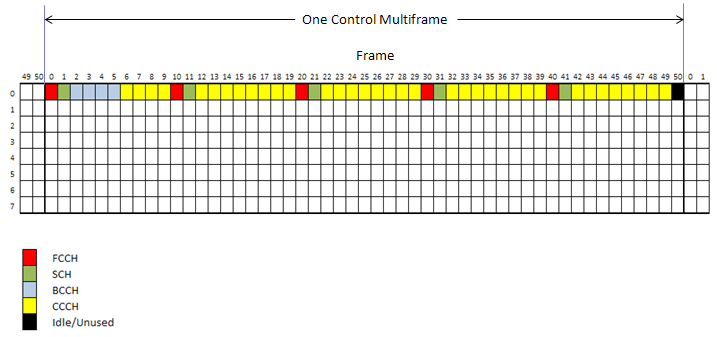
Following is an example of control channel multiframe structure for Beacon Channel (Base Control Channel) which is made up of FCCH, SCH, BCCH, CCCH. The illustration below is for Downlink multiframe structure. In Uplink base control channel case, every frame is for single channel - RACH. Some key facts about DL Base Control Channel are
- There are five FCCH equally spaced within the 51 multiframe.
- Each FCCH is followed by a SCH, meaning that there are five SCH as well.
- Four frames (Frame 2~5) are allocated for BCCH.
- The last frame (Frame 50) is allocated for Idle.
- All the remaining Frames are allocated for CCCH(e.g, PCH or AGCH).
Examples shown above was a kind of simplified illustration for isolated channels (e.g, Traffic and control channels were explained separately.) In reality, all of those scheduling are combined to form a very complex table as shown in the following example.
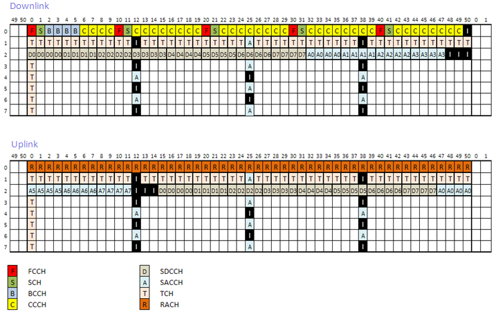
Let's read the combined map above row by row. In the downlink, slot 0 carries the FCCH, SCH, BCCH and CCCH pattern of the control multiframe, and in the uplink every frame of slot 0 is RACH. Slot 1 and slots 3 to 7 are TCH, with SACCH or idle in frames 12, 25 and 38. Slot 2 carries SDCCH/8, marked D0 to D7, with its SACCH marked A0 to A7. In the uplink, D0 starts 15 frames after the downlink D0, which gives the MS time to answer on the same subchannel.
TCH/F uses 24 of 26 frames for traffic : frame 12 carries the SACCH, and frame 25 is idle.TCH/H splits one slot between two users : each user gets every other frame, and the SACCH of the second user moves into frame 25.Timeslot 0 of C0 is the beacon : it carries FCCH, SCH, BCCH and CCCH in the downlink, and RACH in the uplink.The SDCCH/8 uplink is delayed : 45.002 maps the uplink block of each SDCCH/8 subchannel 15 frames after its downlink block.
Following quote from GSM Phy Part-1.pdf would give you pretty good high level picture of these scheduling occuring in real situation.
A GSM base-station (called Base Transceiver Station or BTS) has one or more GSM frequency channels (ARFCN). One of those frequency channels is defined as the base-frequency (beacon frequency or BCCH frequency). The first time-slot (Slot-0) of the base-frequency TDMA is used as the base-control channel (or beacon channel). Remaining part of the frequency channel (Slot-1 to 7) can be used as any mix of traffic and control channels. All other frequencies are mostly for traffic but can also be used for control channels. Mix of traffic and control channels depends on number of frequency channels per BTS (that is the capacity of a cell) and the traffic patterns. Examples:
- Infrequent calls need less RACH channels
- Shorter calls and/or less number of voice calls need less TCH
- High traffic cell has a large number of frequency channels and it is likely that the base-frequency channel will have no traffic channel.
Reference
- 45.001 Physical layer on the radio path; General description - v19.0.0, subclauses 5.1 Hyperframes, superframes and multiframes and 5.2 Time slots and bursts
- 45.002 Multiplexing and multiple access on the radio path - v19.0.0, subclauses 3.3.2.2.1 SCH, 5.2 Bursts and 6.5.1, Tables 1, 3 and 4 mapping of logical channels
- 45.003 Channel coding - v19.0.0, subclauses 3.1.4 Mapping on a burst and 4.6.1 RACH carrying 8 information bits
- 45.008 Radio subsystem link control - v19.0.0, subclause 7.2.2 Identification of surrounding BSS