|
3G/UMTS-TDSCDMA |
||
|
Frame Structure
Descriptions will follow later.. enjoy illustrations and screen capture and try to make some story about it on your own for now.
Frame Structure - Time, OVSF, Frequency Domain
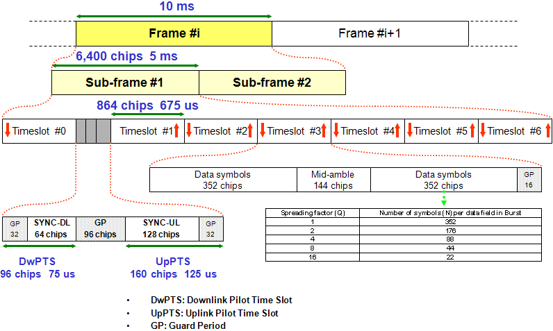
Following is the overall frame structure for 1.28 Mcps options. For other option (e.g, 3.84, 7.68 Mcps), refer to 25.211 5.1 and 5.B1). The details for this section is based on 25.211 5.A1.
Just read following figure and try to verbalize it, you can figure out a lot of details just by "READING" the figure. If I do a little bit of list for you, it would be as follows. (Some items in this list cannot be read from the figure. They are specified in specification)
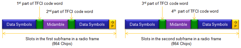
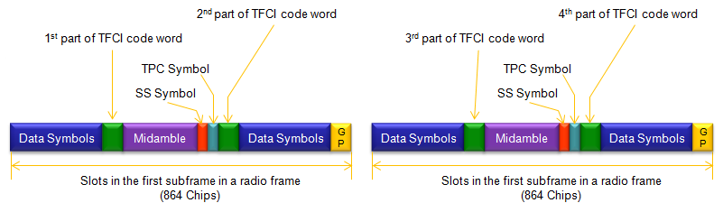
Slot Structure (Burst Format) - 1.28 Mcps
< Dedicated Physical Channel : DPCH >
< Primary common control physical channel : P-CCPCH >
Same as DPCH burst format except that no TFCI is applied.
< Secondary common control physical channel : S-CCPCH >
Same as DPCH burst format and TFCI may apply as well.
< Fast Physical Access CHannel : FPACH >
Same as DPCH burst format
< physical random access channel : PRACH >
Same as DPCH burst format
< High Speed Physical Downlink Shared Channel : HS-PDSCH >
Same as DPCH burst format, but be careful.. slot format for HS-PDSCH is different from PDCH slot format.
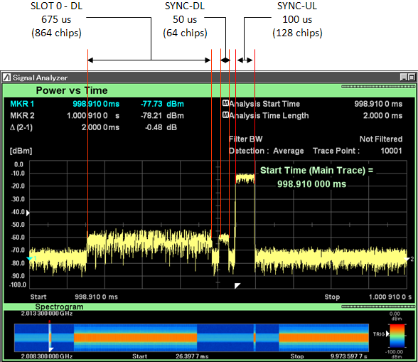
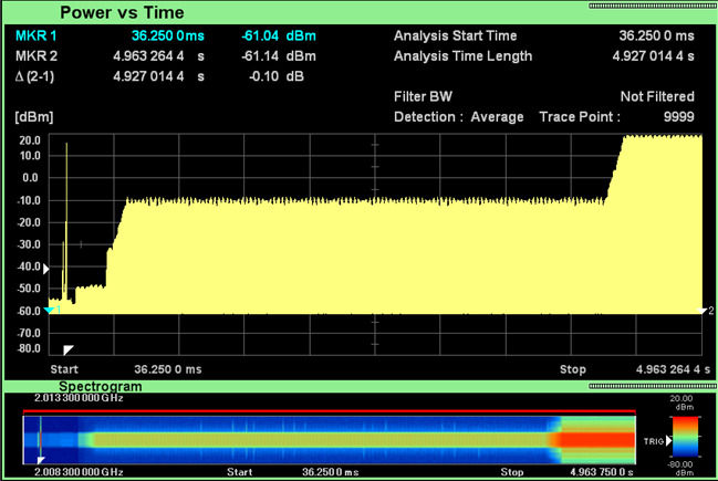
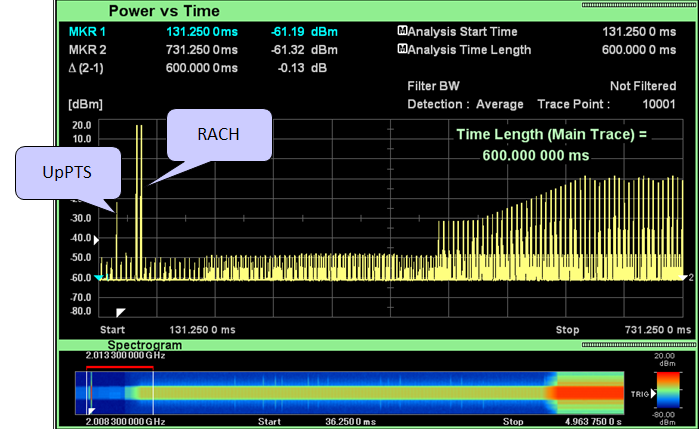
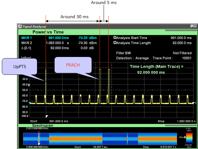
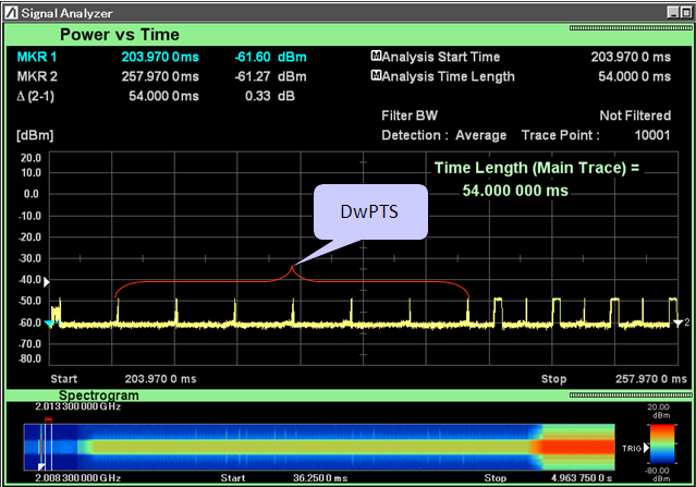
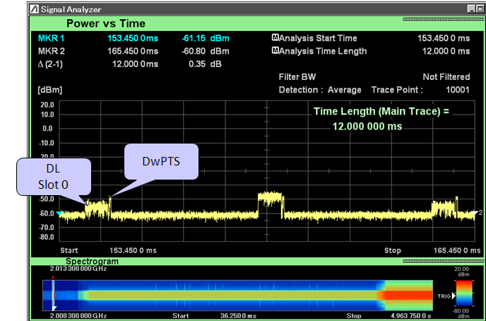
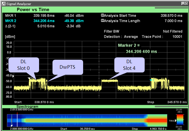
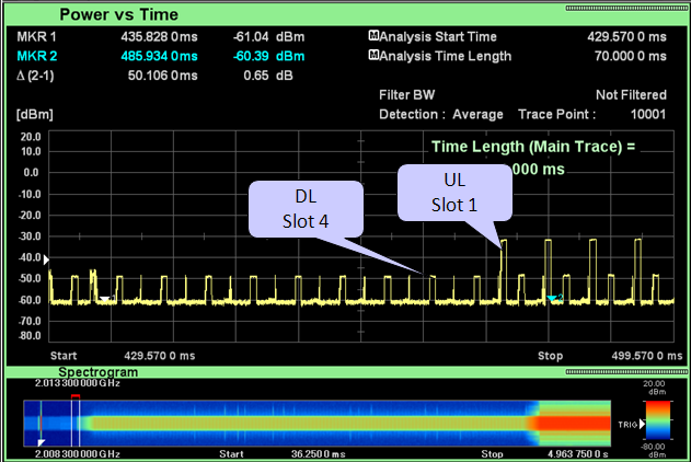
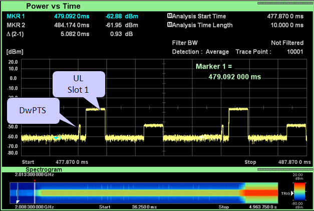
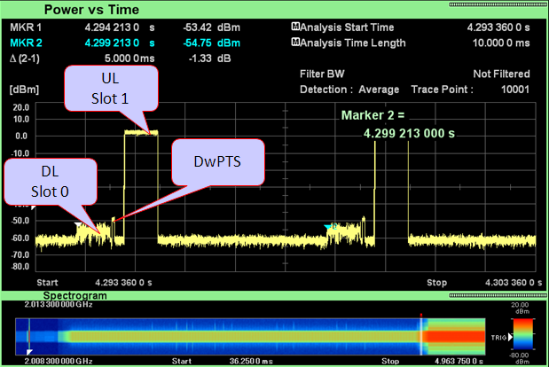
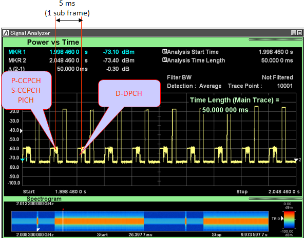
Following is some snapshots of these frame structure being implemented in real application. I captured these subframes during real communication using vector spectrum analyzer.
Frame/Burst in Call Processing
|
||