Descriptions will follow later.. enjoy illustrations and screen capture and try to make some story about it on your own for now. The text added below each set of screens now gives a first reading of them, with the allocations compared against 25.102 Annex A.
An RMC, or reference measurement channel, is a fixed channel configuration that a tester uses to measure a UE under known conditions. Each RMC on this page is shown three ways: as a frame table of slots and codes, as a power versus time trace, and as a code domain display. The pairs ending in 1 are uplink RMCs and the pairs ending in 2 are downlink RMCs. Let's first see how to read the three kinds of screen.
- How do you read the frame table and the analyzer screens ?
- RMC 12.2 K - 1
- RMC 12.2 K - 2
- RMC 144K - 1
- RMC 144K - 2
- RMC 384K - 1
- RMC 384K - 2
- Reference
How do you read the frame table and the analyzer screens ?
The screens on this page use a compact notation, and the same numbers appear in all three views. Once you can move from one view to the other, each RMC can be checked in a few seconds.
The frame table is the same grid as on the Frame Structure page. The columns are Slot 0, DwPTS, GP, UpPTS and Slots 1 to 6 of one 5 ms subframe. The rows CH01 to CH16 are the 16 code positions at SF 16. Each yellow cell holds six numbers in the order given at the top: SF, CH NUM, CH Gain, K, k and Mid Gain.
- SF is the spreading factor, and CH NUM is the code number at that spreading factor, counted from 0.
- CH Gain is the relative power of the code in dB.
- K and k set the midamble. K is the midamble configuration, the number of midamble shifts in the slot, and k is the shift used.
- Mid Gain is the relative power of the midamble in dB.
The power versus time traces cover 11 or 12 ms, a little more than two subframes. The red markers S0 to S6 under the first subframe show the seven traffic slots, so you can see directly which slots carry a burst.
The code domain display shows the power per code position in one slot. A code with a lower spreading factor fills more positions. An SF 8 code fills 2 positions of SF 16, and an SF 2 code fills 8 positions. The display also reports the mean power, the EVM and the channel number with its spreading factor for the marked code.
The table below lists the 1.28 Mcps TDD RMCs that 25.102 Annex A defines, as a baseline for the screens. 25.102 has no 144 kbps or 384 kbps uplink RMC.
RMC |
25.102 table |
Resource units allocated |
UL 12.2 kbps |
Table A.1A |
1 TS, 1 x SF 8 = 2 RU per 5 ms |
DL 12.2 kbps |
Table A.2A |
1 TS, 2 x SF 16 = 2 RU per 5 ms |
DL 144 kbps |
Table A.4A |
2 TS, 8 x SF 16 = 16 RU per 5 ms |
DL 384 kbps |
Table A.5A |
4 TS, 9 x SF 16 = 36 RU per 5 ms |
All four use a 144-chip midamble and 20 ms interleaving. A resource unit counts as 1 for one SF 16 code in one slot, so the SF 8 code of the uplink 12.2 kbps RMC counts as 2.
Six numbers describe one code : SF, code number, gain, K, k and midamble gain.Width in the code domain gives the spreading factor : SF 8 fills 2 positions and SF 2 fills 8.25.102 is the baseline : differences between a screen and Annex A come from the test setup.
RMC 12.2 K - 1
This is the uplink 12.2 kbps RMC, the smallest configuration on the page. It uses one code in one slot, so it is the easiest place to connect the three views.
The frame table below has a single entry, in Slot 1 on CH01: 8,0,0,2,1,0. So the UE sends one SF 8 code, code 0, at 0 dB gain, with K = 2 and k = 1.
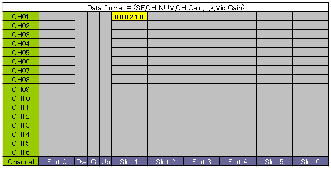
One SF 8 code in Slot 1 is the whole uplink 12.2 kbps RMC.
The trace below shows one burst per subframe at about -20 dBm, in slot S1, and nothing in the other slots.
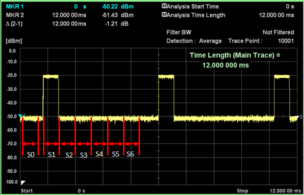
The burst repeats in S1 every 5 ms.
The code domain display below shows the code as channel 1 at SF 8 with 0.00 dB. It fills two positions, as its label says, because one SF 8 code covers two SF 16 codes. The mean power is -20.70 dBm and the EVM is 0.55 % rms.
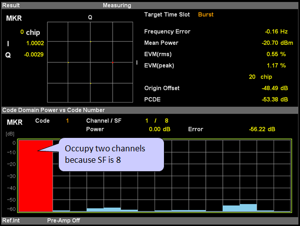
The single SF 8 code fills two SF 16 positions and carries all the power of the slot.
This matches 25.102 Table A.1A exactly: 1 TS with 1 x SF 8, which is 2 RU per 5 ms. The same table gives 16 TFCI bits and 4 TPC bits per user per 10 ms. It also keeps 4 bits in the place of the SS, reserved for future use.
One code, one slot : the uplink 12.2 kbps RMC uses a single SF 8 code in Slot 1.The screens match the specification : the allocation is the one in 25.102 Table A.1A.
RMC 12.2 K - 2
This is the downlink 12.2 kbps RMC. The downlink uses SF 16 only, so the same data rate needs two codes instead of the one SF 8 code of the uplink.
The frame table below has entries in two slots. Slot 4 carries CH01 and CH02 as 16,0,0,8,1,0 and 16,1,0,8,1,0, which are codes 0 and 1 at SF 16 with K = 8. Slot 0 has the same two entries, and the DwPTS column is also marked.
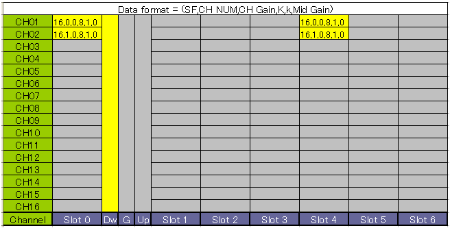
The RMC itself sits in Slot 4, and Slot 0 and the DwPTS are also transmitted.
The Slot 0 entries use the first two codes of time slot 0. 25.221 subclause 5A.3.1 puts the P-CCPCH on exactly these two codes, so these entries are most likely the P-CCPCH that the cell sends next to the RMC. The trace below shows bursts in S0 and S4 of every subframe.
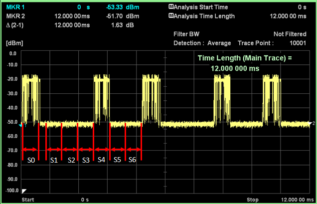
The downlink bursts appear in S0 and S4, about 3 ms apart.
The code domain display below shows two SF 16 codes at -3.01 dB each. Two equal codes that share the power of a slot are each 3 dB below the total.
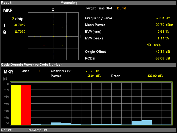
Two SF 16 codes share the slot power equally.
This matches 25.102 Table A.2A: 1 TS with 2 x SF 16, 2 RU per 5 ms. The table also gives 4 TPC bits, 16 TFCI bits and 4 SS bits per user per 10 ms.
Two SF 16 codes replace one SF 8 code : the downlink uses SF 16, so it needs twice the codes for the same rate.Slot 0 is not part of the RMC : its two codes are the P-CCPCH positions of 25.221.
RMC 144K - 1
This is a 144 kbps uplink configuration. It needs far more capacity than one SF 8 code, so it uses a low spreading factor and two slots, which also shows how a UE combines two codes in one slot.
The frame table below has entries in Slot 1 and Slot 2. Each slot has CH01 as 2,0,0,2,1,0 and CH02 as 8,4,-6.03,2,1,-6.03. So each slot carries an SF 2 code at 0 dB and an SF 8 code at -6.03 dB.
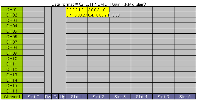
Two uplink slots, each with one SF 2 code and one SF 8 code.
The trace below shows a wide burst across S1 and S2 in every subframe, with a short dip at the slot boundary.
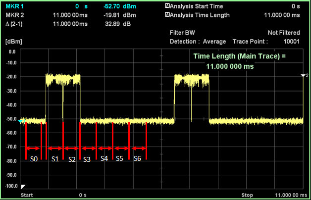
The uplink occupies S1 and S2 back to back.
The two code domain displays below are for TS1 and TS2. In both, the SF 2 code fills 8 positions at -0.97 dB, and the SF 8 code fills 2 positions at about -7 dB. The gains explain these numbers. A gain difference of 6.03 dB is a power ratio of 4 to 1, so the two codes take 80 % and 20 % of the slot power. That is -0.97 dB and -6.99 dB of the total.
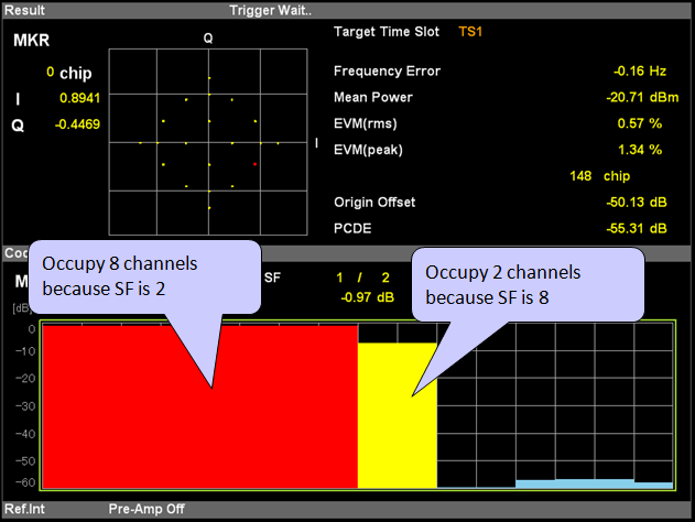
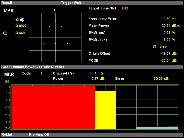
Both uplink slots have the same code layout: the SF 2 code fills 8 positions and the SF 8 code fills 2.
Two codes per slot is also the limit. 25.221 applies the uplink spreading rules of subclause 5.2.1 to the 1.28 Mcps option, and they allow a UE at most two physical channels per timeslot. Uplink spreading factors range from 16 down to 1.
Low SF buys uplink rate : the SF 2 code carries most of the data in each slot.Two codes per slot is the maximum : a UE uses at most two physical channels in one timeslot.Not a 25.102 RMC : 25.102 Annex A defines no 144 kbps uplink RMC.
RMC 144K - 2
This is the 144 kbps downlink configuration. The downlink is limited to SF 16 codes, so the rate comes from many codes in parallel over two slots.
The frame table below shows Slot 0 with CH01 and CH02, as in RMC 12.2 K - 2. Slot 4 and Slot 5 each carry ten SF 16 codes, CH01 to CH10, all at 0 dB gain with K = 8.
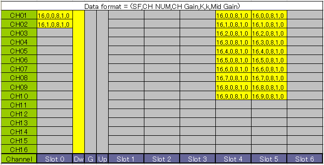
Ten SF 16 codes in each of Slot 4 and Slot 5 carry the downlink data.
The trace below shows bursts in S0, then S4 and S5 back to back, in every subframe.
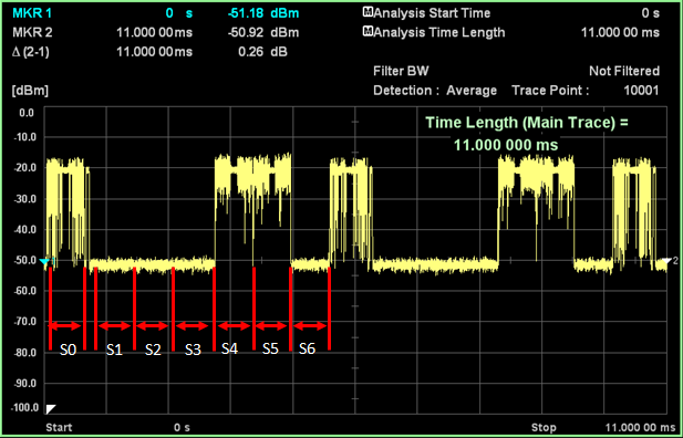
The downlink occupies S0, S4 and S5.
The code domain displays below are for TS0, TS4 and TS5. TS0 shows its power in the first two code positions. TS4 and TS5 each show ten codes at -10 dB. Ten equal codes that share the slot power are each 10 dB below the total.
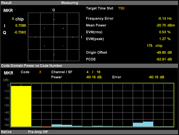
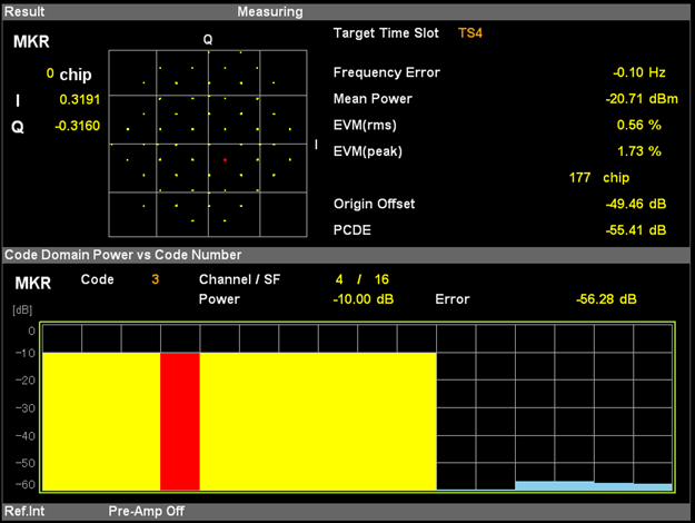
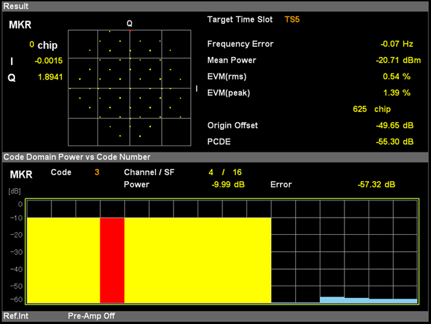
TS4 and TS5 each split the slot power over ten SF 16 codes.
This configuration differs from 25.102. Table A.4A allocates 2 TS with 8 x SF 16, which is 16 RU per 5 ms. The screens show 10 codes in each slot, which is 20 RU per 5 ms. The test setup therefore uses more codes than the 25.102 RMC for the same 144 kbps.
Downlink rate comes from code count : every downlink code is SF 16, so higher rates need more codes and slots.The screens show 20 RU, not 16 : 25.102 Table A.4A uses 8 codes per slot, while this setup uses 10.
RMC 384K - 1
This is a 384 kbps uplink configuration. It keeps the two-code layout of RMC 144K - 1 but spreads it over four slots, so the uplink takes most of the subframe.
The frame table below has entries in Slots 1 to 4. Each slot has CH01 as 2,0,-6.02,2,1,-6.02 and CH02 as 8,4,0,2,1,0. So compared with RMC 144K - 1, the gains are swapped: the SF 8 code is at 0 dB and the SF 2 code at -6.02 dB.
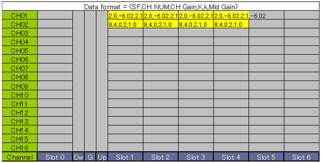
Four uplink slots, each with one SF 2 code and one SF 8 code.
The trace below shows one long burst over four slots in every subframe, with short dips at the slot boundaries.
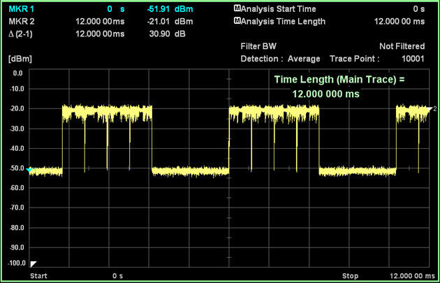
The uplink occupies four consecutive slots.
The code domain display below is for TS1. The SF 2 code fills 8 positions at -6.99 dB, and the SF 8 code fills 2 positions near the top of the scale. The same 4 to 1 power ratio applies as in RMC 144K - 1, now in the other direction.
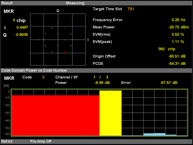
With swapped gains, the SF 8 code takes 80 % of the slot power.
With four uplink slots, the switch point from uplink to downlink moves to the end of Slot 4. Only Slots 5 and 6 are left for the downlink traffic after it.
Four uplink slots : Slots 1 to 4 each carry one SF 2 and one SF 8 code.Gains are swapped relative to 144K - 1 : here the SF 8 code has the higher power.Not a 25.102 RMC : 25.102 Annex A defines no 384 kbps uplink RMC.
RMC 384K - 2
This is the 384 kbps downlink configuration, the largest on the page. It fills four downlink slots with SF 16 codes, which moves the switch point close to the start of the subframe.
The frame table below shows Slot 0 with CH01 and CH02, and Slots 3 to 6 with ten SF 16 codes each, CH01 to CH10, all at 0 dB gain with K = 8.
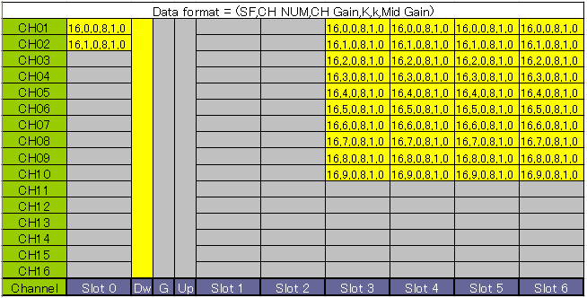
Four downlink slots, each with ten SF 16 codes.
The trace below shows a burst in S0 and a long burst over S3 to S6 in every subframe. So only S1 and S2 are left for the uplink.
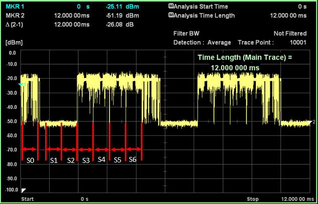
The downlink occupies S0 and S3 to S6.
The code domain displays below are for TS0 and TS3. TS0 again shows its power in the first two positions. TS3 shows ten codes at -9.99 dB, the same split as in RMC 144K - 2.
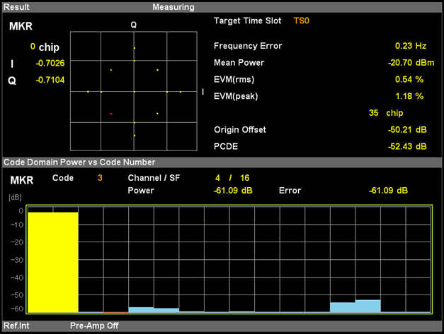
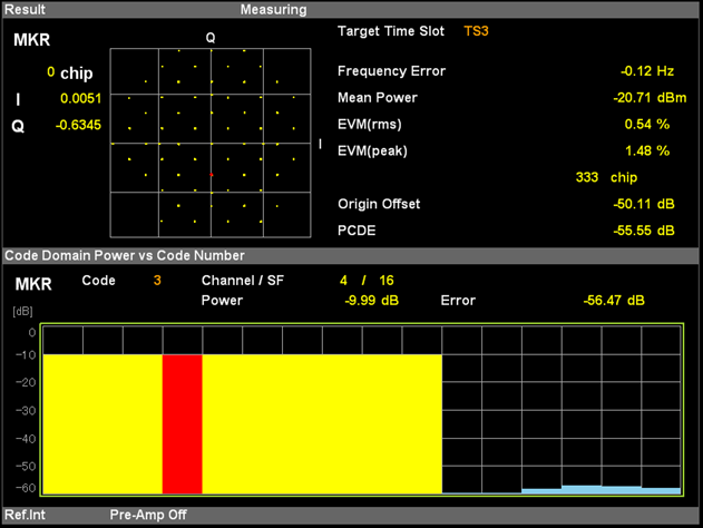
Each downlink traffic slot splits its power over ten SF 16 codes.
This configuration also differs from 25.102. Table A.5A allocates 4 TS with 9 x SF 16, which is 36 RU per 5 ms. The screens show 10 codes in each of the four slots, which is 40 RU per 5 ms.
Four downlink slots : Slots 3 to 6 carry the data, so the uplink keeps only Slots 1 and 2.The screens show 40 RU, not 36 : 25.102 Table A.5A uses 9 codes per slot, while this setup uses 10.
Reference
- 3GPP TS 25.102 v19.0.0 : User Equipment (UE) radio transmission and reception (TDD), Annex A.2, Tables A.1A, A.2A, A.4A and A.5A
- 3GPP TS 25.221 v19.0.0 : Physical channels and mapping of transport channels onto physical channels (TDD), subclauses 5.2.1, 5A.2 and 5A.3.1