MIMO/CA Big Picture
A couple of days ago I had a chat with one of my colleagues about overall antenna / system configuration for MIMO and Carrier Aggregation. After the chat, he asked me if I can recommend any books or technical papers that meets following criteria
- Minimized written description
- Easy enough so that any beginners can understand
I know these are the wishlist for anybody (including me) who tries to learn on any new technologies, but in reality it would be almost impossible to write a technical documents who perfectly meet these simple (?) criteria. 'Minimized written description' often omits a lot of details and omitting the details often need to sacrifice the accuracy. However, I think it is always worth trying to write this kind of document just to provide some big pictures for those who just got into the area even with sacrifice of some accuracy.
Since I don't recall any books and documents that I would recommend at the time, I decided to try writing my own version. I think I can easily meet the first criteria in this page, but no guarantee for the second criteria :)
Follwoings are the list of topics that I will cover in this page and I think (hope) this list will go on and on as I get more feedback from readers.
- What does it mean ? (Notation)
- How they are connected ?
- Connections in Test Equipment (eNB Simulator)
- Carrier Aggregation and MIMO
- Example : 2CC CA : 2x2, 2x2
- Example : 2CC CA : 4x4, 4x4
- Example : 3CC CA : 4x4,4x4,2x2
- Example : 5CC CA : 4x4,4x4,4x4,4x4,4x4
- Carrier Aggregation Band Combination : Intra vs Inter band
- TB(Transport Block), CW(Code Word), Layer
What does it mean ? (Notation)
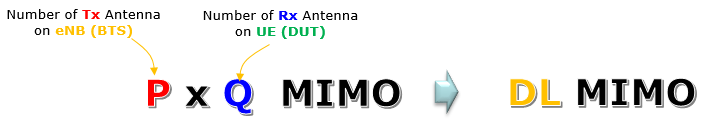
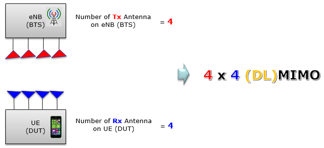
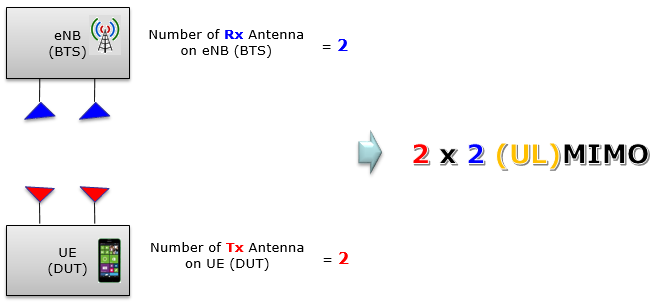
The first thing you need to get familiar with in learning any new technology is to get used to some termnilogy. In terms of MIMO, you might have heard so often of 2x2 MIMO, 4x4 MIMO, 4x2 MIMO etc. I think everybody would knows that MIMO stands for Multi Input Multi Output. Then you might ask 'what does Input mean and what is Output mean ?'. Technically Input / Output mean that Input mean the MIMO processor Input and Output mean the MIMO processor Output. Then you may ask what is the MIMO processor.. so this kind of Q&S would goes on and on. So just for the simplicity (with the sacrifice of a little bit of accuracy), think of Input as a transmittor antenna and output as reciever antenna.
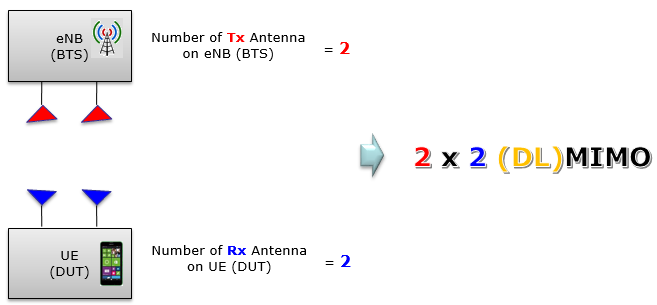
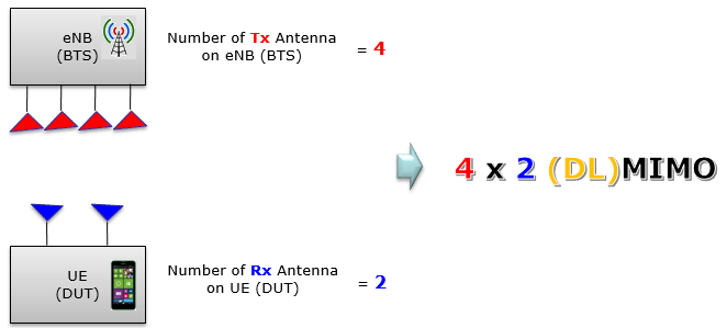
Then what does 2x2,4x2,4x4 mean .. those numbers indicates the number of Tx antenna and the number of Rx antenna as illustrated below. I don't think you would need any further explanation about this.

With this in mind, just go through some of the examples as shown below and see if they make sense to you
Now I think (hope) you got the general understanding on the MIMO antenna configuration. And then you may ask 'how the signal from the Tx antenna travel to Rx antenna'. Unfortunately this is not a question that can easily be answered. but I will try.
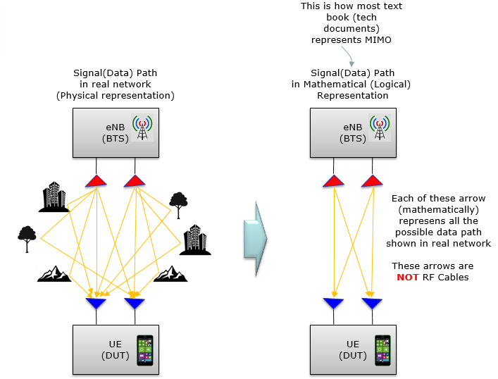
In live(real) network, the signal coming out of the Tx(Transmitter) antenna spread through every directions and reaching the Rx(Reciever) antenna via various different path as shown on the left side. Depending on the communication environment, the path would get more complicated or simpler. However, you wouldn't see this kind of connection diagram often in MIMO technical documents. What you would see in most of technical documents would be something like the one on the right side. However, the path on the right side is a kind of mathematical representation and it is not a physical representation. Don't think too much of the words 'mathematical connection' too much. Just think that each of the arrows indicates the possible signal flow from Tx to Rx antenna (Each of the single arrow has much more complicated meaning than you may think.. but I will not get any further into this. Because of these complexity, it is very difficult to implement the MIMO signal path using direct cable connection).
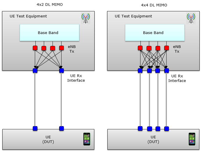
Connections in Test Equipment(eNB Simulator)
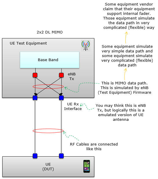
If you are just a MIMO user (e.g, mobile phone user), you wouldn't even care of how those Tx and Rx antenna are interacts. However, if you are involved in the industry of MIMO development and application, you would consider MIMO mostly in the context of simulated environment (e.g, Using eNB simulator and UE(DUT). Most of the MIMO test requires is done in conductive environment (i.e, in RF cable connection). However, as mentioned above it is very difficult (almost impossible) to implement the MIMO signal path by direct cable connection. Then how the equipment provide such a way that enables cable connection between eNB and UE(DUT) in MIMO setup ?
Taking 2x2 MIMO as a simple example, it can be illustrated as shown below (As far as I understand, most of UE test equipment in the market implement MIMO in similar way as explained here). As you see here, the MIMO path (mathematical MIMO path) is simulated inside the equipment and only the resulting output of the MIMO path are connected to the equipment RF port. You might have thought the RF port labeled as Out port on the equipment is not the Tx Antenna port in MIMO operation. Actually it functions as Rx Antenna port in MIMO diagram shown in previous section. So just connecting UE Rx port to the equipment Out port as shown below allows us to perform MIMO test with RF cable connection between DUT and the equipment. (Don't get disappointed even if this does not make clear sense to you right away. It would not be simple to understand. Just try to see this illustration several times with some interval (like several days or a couple of weeks), it will start making sense to you gradually).
By the same logic, 4x2 and 4x4 can be implemented as shown below. I hope these make sense to you.
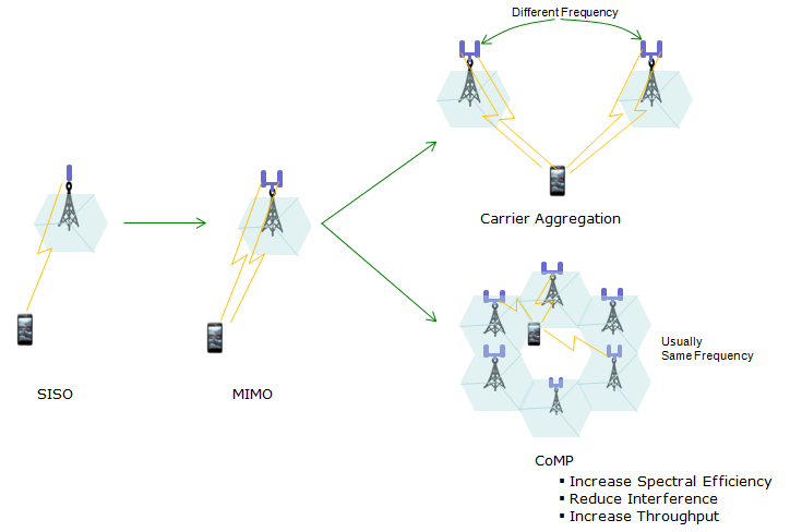
At a very high level view, Carrier Aggregatioin(CA) and MIMO has the same goal. It is to transmit the multiple data stream in parallel (i.e, simultaneosly) to achieve very high data throughput. The difference between MIMO and Carrier Aggregation. Actually there is another way of simultaneous throughput of multiple data stream, called CoMP(Coordinated multi-point operation). However, CoMP is not in the scope of this page (Refer to CoMP page if you are interested in ). Following illustration would would give you a comparative pictures on MIMO, CA, CoMP.
Just focusing on the comparision between MIMO and CA, you can say 'MIMO is the transmission of the multiple data stream within one eNB(BTS) via a same frequency and CA is the transmission of the multiple data stream using multiple eNB(BTS) with each eNB having different frequencies. In most case, MIMO and CA are used at the same time (i.e, Multiple eNB are transmitting multiple streams and each of the eNB in the CA setup is using MIMO).
Here goes some examples of CA with MIMO. I think (hope) the illustration itself would be self-explanatory. I wouldn't put any additional comments for each example to minimize reading :). Following examples are the most common CA/MIMO configurations that you might have seen (or hear about).
< Example : 2CC CA : 2x2, 2x2 >
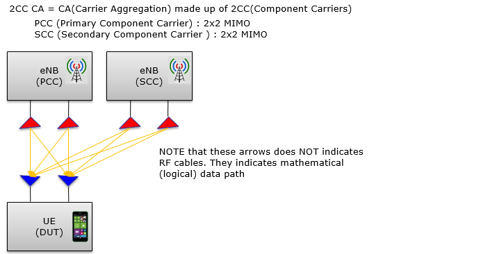
Examples of throughput estimation for this configuration are as follows :
< Example : 2CC CA : 4x4, 4x4 >
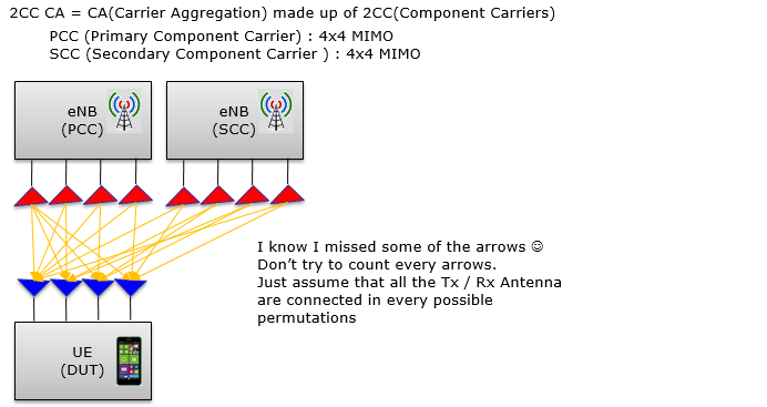
Examples of throughput estimation for this configuration are as follows :
< Example : 3CC CA : 4x4,4x4,2x2 >
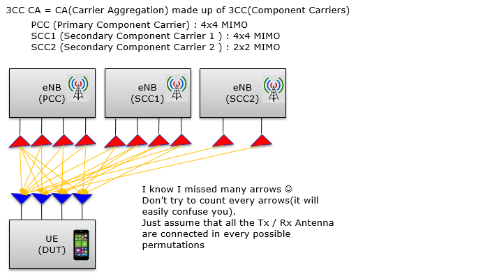
NOTE : It would be obvious on how each of antenna are mapped between eNB and UE when the number of eNB antenna and the number of UE antenna are same as in PCC and SCC1. Then you may ask how the antenna would map for SCC2 where the number of eNB antenna is smaller than the number of UE Rx antenna ? In this case, the two antenna from SCC2 are mapped to the first two antenna of the 4 UE antenna.
Examples of throughput estimation for this configuration are as follows :
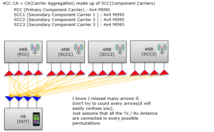
< Example : 4CC CA : 4x4,4x4,4x4,4x4 >
Examples of throughput estimation for this configuration are as follows :
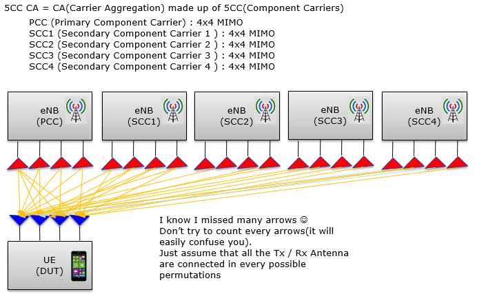
< Example : 5CC CA : 4x4,4x4,4x4,4x4,4x4 >
Carrier Aggregation Band Combination : Intra vs Inter band
Theoretically you can assign any frequency and any LTE Bandwidth for each CC(Component Carrier) for a CA(Carrier Aggregation) configuration. So if the number of CC in a CA gets larger the possible combination of carrier frequencies would go almost infinite. But 3GPP defines only a limited set of carrier combinations and the network operator would chose a specific combination from the 3GPP list(These list is defined in 3GPP TS 36.101). Even thought the list is too long for you to memorize, it would be helpful if you know of a couple of important pattern (categories) for carrier allocation.
In terms of carrier allocation pattern, you migh have heard often about 'intra band' or 'inter band'. Basically these terminology is used to describe the band allocation between two carriers. 'Inter' means 'between'. So 'Inter band' means 'between (different) bands' implying that all of the carriers belong to different band. 'Intra' means 'within'. So 'Intra band' means 'within a (same) band' implying that all of the carriers belong to a same band.
Intra band allocation has two different pattern called 'Intra band contiguous' and 'Intra band non-contiguous'. 'Contiguous' mean 'Sitting right next to each other' and you don't need any further explanation for 'Intra band non-contiguous'.
I think you would have pretty good understandings on carrier allocation pattern by now, but several examples illustrated as below would give you much clearer / intuitive understanding.
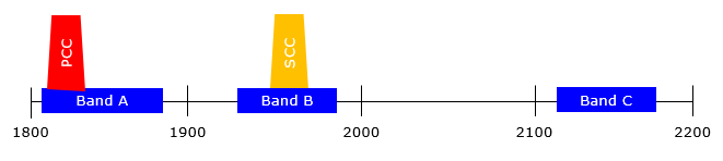
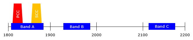
Example : 2CC CA - Inter band
Example : 2CC CA - Intra band, Non-contiguous
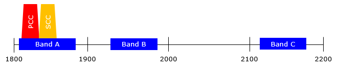
Example : 2CC CA - Intra band, contiguous
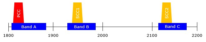
Example : 3CC CA - All carriers are in Inter band relationship.
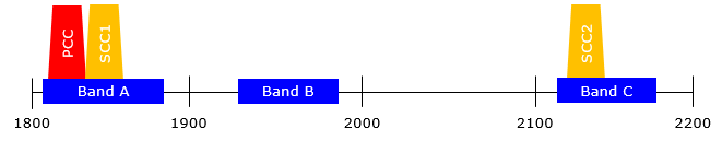
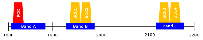
Example : 3CC CA - PCC and SCC1 are in intra band continguous relationship. PCC/SCC1 and SCC2 are in inter band relashionship.
Example : 5CC CA - (SCC1 and SCC1) and (SCC3 and SCC4) are in intra band continguous relationship. PCC and other bands are in inter band relashionship.
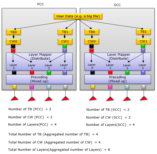
TB(Transport Block), CW(Code Word), Layer
The main reason I put this section is that some equipment vendor specifies their MIMO / CA capability in terms of Layers. For example, you may see the equipment description saying "Capable of supporting max 10 layers" etc.
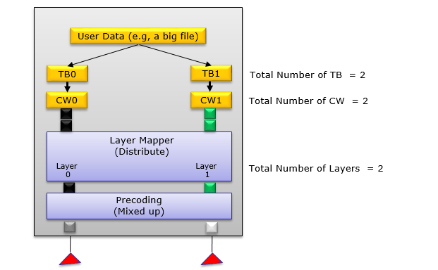
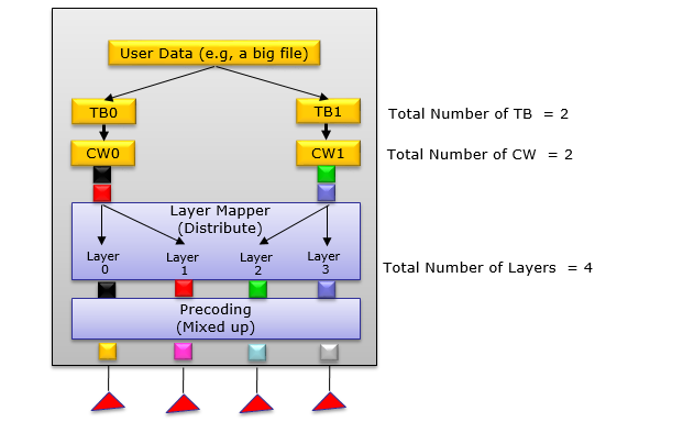
Followings are examples showing the overall data flow in MIMO / CA indicating the relationship among TB, CW, Layer (Detailed procedure of each steps are very complicated.. just follow through the terminologies for now).
NOTE : I often hear people talk about 'Stream', but it has a little bit vague meaning and people from different technical background may use it in a little bit different meaning. In LTE, Stream is often used as the same meaning as Layers, but be careful when you are talking to others.
NOTE : All of the illustrations shown below are showing the transmitter side only. It is assumed that the reciever side has the same number of Rx antenna)
NOTE : However many antenna are used in an eNB(BTS), the maximum number of TB(Transport Block) and CW(Codeword) are always 2.
Example : 2x2 MIMO
Example : 4x4 MIMO
Example : 2CC CA - 4x4 + 4x4 (PCC 4x4, SCC 4x4)