4G/LTE - Basic Procedures  


PDCCH (Physical Downlink Control Channel)

PDCCH is a physical channel that carries downlink control information (DCI) and it has characteristics as described below.

  • Mapped to the first L OFDM symbols in every downlink subframe.
  • Number of the symbols (L) for PDCCH can be 1,2, or 3. (This 'L' value is informed to UE by PCFICH)
  • Number of the symbols for PDCCH is specified by PCFICH
  • PDCCH carries DCIs and the DCI carries Transport format, resource allocation, H-ARQ information related to DL-SCH, UL-SCH and PCH.
  • PDCCH also carries DCI 0 which is for UL Scheduling assignment (e.g, UL Grants).
  • Multiple PDCCH are supported and a UE monitors a set of control channels.
  • Modulation Scheme is QPSK.
  • PDCCH is like HS-SCCH for HSDPA and PDCCH for R99, E-AGCH/E-RGCH for HSUPA
  • Even though PDCCH has a lot of functions, not all of them are used at the same time so PDCCH configuration should be done flexibly.
  • If you are interested in the detailed information mapping in this channel, refer to 6.8.1 of 36.211. Following is the initial descrition on this section.
    • The physical downlink control channel carries scheduling assignments and other control information. A physical controlchannel is transmitted on an aggregation of one or several consecutive control channel elements (CCEs), where acontrol channel element corresponds to 9 resource element groups. The number of resource-element groups not assigned to PCFICH or PHICH is REG N . The CCEs availablein the system are numbered from 0 and N_CCE-1 , where N_CCE = floor(N_REG/9) . The PDCCH supports multiple formats as listed in Table 6.8.1-1. A PDCCH consisting of nconsecutive CCEs may only start on a CCE fulfilling imod n = 0 , where i is the CCE number.

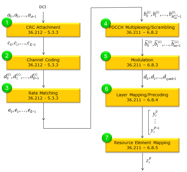
In terms of Channel Process, PDSCH goes through following steps. In case of PDCCH, the most complicated (also the confusing process) would be related to Step (7). Refer to CCE Index Calculation/PDCCH Decoding/Blind Decoding for the detailed process of how each bits of PDCCH symbols find its place in canditate area. Also refer to PDCCH Resource Allocation, and refer to PDCCH Candidate and Search Space for basic terminologies related to PDCCH resource allocation.

If you want to look into the final result of PDCCH resource allocation in visualized form as well as data processing process, refer to Matlab : Toolbox : PDCCH page.


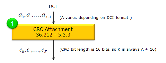
CRC Attachment

In LTE, PDCCH (Physical Downlink Control Channel) payloads use a 16-bit CRC for error detection (36.212-5.3.3.2). This design ensures the CRC not only provides error detection, but also implicitly encodes the target UE’s identity (the RNTI) and, if applicable, the chosen transmit antenna port. The CRC fails if a different RNTI or wrong antenna selection mask is assumed, preventing the UE from decoding control information not intended for it.

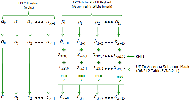
Overall procedure for CRC attachment for DCI can be summarized as bellow

  • Compute 16-bit CRC over the PDCCH payload (A bits).
  • Append these bits to form B = A + 16 total bits.
  • If no antenna selection is used, XOR the 16 CRC bits with the RNTI (xrnti).
  • If antenna selection is used (for DCI format 0), XOR the CRC bits with both RNTI (xrnti) and the antenna selection mask (xAS).
  • Transmit the resulting bits c0, ? cB-1 for the PDCCH.

Let A be the length of the PDCCH payload (a0, a1, …, aA−1). The CRC bits (p0, …, p15) are computed over all A bits and then appended, giving a total of B = A + 16 bits (b0, …, bB−1).

Once the 16 parity bits are attached, these bits can be scrambled using the RNTI (xrnti) and, optionally, an antenna-selection mask (xAS). This ensures the CRC is tied to a specific RNTI (and UE Tx antenna selection if applicable).

CRC Attachment

The CRC generator polynomial from Section 5.1.1 is used to derive the 16-bit CRC (p0 … p15) over the payload a0 … aA−1. These are appended to form:

b0, b1, …, bA−1, bA … bA+15

where bA+i = pi for i = 0..15.

Masking with RNTI

If UE Tx antenna selection is not enabled, the 16 CRC bits (bits bA … bA+15) are XOR-ed with the RNTI bits xrnti,0 … xrnti,15, where the MSB of the RNTI corresponds to xrnti,0. (This is the point where RNTI do the most important role)

Formally:

ck = bk for k < A ck = ( bk + xrnti, (k − A) ) mod 2 for k = A..(A+15)

This combines the CRC bits with the RNTI so that a receiver needs the correct RNTI to pass the CRC check.

When there is no UE Tx Antenna selection, CRC attachment and Masking goes as follows.

Additional Mask for Antenna Selection

When UE Tx antenna selection is configured, an extra mask xAS is applied — specifically for DCI format 0. In that case, each CRC bit bA..A+15 is XOR-ed with both xrnti and xAS:

ck = bk for k < A ck = ( bk + xrnti, (k − A) + xAS, (k − A) ) mod 2 for k = A..(A+15)

The mask xAS is defined in Table 5.3.3.2-1. For example, if UE port 1 is selected, xAS might be <0, …, 0, 1>, meaning only the least significant bit of the CRC is toggled.

< 38.212-Table 5.3.3.2-1: UE transmit antenna selection mask.>

UE transmit antenna selection

Antenna selection mask <xAS,0, xAS,1, …, xAS,15>

UE port 0

<0, 0, 0, 0, 0, 0, 0, 0, 0, 0, 0, 0, 0, 0, 0, 0>

UE port 1

<0, 0, 0, 0, 0, 0, 0, 0, 0, 0, 0, 0, 0, 0, 0, 1>

When there is UE Tx Antenna selection, CRC attachment and Masking goes as follows.

NOTE :How 'A' is determined ?

In LTE, A represents the number of bits in the PDCCH payload (the DCI message) before the CRC is attached. Its exact size depends on the chosen DCI format and the number of bits needed to represent each field within that format (e.g., frequency allocation, modulation and coding scheme, HARQ process number, etc.).

Example: DCI Format 0

Consider a scenario where DCI format 0 is used for uplink grants. The payload might include the following fields:

  • Frequency-domain resource allocation (e.g., 10 bits)
  • Modulation and coding scheme (e.g., 5 bits)
  • HARQ process number (e.g., 3 bits)
  • New data indicator (1 bit)
  • Redundancy version (2 bits)
  • Transmission power control command for uplink (2 bits)
  • … and possibly other fields depending on the specific system configuration.

Adding these up (except the variable fields in this example), you may end up with, say, 27 bits in total. In that case, A = 27. Once determined, a 16-bit CRC is appended, resulting in a final codeword of A + 16 bits (i.e., 27 + 16 = 43 bits).

Channel Coding 

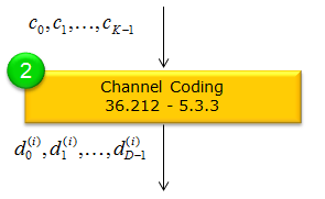
In LTE, Downlink Control Information (DCI) messages on the PDCCH are channel-coded with a tail-biting convolutional code at rate 1/3 (36.212-5.3.3.3).

< Table 5.1.3-2 of TS36.212 >

The defailed breakdown are as follows:

  • Input Bits (c0, …, cK−1) The PDCCH payload (after CRC attachment) forms a block of K bits, denoted c0, c1, …, cK−1. These bits become the input to the tail-biting convolutional encoder.
  • Tail-Biting Convolutional Encoder LTE’s DCI uses a rate-1/3 convolutional encoder with tail-biting initialization. That means:
    • The encoder “wraps around” so that its end state matches its start state without adding extra tail bits.
    • Each input bit ck produces three output bits d(0)k, d(1)k, d(2)k.
  • Output Bits (d(i)k) Because it is a rate-1/3 code, for every one input bit, you get three output streams. Each stream d(i) has exactly D = K bits, so the total number of coded bits is 3 × K. Symbolically, we write them as d(i)0, d(i)1, …, d(i)D−1 where i = 0, 1, 2 and D = K.

After these coded bits are generated, they are passed on to the next step (rate matching) and then eventually mapped to the PDCCH resources. Tail-biting convolutional coding ensures minimal overhead while preserving robust forward error correction for DCI payloads.

NOTE : In essence it follows the same tail-biting convolutional procedure (rate 1/3) as used for the PBCH. The main difference is simply the input bit length and how those bits are processed or repeated for each channel. But the core “encode one bit → produce three output bits, with tail-biting to avoid appending extra tail bits” is identical. Refer to BCH channel coding for further details.

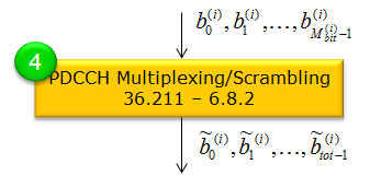
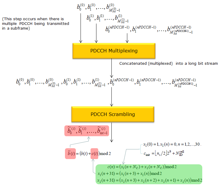
Multiplexing/Scrambling


c(i) here is a Gold Sequence. If you are not familiar with the concept of a Gold Sequence, refere to GoldCode page.

PDCCH Encoding in srsRAN

If you are interested in this process at the source code level of the protocol stack, I would suggest you to look into the openSource srsRAN. Following APIs can be good places for you to start. This list is from the master-branch of the code that was downloaded on Oct 8,2021

  •   srsran_rm_conv_tx() -> \lib\src\phy\fec\turbo\rm_conv.c
  •   srsran_convcoder_encode() -> \lib\src\phy\fec\convolutional\convcoder.c
  •   srsran_pdcch_dci_encode_conv() -> \lib\src\phy\phch\pdcch.c
  •   srsran_pdcch_dci_encode() -> \lib\src\phy\phch\pdcch.c
  •   srsran_scrambling_b_offset() -> \lib\src\phy\scrambling\scrambling.c
  •   srsran_mod_modulate() -> \lib\src\phy\modem\mod.c
  •   srsran_layermap_diversity() -> \lib\src\phy\mimo\layermap.c
  •   srsran_precoding_diversity() -> \lib\src\phy\mimo\precoding.c
  • srsran_regs_pdcch_put_offset() -> \lib\src\phy\phch\regs.c
  •   srsran_pdcch_encode() -> \lib\src\phy\phch\pdcch.c

PDCCH Decoding in srsRAN

If you are interested in this process at the source code level of the protocol stack, I would suggest you to look into the openSource srsRAN. Following APIs can be good places for you to start. This list is from the master-branch of the code that was downloaded on Oct 8,2021

  •   srsran_crc_checksum() -> \lib\src\phy\fec\crc.c
  •   srsran_bit_pack() -> \lib\src\phy\utils\bit.c
  •   srsran_viterbi_decode_f() -> \src\phy\fec\convolutional\viterbi.c
  •   srsran_rm_conv_rx() -> \lib\src\phy\fec\turbo\rm_conv.c
  •   srsran_pdcch_dci_decode() -> \lib\src\phy\phch\pdcch.c
  •   srsran_pdcch_decode_msg() -> \lib\src\phy\phch\pdcch.c