CCE Index Calculation
CCE Index is the CCE number at which the control channel data (PDCCH) is allocated. Normally this index changes for each subframe, meaning that even the same PDCCH data (e.g, a PDCCH for the same UE) allocated in each subframe changes subframe by subframe. (If you are not familiar with what is CCE, refer to Resource Element Management section first.)
One of the most common situations where you have to care about this CCE index is when you change the system BW. Changing the system bandwidth in higher layer (L3) is very simple. You only have to change one IE in MIB, but if you are a protocol stack developer or test case developer who take care of all stack from L1 through L3, you have to calculate CCE index for each subframe and those index gets different for each bandwidth. But calculating CCE is not a simple procedure. Just outline of the calculation is as follows. Just try to have an idea on which parameters you need and how they are related to calculate CCE.
- CCE Index Calculation Procedure
- PDCCH Decoding/Blind Decoding on UE side
- Live Examples
- Why so complex ?
CCE Index Calculation Procedure
Followings are the brief summary of the procedures of calculating the CCE Index. (I would recommend you to refer to Ref [2] for further details and different way of explanation)
Step 1 : Figure out all the REs within the Control region (the first 1 or 2 or 3 OFDM symbols) that can be reserved for PDCCH allocation. (Note : item (iii), (iv) are only in the first OFDM symbol. Item (ii) is located in multiple OFDM symbols, but within the control region it is also located only in the first OFDM symbol. Refer to Downlink Frame Structure page for the details of each channel allocation in RB map)
RE's for PDCCH = Total Available RE's within control symbols -------(i)
- Number of RE's used for reference signals -------(ii)
- Number of RE's used in PHICH -------------------(iii)
- Number of RE's used in PCFICH ------------------(iv)
Step 2 : Figure out total number CCE's available for PDCCH.
total number CCE's available for PDCCH = (The Result of Step 1)/36, since 1 CCE = 36 REs
Step 3 : Number each of the CCEs from the result of Step 2. (Number starts from 0).
Step 4 : eNB decide CCE index according to following formula (Note : Depending on Aggregation Level(L), you will get the different number of consecutive CCEs for allocating one PDCCH. For example, if L is 1, 'i' can be only '0'. So you have only one CCE for the PDCCH. If L = 4, you will have for CCE index by plugging 0,1,2,3 into the variable 'i'. Then you will have four consecutive CCE index. It means one PDCCH will be spread over the four consecutive CCEs).
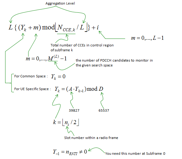
Following is an Example of CCE index calculation. First try calculating the values on your own according to the descriptions above (Step 4) and compare your result with my result (Excel Spreadsheet is also linked here). The cell in green is the parts that should be derived/calculated from other cells. (Note : In this example, I assumed the case where 100 CCEs are available. But in reality, there is no such a case where you can have 100 CCE. To have 100 CCEs, you need 3600 RE (=36 RE/CCE * 100 CCE). In case of 20 Mhz Bandwidth, CFI = 3. You have 3600 RE in Control Region, but you have remove those REs for Reference Signal, PCFICH and PHICH. So the available REs for CCE become less than 100 CCE. Refer to Ref [1] for the details of calculating the available CCEs)
| L (Aggregation Level) |
1 |
|||
|
C_RNTI(n_RNTI) |
100 |
|||
|
i (0~[Aggregation Level-1]) |
0 |
|||
|
m' (0 ~ [Number of PDCCH Candidate-1]) |
1 |
|||
|
A |
39827 |
|||
|
D |
65537 |
|||
|
k (subframe) |
Y(k-1) |
Y(k) |
N_CCE |
CCE Index |
|
0 |
100 |
50480 |
100 |
81 |
|
1 |
50480 |
53948 |
100 |
49 |
|
2 |
53948 |
21988 |
100 |
89 |
|
3 |
21988 |
10682 |
100 |
83 |
|
4 |
10682 |
31347 |
100 |
48 |
|
5 |
31347 |
42656 |
100 |
57 |
|
6 |
42656 |
10398 |
100 |
99 |
|
7 |
10398 |
58380 |
100 |
81 |
|
8 |
58380 |
44111 |
100 |
12 |
|
9 |
44111 |
23975 |
100 |
76 |
(Click here to get excel spreadsheet)
For further details of the procedure, refer to TS 36.213 - 9.1.1 PDCCH Assignment Procedure.
Too complicated ? If you are not the person who has to implement this algorithm in your chipset, just try to understand the basic idea explained below.
PDCCH Decoding/Blind Decoding on UE side
UE has 'ALMOST' no information for decoding PDCCH. So UE has to try 'ALL' the possible tries to decode PDCCH. This is called 'Blind Decoding'.
For example, let's look into all the possible combinations to try for Common Search Space and assume the total space is 16 CCEs. Following is factors and number of combinations.
i) All the possible blocks assuming Aggregation Level 4 = 16 (CCE) / 4 (Aggregation Level) = 4 blocks
ii) All the possible blocks assuming Aggregation Level 2 = 16 (CCE) / 8 (Aggregation Level) = 2 blocks
iii) All the possible DCI formats supported for common space = assuming 2 (out of 0,1A,3,3A,1C based on TM)
----------------------------------------------------------------------------------------------
Total number of decoding tries = ( i + ii) x iii = (4 + 2) x 2 = 12
After all of these blind trials, UE checks CRC with all the possible RNTIs it can be applicable.
Live Example of CCE Allocation
Following is a example of CCE index calculation (CCE Allocation for PDCCH) in real communication between UE and eNB simulator from Amarisoft Callbox. (This is the example with the case of BandWidth = 5Mhz, CFI = 3, C_RNTI = 0x61)
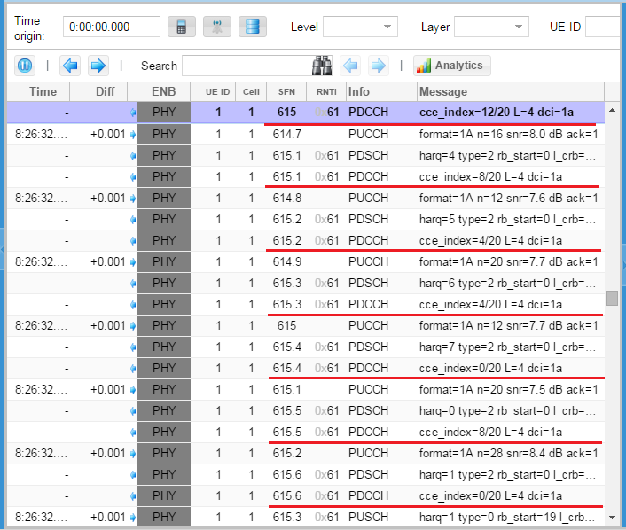
Following is the CCE index from the log shown above and presented in a tabular form. See if you can find a kind of pattern.
|
SFN |
Subframe |
AggregationLevel |
Total CCE |
CCE Index |
DCI Format |
|
615 |
0 |
4 |
20 |
12 |
1A |
|
615 |
1 |
4 |
20 |
8 |
1A |
|
615 |
2 |
4 |
20 |
4 |
1A |
|
615 |
3 |
4 |
20 |
4 |
1A |
|
615 |
4 |
4 |
20 |
0 |
1A |
|
615 |
5 |
4 |
20 |
8 |
1A |
|
615 |
6 |
4 |
20 |
0 |
1A |
|
615 |
7 |
4 |
20 |
8 |
0 |
|
615 |
7 |
4 |
20 |
12 |
1A |
|
615 |
8 |
4 |
20 |
16 |
1A |
|
615 |
9 |
4 |
20 |
16 |
1A |
|
616 |
0 |
4 |
20 |
12 |
1A |
|
616 |
1 |
4 |
20 |
8 |
1A |
|
616 |
2 |
4 |
20 |
4 |
1A |
|
616 |
3 |
4 |
20 |
4 |
1A |
|
616 |
4 |
4 |
20 |
0 |
1A |
|
616 |
5 |
4 |
20 |
8 |
0 |
|
616 |
5 |
4 |
20 |
12 |
1A |
|
616 |
6 |
4 |
20 |
0 |
0 |
|
616 |
6 |
4 |
20 |
4 |
1A |
|
616 |
7 |
4 |
20 |
8 |
1A |
|
616 |
8 |
4 |
20 |
16 |
1A |
|
616 |
9 |
4 |
20 |
16 |
1A |
Following is another presentation of CCE index allocation in tabular form. You will see 4 consecutive CCE allocation for each PDCCH. This is because AggregationLevel in this example is 4. The CCE Index calculated at each subframe indicates the first CCE number of the four consecutive CCEs.
|
SFN |
Sub frame |
CCE Index |
0 |
1 |
2 |
3 |
4 |
5 |
6 |
7 |
8 |
9 |
10 |
11 |
12 |
13 |
14 |
15 |
16 |
17 |
18 |
19 |
|
615 |
0 |
12 |
||||||||||||||||||||
|
615 |
1 |
8 |
||||||||||||||||||||
|
615 |
2 |
4 |
||||||||||||||||||||
|
615 |
3 |
4 |
||||||||||||||||||||
|
615 |
4 |
0 |
||||||||||||||||||||
|
615 |
5 |
8 |
||||||||||||||||||||
|
615 |
6 |
0 |
||||||||||||||||||||
|
615 |
7 |
8 |
||||||||||||||||||||
|
615 |
7 |
12 |
||||||||||||||||||||
|
615 |
8 |
16 |
||||||||||||||||||||
|
615 |
9 |
16 |
||||||||||||||||||||
|
616 |
0 |
12 |
||||||||||||||||||||
|
616 |
1 |
8 |
||||||||||||||||||||
|
616 |
2 |
4 |
||||||||||||||||||||
|
616 |
3 |
4 |
||||||||||||||||||||
|
616 |
4 |
0 |
||||||||||||||||||||
|
616 |
5 |
8 |
||||||||||||||||||||
|
616 |
5 |
12 |
||||||||||||||||||||
|
616 |
6 |
0 |
||||||||||||||||||||
|
616 |
6 |
4 |
||||||||||||||||||||
|
616 |
7 |
8 |
||||||||||||||||||||
|
616 |
8 |
16 |
||||||||||||||||||||
|
616 |
9 |
16 |
When I first try to understand and configure CCE index at early phase of verification, the first question poping up in my mind was "Why is it designed in such a complicated manner to determine the CCE Index (Location of PDCCH allocation) ?".
Of course (and unfortunately) 3GPP specification never tell you "Why ?", it says only "What". I think you can get this "Why" part from various TDocs related to this issue. Following is from "2.1 Requirements of R1-072470" and blue part is my comments.
•Possibility for interference randomization between cells. A certain control channel should not persistently collide with one and the same control channel in a neighboring cell. --> This is why we assign different CCE Index for every subframe.
•Possibility for interference coordination. By using different parts of the frequency spectrum in different cells for control signaling it should be possible to avoid/reduce inter-cell interference for the control channels.
•As seen from the UE, the CCE-to-RE mapping structure should be invariant to whether interference coordination is used or not. After the cell-search procedure, the UE does not know whether a cell is applying interference coordination or not but still needs to read system information from the “dynamic BCCH”. If the “dynamic BCCH” is mapped to the DL-SCH (or transmitted in a similar way as the DL-SCH), it must be possible to read the DL-SCH and associated control signaling without knowledge about any inter-cell coordination.
•Control signaling should utilize the full system bandwidth to exploit any frequency diversity (already agreed in RAN1). --> This is why the total number of RBs for the full system bandwidth is used as a parameters in the CCE index determination algorithm.
•Two symbols from the same CCE should be mapped to two in frequency neighboring REs in order to support SFBC as the diversity scheme (already agreed inRAN1).
Reference :
[1] PDCCH Dimensioning (LTE University)
[2] All about PDCCH and CCE allocation (Tayal's way to learn LTE)