SRS is the UL reference signal that the eNB uses to measure the channel of a UE, including RBs that the UE is not using yet. This page goes from why SRS exists, to how often it is sent and how RRC configures it, and then to signal generation and one real log.
SRS stands for Sounding Reference Signal. Literally it says a kind of "Reference Signal".
Reference Signal for who ? Is it for UE or for eNodeB ? It is reference signal for eNodeB to figure out the channel quality of uplink path for each subsections of frequence region.
Who is sending this reference signal ? It is UE. (You may remember from Uplink Framestructure section that UE is transmitting SRS at the last symbol of a subframe)
To be precise about the position, 36.211 clause 5.5.3 says that the sounding reference signal shall be transmitted in the last symbol of the uplink subframe. In TDD, SRS can also be sent in UpPTS of the special subframe. Every other property of SRS comes from RRC configuration: which subframes, how many RBs, which comb, which cyclic shift, and whether it hops.
Followings are the topics to be covered in this page.
- Why SRS ?
- How often SRS is transmitted ?
- Rrc Parameters for SRS
- SRS Signal Generation
- SRS and Short/Normal PUSCH
- Example 01
- Reference
Why SRS ?
Why we need this kind of signal ? As you know, in LTE eNodeB often allocates only a partial section of full system bandwidth for a specific UE and at a specific time. So it would be good to know which section across the overall bandwidth has better channel quality comparing to the other region. In this case, Network can allocate the specific frequency region which is the best for each of the UEs. (If we always have to use full bandwidth, we may not need this kind of reference signal since there is no choice even when there is a better or worse spots within the bandwidth).
The UL already has DMRS, so why do we need another reference signal ? The reason is the bandwidth. DMRS for PUSCH is sent only in the RBs that the UE is scheduled on, so the eNB learns nothing about the other RBs. SRS is not tied to a PUSCH or PUCCH transmission, so the eNB can configure it over RBs that the UE is not using yet. That is exactly the information the scheduler needs for frequency selective scheduling in the UL.
36.213 clause 8.2 gives SRS several trigger types. Trigger type 0 is configured by higher layer signalling. This is the periodic SRS that most of this page describes. Trigger type 1 is triggered by DCI, for example DCI format 0, 4 or 1A in FDD and TDD, and DCI format 2B, 2C or 2D in TDD. This aperiodic SRS was added in Release 10. If a trigger type 0 and a trigger type 1 SRS fall in the same subframe of the same serving cell, the UE transmits only the trigger type 1 SRS.
SRS sounds RBs that are not scheduled : DMRS covers only the scheduled RBs, and SRS covers the configured SRS bandwidth.SRS feeds the UL scheduler : the eNB uses it to choose the RBs with the better channel for each UE.SRS can be periodic or aperiodic : trigger type 0 comes from RRC and trigger type 1 comes from DCI.
How often SRS is transmitted ?
SRS timing is set at two levels, and it is easy to mix them. The cell decides in which subframes any UE may send SRS, and each UE gets its own period and offset inside that set.
How often UE transmit SRS ?
It depends on the configuration set by the signaling message (SIB2, RRC Connection Setup, RRC Connection Reconfiguration etc), but UE can transmit it every two subframes at the most and every 32 frame (320 subframe) at the least (10 bit signaling parameter srs-ConfigIndex tells UE of the periodicity of SRS transmission and the period can be 2,5,10,20,40,80,160,320 ms). Actually there is an option in which UE does not transmit SRS at all.
SRS is transmitted at the last symbol of UL subframe over the SRS bandwidth set by srs-BandwidthConfig and srs-Bandwidth, and it is transmitted by a certain interval. What if multiple UE has the same SRS transmission cycle(interval) ? Would there be any possibility that a bunch of SRS from multiple UEs are overlapped ?
Yes, this is possible. To avoid this kind of situation, we can configure each of UE to transmit SRS in hopping mode with different hopping schedule.
Let's separate the two levels. The cell-specific level is srs-SubframeConfig in SIB2, which marks the SRS subframes of the cell through 36.211 Table 5.5.3.3-1 for FDD and Table 5.5.3.3-2 for TDD. The UE-specific level is srs-ConfigIndex, which gives the UE its own period TSRS and offset Toffset through 36.213 Table 8.2-1 for FDD and Table 8.2-2 for TDD. Also, the duration field decides whether the UE sends a single SRS or keeps sending until SRS is disabled.
Hopping is not the only way to keep UEs apart. UEs that send SRS in the same symbol can also use a different transmissionComb, which selects every other subcarrier, or a different cyclicShift, cs0 to cs7. They can also use a different freqDomainPosition. So the eNB has comb, cyclic shift and frequency position to multiplex many UEs in one SRS symbol.
The cell sets the SRS subframes : srs-SubframeConfig in SIB2 defines which subframes can carry SRS.The UE gets its own period : srs-ConfigIndex gives 2 ms to 320 ms and an offset.duration decides single or periodic : FALSE means a single SRS, and TRUE means indefinite until disabled.Comb and cyclic shift separate UEs : two UEs can share an SRS symbol without hopping.
Rrc Parameters for SRS
As I mentioned earlier, SRS configuration is notified to UE by a couple of RRC messages. Common RRC messages carrying SRS configuration info are SIB2, RRC Connection Setup, RRC Connection Reconfiguration.
There are largerly two kinds of SRS, Common SRS and Dedicated SRS. Common SRS is also called Cell Specific SRS and Dedicated SRS is also called UE Specific SRS.
In SIB2, SRS is configured in following information elements. You can disable SRS by setting soundingRS-UL-ConfigCommon if you want.
Decoded RRC message,
            |     +-radioResourceConfigCommon ::= SEQUENCE
            |     | +-rach-ConfigCommon ::= SEQUENCE
            |     | +-bcch-Config ::= SEQUENCE
            |     | +-pcch-Config ::= SEQUENCE
            |     | +-prach-Config ::= SEQUENCE
            |     | +-pdsch-ConfigCommon ::= SEQUENCE
            |     | +-pusch-ConfigCommon ::= SEQUENCE
            |     | +-pucch-ConfigCommon ::= SEQUENCE
            |     | +-soundingRS-UL-ConfigCommon ::= CHOICE [setup]
            |     | | +-setup ::= SEQUENCE [0]
            |     | |   +-srs-BandwidthConfig ::= ENUMERATED [bw2]
            |     | |   +-srs-SubframeConfig ::= ENUMERATED [sc0]
            |     | |   +-ackNackSRS-SimultaneousTransmission ::= BOOLEAN [TRUE]
            |     | |   +-srs-MaxUpPts ::= ENUMERATED OPTIONAL:Omit
            |     | +-uplinkPowerControlCommon ::= SEQUENCE
            |     | +-ul-CyclicPrefixLength ::= ENUMERATED [len1]
In RRC Connection Setup and RRC Connection Reconfiguration, SRS is configured in following information elements. You can disable SRS by setting soundingRS-UL-ConfigDedicated if you want.
Decoded RRC message,
              | +-physicalConfigDedicated ::= SEQUENCE [0000110110] OPTIONAL:Exist
              |   +-pdsch-ConfigDedicated ::= SEQUENCE OPTIONAL:Omit
              |   +-pucch-ConfigDedicated ::= SEQUENCE OPTIONAL:Omit
              |   +-pusch-ConfigDedicated ::= SEQUENCE OPTIONAL:Omit
              |   +-uplinkPowerControlDedicated ::= SEQUENCE OPTIONAL:Omit
              |   +-tpc-PDCCH-ConfigPUCCH ::= CHOICE [setup] OPTIONAL:Exist
              |   +-tpc-PDCCH-ConfigPUSCH ::= CHOICE [setup] OPTIONAL:Exist
              |   +-cqi-ReportConfig ::= SEQUENCE OPTIONAL:Omit
              |   +-soundingRS-UL-ConfigDedicated ::= CHOICE [setup] OPTIONAL:Exist
              |   | +-setup ::= SEQUENCE
              |   |   +-srs-Bandwidth ::= ENUMERATED [bw0]
              |   |   +-srs-HoppingBandwidth ::= ENUMERATED [hbw0]
              |   |   +-freqDomainPosition ::= INTEGER (0..23) [0]
              |   |   +-duration ::= BOOLEAN [FALSE]
              |   |   +-srs-ConfigIndex ::= INTEGER (0..1023) [0]
              |   |   +-transmissionComb ::= INTEGER (0..1) [0]
              |   |   +-cyclicShift ::= ENUMERATED [cs0]
              |   +-antennaInfo ::= CHOICE [explicitValue] OPTIONAL:Exist
              |   +-schedulingRequestConfig ::= CHOICE OPTIONAL:Omit
The two captures above show the field names as a tester decodes them. The listing below gives the same two IEs as 36.331 v19.3.0 defines them, together with the Release 10 extension that adds the number of SRS antenna ports.
Following is based on
SoundingRS-UL-ConfigCommon ::=      CHOICE {
    release                             NULL,
    setup                               SEQUENCE {
        srs-BandwidthConfig                 ENUMERATED {bw0, bw1, bw2, bw3, bw4, bw5, bw6, bw7},
        srs-SubframeConfig                  ENUMERATED {
                                                sc0, sc1, sc2, sc3, sc4, sc5, sc6, sc7,
                                                sc8, sc9, sc10, sc11, sc12, sc13, sc14, sc15},
        ackNackSRS-SimultaneousTransmission BOOLEAN,
        srs-MaxUpPts                        ENUMERATED {true}           OPTIONAL    -- Cond TDD
    }
}

SoundingRS-UL-ConfigDedicated ::=   CHOICE{
    release                             NULL,
    setup                               SEQUENCE {
        srs-Bandwidth                       ENUMERATED {bw0, bw1, bw2, bw3},
        srs-HoppingBandwidth                ENUMERATED {hbw0, hbw1, hbw2, hbw3},
        freqDomainPosition                  INTEGER (0..23),
        duration                            BOOLEAN,
        srs-ConfigIndex                     INTEGER (0..1023),
        transmissionComb                    INTEGER (0..1),
        cyclicShift                         ENUMERATED {cs0, cs1, cs2, cs3, cs4, cs5, cs6, cs7}
    }
}

SoundingRS-UL-ConfigDedicated-v1020 ::= SEQUENCE {
    srs-AntennaPort-r10                 SRS-AntennaPort
}

SRS-AntennaPort ::=                 ENUMERATED {an1, an2, an4, spare1}
The Release 8 IEs have not changed. Later releases added new IEs next to them instead. SoundingRS-UL-ConfigDedicated-v1020 carries srs-AntennaPort-r10, the number of antenna ports for SRS, which can be 1, 2 or 4. SoundingRS-UL-ConfigDedicatedAperiodic-r10 configures the aperiodic SRS of trigger type 1. Release 13 added SRS in the extended UpPTS for TDD, and Release 16 added additional SRS symbols through SoundingRS-UL-ConfigDedicatedAdd-r16.
For srs-Bandwidth, refer to following tables from 36.211. Basically these tables defines how many resource block (frequency bandwidth) is allocated for SRS transmission.
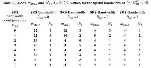
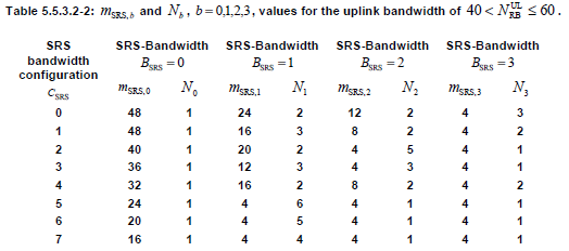
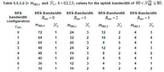
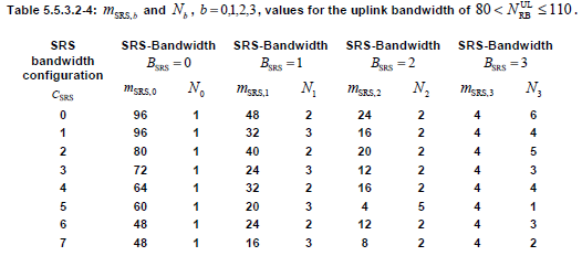
An example of how to interpret the above table is as follows.
< Interpretation of SRS configuration Table - Example >
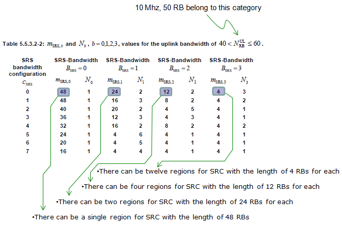
The example above reads one row of Table 5.5.3.2-2, which applies to a 50 RB uplink. With CSRS = 0, BSRS = 0 gives one region of 48 RBs, BSRS = 1 gives two regions of 24 RBs, BSRS = 2 gives four regions of 12 RBs, and BSRS = 3 gives twelve regions of 4 RBs. The notes in the picture write SRC, which means SRS.
If I convert the above description, it can be illustrated as shown below.
< Visual Interpretation of SRS configuration Table - Example >
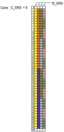
Each column of the diagram above is one value of BSRS, from 0 on the left to 3 on the right, over RB 0 to RB 49. The 48 RBs of the SRS bandwidth leave one RB free at each edge of the 50 RB uplink, where PUCCH normally sits. The colours in each column mark the regions described above.
For srs-SubframeConfig, please refer to the following table from 36.211. Since srs-SubframeConfig is parameter only for SRS Common (Cell Specific SRS), this table is applied only for Cell Specific SRS. Basically this table defines on which subframe SRS is transmitted and on which subframe it is not transmitted.

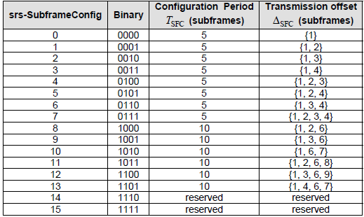
How do we know from the table above, which subframe should transmit SRS or which subframe should not ? It is determined by the following rule.

, where ns here means "slot number within a radio frame".
For example, if we chose subframe configuration 7, T_SFC become 5 and Delta_SFC become {0,1}. According to this, the SRS Status on each subframe become as follows.
|
Subframe Number |
ns |
Floor[ns/2] mod T_SFC |
SRS Status |
|
0 |
0 |
Floor[0/2] mod 5 = 0 |
The result is a member of {0,1}, so SRS is ON |
|
1 |
Floor[1/2] mod 5 = 0 |
||
|
1 |
2 |
Floor[2/2] mod 5 = 1 |
The result is a member of {0,1}, so SRS is ON |
|
3 |
Floor[3/2] mod 5 = 1 |
||
|
2 |
4 |
Floor[4/2] mod 5 = 2 |
The result is not a member of {0,1}, so SRS is OFF |
|
5 |
Floor[5/2] mod 5 = 2 |
||
|
3 |
6 |
Floor[6/2] mod 5 = 3 |
The result is not a member of {0,1}, so SRS is OFF |
|
7 |
Floor[7/2] mod 5 = 3 |
||
|
4 |
8 |
Floor[8/2] mod 5 = 4 |
The result is not a member of {0,1}, so SRS is OFF |
|
9 |
Floor[9/2] mod 5 = 4 |
||
|
5 |
10 |
Floor[10/2] mod 5 = 0 |
The result is a member of {0,1}, so SRS is ON |
|
11 |
Floor[11/2] mod 5 = 0 |
||
|
6 |
12 |
Floor[12/2] mod 5 = 1 |
The result is a member of {0,1}, so SRS is ON |
|
13 |
Floor[13/2] mod 5 = 1 |
||
|
7 |
14 |
Floor[14/2] mod 5 = 2 |
The result is not a member of {0,1}, so SRS is OFF |
|
15 |
Floor[15/2] mod 5 = 2 |
||
|
8 |
16 |
Floor[16/2] mod 5 = 3 |
The result is not a member of {0,1}, so SRS is OFF |
|
17 |
Floor[17/2] mod 5 = 3 |
||
|
9 |
18 |
Floor[18/2] mod 5 = 4 |
The result is not a member of {0,1}, so SRS is OFF |
|
19 |
Floor[19/2] mod 5 = 4 |
Following is an example frame structure showing the SRS transmission determined by the above table. (In this example, System BW = 5 Mhz, Start RB = 5, Number of RB = 15)
< Uplink Frame Structure with SRS >
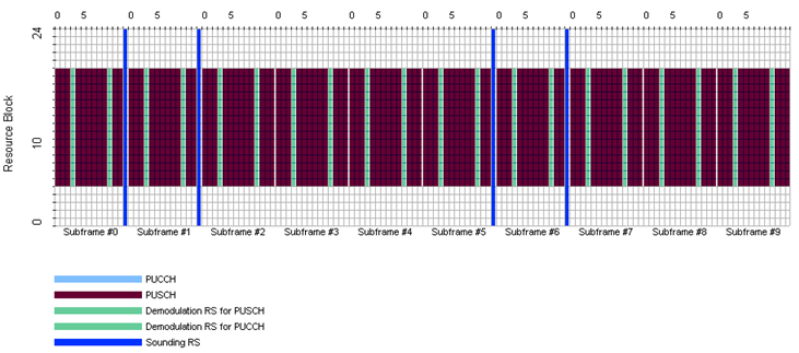
The diagram above shows the result of srs-SubframeConfig 7 in the frame. SRS appears in the last symbol of subframes 0, 1, 5 and 6, which are the subframes marked ON in the table above. The other subframes carry no SRS from any UE.
For srs-ConfigIndex, please refer to the following table from 36.213.
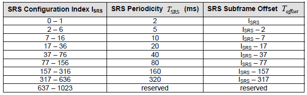
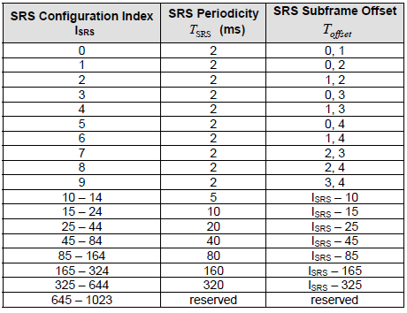
Both tables are unchanged in 36.213 v19.4.0. Note the difference between the FDD and TDD tables. FDD allows one SRS every 2 ms at the most, with srs-ConfigIndex 0 or 1. TDD uses srs-ConfigIndex 0 to 9 for a 2 ms period with two SRS positions in each 5 ms half frame, and those positions include UpPTS.
For the following parameters, refer to 36.211 5.5.3.2 Mapping to physical resources.
- srs-Bandwidth
- srs-HoppingBandwidth
- freqDomainPosition
One thing to notice that there is no flag for "srs-Hopping ON or OFF", but according to the specification (if I understood it correctly) we can figure "srs-Hopping ON or OFF" indirectly by combining the following two parameters.
srs-HoppingBandwidth >= srs-Bandwidth : SRS Hopping OFF
srs-HoppingBandwidth < srs-Bandwidth : SRS Hopping ON
Two captures, two levels : SIB2 carries soundingRS-UL-ConfigCommon, and RRC Connection Setup or Reconfiguration carries soundingRS-UL-ConfigDedicated.C_SRS and B_SRS set the width : srs-BandwidthConfig and srs-Bandwidth select mSRS,b in Tables 5.5.3.2-1 to 5.5.3.2-4.The Release 8 IEs are unchanged : later features were added as separate IEs such as srs-AntennaPort-r10.
SRS Signal Generation
You can skip following part if you are not realy, realy interested and it would be almost impossible to understand all of details unless you are implementing (programing) this process and test it. To be honest, I haven't tried program this part on my own, so I may not understand the details to the very bottom line. But I reorganized 36.211, 36.213 according to my own thought process and try to understand at least which parameters are involved in the process and how the RRC message parameter get involved in this low layer sequence generation.
SRS is also a kind of Zadoff Chu sequence. So the first step is to create a proper sequence for SRS and this process is pretty simple as follows.

Next step is to allocate the sequence data into each of resource elements which is reserved for carrying SRS. This process is real tricky one and most of SRS parameters are involved in this resource element mapping process. (enjoy !!! -:)
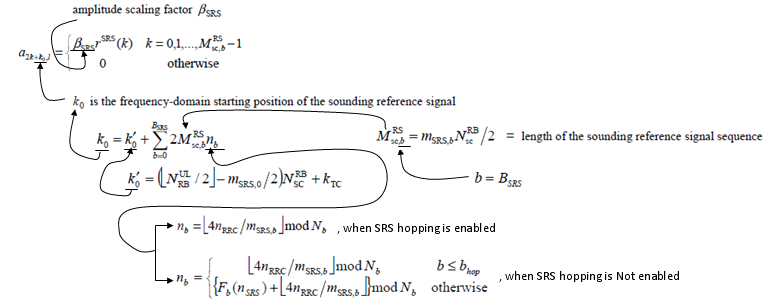
Check the two labels at the bottom of the diagram above against 36.211 clause 5.5.3.2. The labels are swapped. When SRS hopping is not enabled, that is bhop >= BSRS, nb = floor(4nRRC/mSRS,b) mod Nb and stays constant. When SRS hopping is enabled, that is bhop < BSRS, the piecewise formula with Fb(nSRS) applies. This matches the hopping rule given in the Rrc Parameters section.
If you read through the 36.211, you would notice that many of these parameters are coming from higher layer. Following is the higher layer message and I associated each of the information elements to the parameters you saw in previous process.
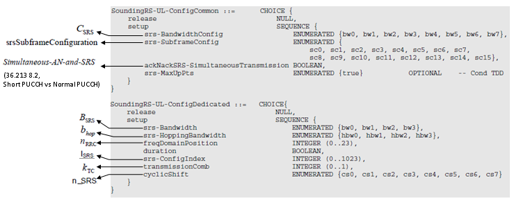
The diagram above ties each RRC field to its symbol in 36.211 and 36.213. In the common IE, srs-BandwidthConfig is CSRS, srs-SubframeConfig is the SRS subframe configuration, and ackNackSRS-SimultaneousTransmission is Simultaneous-AN-and-SRS. In the dedicated IE, srs-Bandwidth is BSRS, srs-HoppingBandwidth is bhop, freqDomainPosition is nRRC, srs-ConfigIndex is ISRS, transmissionComb is kTC and cyclicShift is nSRScs.
Unfortunately most of parameters related in SRS creation/resource allocation is hard to visualize, but there are at least a couple of parameters that can be visualized as follows.
< Uplink Frame Structure with SRS - Example on srs-subframeConfig >

The sequence is a cyclically shifted base sequence : cyclicShift sets the phase rotation alpha = 2 pi nSRScs/8.The RE mapping carries most parameters : k0 depends on kTC, mSRS,b and nb.Hopping changes nb over time : only when bhop < BSRS.
SRS and Short/Normal PUSCH
Once Common SRS and Dedicated SRS are configured, UE has to determine whether it transmit Normal PUSCH or Shortened PUSCH everytime it try to send PUSCH. Following example would help you understand the decision making criteria.
< Uplink Frame Structure with Normal and Short PUSCH >
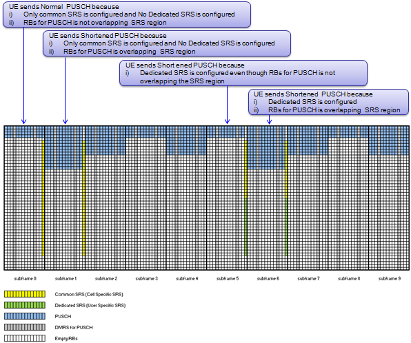
The diagram above shows four cases. In subframe 0, only common SRS is configured and the PUSCH RBs do not overlap the SRS region, so the UE sends normal PUSCH. In subframe 1, only common SRS is configured but the PUSCH RBs overlap the SRS region, so the UE sends shortened PUSCH. In subframe 5, the UE has dedicated SRS, so it sends shortened PUSCH even though the PUSCH RBs do not overlap the SRS region. In subframe 6, the UE has dedicated SRS and the RBs overlap, so it sends shortened PUSCH.
36.211 clause 5.3.4 gives the rule behind these cases. PUSCH is not mapped to the last SC-FDMA symbol of a subframe when the UE transmits SRS in the same subframe of the same serving cell. PUSCH is also not mapped there in a cell-specific SRS subframe when the PUSCH partly or fully overlaps the cell-specific SRS bandwidth. PUCCH has a similar rule. With ackNackSRS-SimultaneousTransmission TRUE, the UE uses the shortened PUCCH format in the cell-specific SRS subframes. With FALSE, the UE does not transmit SRS when it coincides with a PUCCH carrying HARQ-ACK or a positive SR.
Own SRS always shortens PUSCH : the UE never maps PUSCH to the symbol where it sends SRS.Other UEs' SRS shortens PUSCH only on overlap : the cell-specific SRS bandwidth decides.ackNackSRS-SimultaneousTransmission decides the PUCCH case : TRUE gives shortened PUCCH, and FALSE drops the SRS.
Example 01
A real log is the best check of the rules above. The example below takes the SRS configuration from SIB2 and RRC setup, works out what the rules predict, and compares that with the SRS the eNB actually received.
This example is from the test and trace log with Amari Callbox from Amarisoft.
DL NRB : 100, UL NRB : 100
SIB 2 :
Amarisoft Callbox log,
soundingRS-UL-ConfigCommon setup: {
  srs-BandwidthConfig bw2,
  srs-SubframeConfig sc3,
  ackNackSRS-SimultaneousTransmission TRUE
}
RrcSetup :
Amarisoft Callbox log,
soundingRS-UL-ConfigDedicated setup: {
  srs-Bandwidth bw3,
  srs-HoppingBandwidth hbw0,
  freqDomainPosition 0,
  duration TRUE,
  srs-ConfigIndex 37,
  transmissionComb 0,
  cyclicShift cs2
},
According the Rrc Configuration above, following configurations are applied.
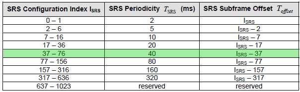
<36.213-Table 8.2-1:UE Specific SRS Periodicity T_SRS and Subframe Offset Configuration T_offset for trigger type 0, FDD>
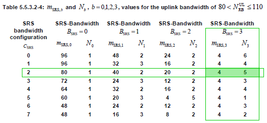
Let's read the two highlighted rows. The uplink has 100 RBs, so Table 5.5.3.2-4 applies. The value bw2 of srs-BandwidthConfig selects the row CSRS = 2, where mSRS,0 = 80. So the whole SRS bandwidth is 80 RBs. The value bw3 of srs-Bandwidth selects mSRS,3 = 4, so each SRS covers 4 RBs. Hopping is on, because srs-HoppingBandwidth hbw0 is smaller than bw3. The number of positions is N1 x N2 x N3 = 2 x 2 x 5 = 20, and 20 x 4 RBs = 80 RBs.
srs-ConfigIndex 37 falls in the row 37 to 76 of Table 8.2-1, so TSRS = 40 ms and Toffset = 37 - 37 = 0. The UE sends SRS in subframe 0 of every fourth radio frame. In SIB2, srs-SubframeConfig sc3 gives TSFC = 5 and offset {0} in Table 5.5.3.3-1, so subframe 0 is a cell-specific SRS subframe, as it must be. Finally, duration TRUE makes the SRS periodic until it is released.
As you see below, with this configuration SRS is being transmitted across 4 RBs every 4 radio frames and transmit 20 consecutive SRS to cover the whole bandwidth. In this example, you would notice that the pattern between SFN 56.0 and 132.0 repeats.
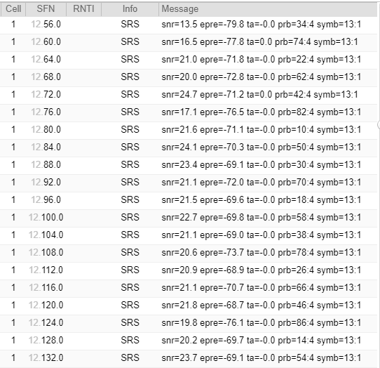
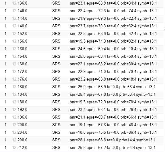
The log confirms each prediction. Every entry is at subframe 0, with SFN 56, 60, 64 and so on, so the period is 4 frames. Every entry is symb=13, the last symbol of the subframe. Each entry has prb=x:4, so each SRS covers 4 RBs. The start RB takes 20 values from 10 to 86. So the 80 RB SRS bandwidth starts at RB 10 and is centred in the 100 RB uplink. After 20 transmissions, the pattern starts again at prb=34 in SFN 136.
Bandwidth from two fields : bw2 and bw3 on a 100 RB uplink give 4 RB SRS inside an 80 RB SRS bandwidth.Period from one field : srs-ConfigIndex 37 gives 40 ms with offset 0.Hopping visits 20 positions : the whole SRS bandwidth is sounded once every 20 x 40 ms = 800 ms.
Reference
For further details, refer to the following references.
- 36.331, SoundingRS-UL-Config
- 36.211 5.5.3 Sounding reference signal
- 36.213 8.2 UE sounding procedure
[1] 3GPP TS 36.211 v19.3.0 - clause 5.5.3 Sounding reference signal, clause 5.3.4 Mapping to physical resources
[2] 3GPP TS 36.213 v19.4.0 - clause 8.2 UE sounding procedure, Tables 8.2-1 and 8.2-2
[3] 3GPP TS 36.331 v19.3.0 - SoundingRS-UL-Config and its field descriptions