In TD-SCDMA HSUPA, the Node B grants uplink resources to a scheduled UE on the E-AGCH, the E-DCH Absolute Grant Channel. This grant carries much more than a WCDMA absolute grant. A WCDMA grant holds only a power ratio and a scope bit. A TD-SCDMA grant also names the timeslots and the OVSF code that the UE may use. Let's go through the fields first. Then we'll see how the UE reads each field, and how the Node B codes and sends the message. The message flow around the grant is on the Scheduled vs Non Scheduled page.
- What does an E-AGCH carry in TD-SCDMA ?
- How does the UE read each field ?
- How is the E-AGCH coded and sent ?
- Reference
What does an E-AGCH carry in TD-SCDMA ?
A scheduled UE learns everything about its next E-PUCH transmission from one E-AGCH message. So the message has to fit power, code, time and feedback information into a few bits. The number of bits depends on the chip rate option.
The diagram below lays out the E-AGCH fields for the three TDD options. Each row is one option, and each block is one field with its length in bits. The labels at the top name the fields of the 1.28 Mcps row, with the bit notation of 25.222. The 3.84 Mcps and 7.68 Mcps rows are there for comparison.
E-AGCH Type 1 (based on 25.222 4.10 Coding for E-AGCH)
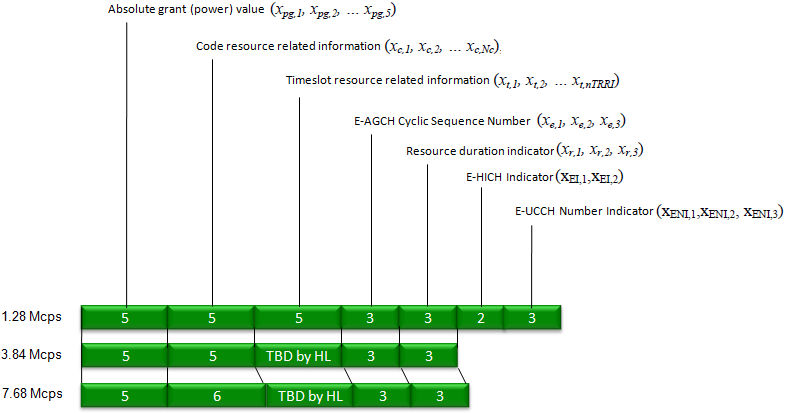
- Absolute grant (power) value, 5 bits : the maximum E-PUCH power that the UE may use.
- Code resource related information, 5 bits : the node of the OVSF code tree that the UE may use.
- Timeslot resource related information, 5 bits : a bitmap of the timeslots TS1 to TS5.
- E-AGCH Cyclic Sequence Number, 3 bits : a counter that helps the UE with outer loop power control of the E-AGCH.
- Resource duration indicator, 3 bits : the number of TTIs in the grant and their spacing. RRC decides per cell whether this field is present.
- E-HICH Indicator, 2 bits : the E-HICH that carries the Ack/Nack. This field exists in 1.28 Mcps only.
- E-UCCH Number Indicator, 3 bits : the number of E-UCCH instances, which is ENI + 1. This field exists in 1.28 Mcps only.
Add up the 1.28 Mcps row and you get 26 bits. Without the resource duration indicator, the message has 23 bits. That is why 25.222 gives the 1.28 Mcps length as 23 to 26 bits. The 3.84 Mcps and 7.68 Mcps rows have no E-HICH indicator and no E-UCCH number indicator. Their timeslot field is a bitmap whose length RRC configures, and the diagram marks it as TBD by HL. The 7.68 Mcps code field has 6 bits, because its OVSF tree goes down to SF 32.
The diagram shows E-AGCH type 1, which a 1.28 Mcps UE uses in normal operation. The UE changes to E-AGCH type 2 when semi-persistent E-PUCH scheduling is active, or when it is configured in MU-MIMO mode. Type 2 is a 30-bit format. It keeps the power, timeslot, ECSN and ENI fields, shortens the code field to 4 bits, and adds a field flag and two special information fields. Type 2 also carries E-AGCH orders, such as the order to release the semi-persistent E-PUCH resources.
One E-AGCH message is a complete resource grant : It gives the power, the code, the timeslots and the E-HICH for the E-PUCH.The 1.28 Mcps E-AGCH has 23 or 26 bits : The difference is the optional 3-bit resource duration indicator.Two fields exist only in 1.28 Mcps : The E-HICH indicator and the E-UCCH number indicator have no counterpart in 3.84 Mcps or 7.68 Mcps.
How does the UE read each field ?
The field lengths alone do not tell the UE what to do. Each field has a mapping table or a rule in 25.222 and 25.321. A few of these rules differ from what a WCDMA engineer would expect, so let's take the fields one at a time.
The absolute grant value is an index from 0 to 31. For 1.28 Mcps TDD, Table 26A of 25.222 maps index 0 to -12 dB and index 31 to 19 dB, in steps of 1 dB. The 3.84 Mcps and 7.68 Mcps options use Table 26 instead, which runs from 0 dB to 31 dB. The value is the maximum ratio of E-PUCH transmission power to reference power per TDD resource unit. A resource unit is one sixteenth of the OVSF code space in one timeslot. The UE combines this ratio with its current E-PUCH power to find the E-TFCs that it can use.
The code field is the number of a node on the OVSF code tree. Node 0 is C1(1), the single SF 1 code. Nodes 1 and 2 are the two SF 2 codes, and nodes 3 to 6 are the SF 4 codes. Nodes 7 to 14 are the SF 8 codes, and nodes 15 to 30 are the SF 16 codes. So one 5-bit value gives both the spreading factor and the code number. The UE then uses that spreading factor for all its E-PUCHs in the TTI.
The timeslot field is a bitmap for TS1 to TS5, and its first bit stands for TS1. A bit set to 1 means that the UE sends an E-PUCH in that timeslot. The same code applies in every granted timeslot, unless RRC configures non-rectangular resource allocation.
The resource duration indicator tells the UE how many TTIs the grant covers and how far apart they are. The table below gives the mapping from 25.321. When the cell does not configure the field, the UE assumes the value 0, which is a single TTI.
Resource Duration Indicator |
TTIs allocated |
TTI spacing |
0 |
1 |
1 |
1 |
2 |
1 |
2 |
2 |
2 |
3 |
2 |
4 |
4 |
4 |
1 |
5 |
4 |
2 |
6 |
4 |
4 |
7 |
8 |
1 |
The last three fields are short. The ECSN is a 3-bit counter for the outer loop power control of the E-AGCH, like the HCSN on the HS-SCCH. The E-HICH indicator picks one of up to four E-HICHs that RRC configures for the scheduled transmission of the UE. That E-HICH carries the Ack/Nack in the following schedule period. The E-UCCH number indicator gives ENI + 1 E-UCCH instances, so the range is 1 to 8. The UE repeats the E-UCCH and its TPC that many times in the TTI, spread evenly over the E-PUCH timeslots.
The power index is offset in 1.28 Mcps : Index 12 is 0 dB, so the range runs from -12 dB to 19 dB.One code field sets both SF and code : The node number 0 to 30 identifies one point on the OVSF code tree.Without an RDI, a grant lasts one TTI : The UE assumes RDI 0 when the cell does not configure the field.
How is the E-AGCH coded and sent ?
The E-AGCH is a shared channel, and many UEs listen to the same physical channels. So each message has to say which UE it is for, and it has to survive a weak downlink. The coding chain solves both problems with a masked CRC and a strong convolutional code.
The Node B first multiplexes the fields into 23 or 26 bits, in the order that the diagram shows. It then computes a 16-bit CRC over these bits and masks the CRC with the 16-bit E-RNTI of the UE. A UE checks every E-AGCH in the set that RRC tells it to monitor. It accepts a message only when the CRC matches after it removes its own E-RNTI. So the E-RNTI never appears as a separate field.
Next, a rate 1/3 convolutional code encodes the bits, and rate matching fits the result to 172 bits. After interleaving, the Node B splits the 172 bits over two physical channels, E-AGCH1 and E-AGCH2. Both use SF 16 and a 144-chip midamble. E-AGCH1 uses timeslot format 5, which carries 84 data bits, 2 SS bits and 2 TPC bits. E-AGCH2 uses timeslot format 0, which carries 88 data bits. The two together give exactly 84 + 88 = 172 bits.
The TPC and SS bits on E-AGCH1 are there for the E-PUCH. They adjust its transmit power and its uplink timing. For scheduled transmission, the UE also takes TPC commands for the E-PUCH from the E-HICH.
The E-RNTI is hidden in the CRC : The UE finds its grant by checking the masked CRC, not by reading an address field.172 coded bits go over two physical channels : E-AGCH1 carries 84 data bits, and E-AGCH2 carries 88.The E-AGCH also drives E-PUCH power control : E-AGCH1 carries the TPC and SS commands for the E-PUCH.
Reference
- 3GPP TS 25.221 v19.0.0 : Physical channels and mapping of transport channels onto physical channels (TDD)
- 3GPP TS 25.222 v19.0.0 : Multiplexing and channel coding (TDD)
- 3GPP TS 25.224 v19.0.0 : Physical layer procedures (TDD)
- 3GPP TS 25.321 v19.0.0 : Medium Access Control (MAC) protocol specification