This page explains how a TD-SCDMA UE sets its uplink transmit power. TD-SCDMA is the 1.28 Mcps option of UTRA TDD, so the rules come from 25.224 subclause 5.1.1, and the open loop formulas come from 25.331 subclause 8.5.7. The UE starts every uplink channel with open loop power control, based on the path loss it measures on the P-CCPCH. For the dedicated and shared channels, the Node B then controls the power with closed loop TPC commands. Each diagram on this page shows which downlink channel carries the TPC command for one uplink channel. The values are checked against 25.224 v19.0.0, 25.221 v19.0.0 and 25.331 v19.0.1.
The topics on this page are listed below.
- Which uplink channels are power controlled, and by which loop ?
- How does the UE set its initial power by open loop ?
- How does the TPC on the DL-DPCH control the UL-DPCH ?
- How does the TPC on the HS-SCCH control the HS-SICH ?
- How do the E-AGCH and the E-HICH control the E-PUCH ?
- Reference
Which uplink channels are power controlled, and by which loop ?
Let's first sort the uplink channels by the loop that controls them. A channel without a downlink TPC source can only use open loop. And every closed loop starts from an open loop value, so the two loops are never fully separate.
The random access channels use open loop only. The UpPCH carries the SYNC_UL signature, and the PRACH carries the RACH message after the FPACH has answered. Neither channel has an associated downlink channel that could send TPC commands. So higher layers set their power by open loop, and the E-RUCCH, the random access channel of HSUPA, uses the same formula as the PRACH.
The dedicated and shared channels use both loops. The UE sets the first transmission by open loop. After that, it follows the TPC commands from the Node B. This applies to the UL DPCH, the PUSCH, the HS-SICH and the E-PUCH. The table below lists each channel with its open loop formula and the downlink channel that carries its TPC commands.
UL channel | Initial power by open loop | Closed loop TPC carried on |
UpPCH | LPCCPCH + PRXUpPCHdes + (i - 1) x Pwrramp | none, open loop only |
PRACH | LPCCPCH + PRXPRACHdes + (iUpPCH - 1) x Pwrramp | none, open loop only |
E-RUCCH | same formula as the PRACH | none, open loop only |
UL DPCH | PRXDPCHdes + LPCCPCH | TPC field of the associated DL CCTrCH, or PLCCH |
PUSCH | PRXPUSCHdes + LPCCPCH | TPC field of the associated DL CCTrCH, or PLCCH |
HS-SICH | PRXHS-SICH + LPCCPCH | HS-SCCH, or HS-PDSCH for semi-persistent resources |
E-PUCH | PRXdes_base + LPCCPCH + βe | E-AGCH for scheduled, E-HICH for non-scheduled transmission |
Two limits apply on top of every formula in the table. First, higher layers can set Maximum_Allowed_UL_TX_power below the power class of the UE. Second, the UE may need more power in one timeslot than that maximum allows. In that case, the UE scales all uplink channels in the timeslot down by the same number of dB, so the total equals the maximum.
25.224 Table 2 gives the speed of each loop. The closed loop runs at 0 to 200 cycles per second, which is at most one command per 5 ms sub-frame. The closed loop step is 1, 2 or 3 dB. The open loop reacts with a delay of about 200 microseconds to 3575 microseconds. Also, all codes of one CCTrCH in one timeslot use the same power when they have the same spreading factor.
Random access is open loop only : the UpPCH, the PRACH and the E-RUCCH have no downlink TPC source, so the UE sets their power from path loss and a desired RX level alone.Every closed loop starts from open loop : the first UL DPCH, PUSCH, HS-SICH or E-PUCH transmission uses an open loop value. The TPC commands only move the power from there.The TPC source differs per channel : the UL DPCH listens to the DL DPCH, the HS-SICH to the HS-SCCH, and the E-PUCH to the E-AGCH or the E-HICH. The three sections below cover them in that order.One timeslot shares one power limit : when the sum is too high, the UE scales all channels in that timeslot by the same dB value. So the ratio between them stays the same.
How does the UE set its initial power by open loop ?
Open loop power control answers one question. How strongly must the UE transmit, so that the Node B receives a wanted level? The UE cannot measure the uplink, so it measures the downlink path loss and assumes that the uplink loss is the same. This assumption fits TDD well, because both directions use the same carrier.
The path loss term is LPCCPCH. The UE takes the reference transmit power "Primary CCPCH Tx Power" and subtracts the P-CCPCH RSCP that it measures. The cell broadcasts "Primary CCPCH Tx Power" in System Information Block type 5 and type 6. The network can also signal it to one UE in the IE "Uplink DPCH Power Control Info". Every formula then adds a desired RX power, which is the level the Node B wants to see at its receiver.
The UpPCH formula adds a ramp. The UE sends a SYNC_UL signature, and waits for an FPACH answer. If no answer comes, the UE raises the power by Pwrramp, the IE "Power Ramp step", and tries again. The counter i runs from 1 to Max SYNC_UL Transmissions. PRXUpPCHdes and the ramp step come in the IE "SYNC_UL info" in System Information Block type 5 and type 6. The RRC ASN.1 codes PRXUpPCHdes as INTEGER (0..62) with the actual value = IE value - 120, so the range is -120 dBm to -58 dBm.
The PRACH formula keeps the ramp that worked. The term iUpPCH is the final value of i, so the PRACH starts from the power level of the successful SYNC_UL attempt. PRXPRACHdes does not come from system information. The Node B sends it in the FPACH response to the successful SYNC_UL.
Let's put numbers into the two formulas. Assume that the cell broadcasts a Primary CCPCH Tx Power of 30 dBm and that the UE measures an RSCP of -75 dBm. Then LPCCPCH is 105 dB. With PRXUpPCHdes = -100 dBm, the UE sends the first SYNC_UL at 105 - 100 = 5 dBm. With a ramp step of 2 dB, the UE sends the third attempt at 9 dBm. If the FPACH answers the third attempt with PRXPRACHdes = -95 dBm, the UE sends the PRACH at 105 - 95 + 2 x 2 = 14 dBm.
The dedicated channels use the same idea without a ramp. The network sends PRXDPCHdes in the IE "Uplink DPCH Info" and the IE "Uplink DPCH Power Control Info". PRXHS-SICH is sent in the IE "Downlink HS-PDSCH Information". PRXdes_base for the E-PUCH is sent in the IE "E-PUCH Info" in CELL_DCH, or in System Information Block type 5 for enhanced CELL_FACH and Idle mode. As soon as the UE receives TPC bits for the uplink DPCH, it moves to closed loop power control.
Open loop can also return during a call. Suppose that no uplink data was sent between two TPC commands. The UE then ignores the resulting command. For the next transmission in that timeslot and CCTrCH, the UE either reuses the previous power level, with an optional path loss correction, or runs the open loop again. For a short pause, 25.224 says the UE should reuse the previous level.
Open loop needs two broadcast values and one measurement : the UE needs the Primary CCPCH Tx Power and the desired RX power from the network, and it measures the P-CCPCH RSCP itself.The PRACH inherits the UpPCH ramp : the (iUpPCH - 1) x Pwrramp term carries the extra power of the successful SYNC_UL into the RACH message.PRXPRACHdes is not broadcast : the FPACH answer delivers it to the one UE whose signature was detected.Open loop error becomes the starting error of the closed loop : if the RSCP measurement is off, the first DPCH transmission is off by the same amount. The TPC commands then correct it at 1 to 3 dB per step.
How does the TPC on the DL-DPCH control the UL-DPCH ?
The UL DPCH is the basic case, and the other two diagrams on this page follow its pattern. After the first open loop transmission, the Node B compares the received quality with a target. It then tells the UE to go up or down in every sub-frame.
Figure 1 draws this loop with two bursts. The DL-DPCH on the left carries a short TPC field, drawn as a dark band. A green arrow labelled "Controls" runs from that field to the UL-DPCH on the right.
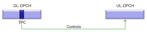
Figure 1. UL-DPCH closed loop power control. A TPC field inside the downlink DPCH burst sets the power of the uplink DPCH.
The TPC field sits right after the SS symbols : in 1.28 Mcps TDD, the SS symbols follow the midamble, and the TPC symbols follow the SS symbols. Higher layers configure each timeslot with one TPC symbol, no TPC symbol, or 16/SF TPC symbols. A UE gets TPC information at least once per 5 ms sub-frame.One command controls one timeslot and CCTrCH pair : a TPC command controls all UL DPCHs and PUSCHs of one uplink CCTrCH in one timeslot. 25.221 subclause 5A.2.2.2 numbers the TPC symbols and the uplink pairs, and it maps them to each other.The coding depends on the modulation : with QPSK, bit 0 means 'Down' and bit 1 means 'Up'. With 8PSK, 000 means 'Down' and 110 means 'Up'.The UE moves one step per command : 'Up' raises the power by one step and 'Down' lowers it by one step. The step is 1, 2 or 3 dB. If higher layers allow it, the UE may also correct the power with the path loss that it estimates on the beacon channels.The Node B decides by quality : in the SIR based example of 25.224, the Node B sends 'Down' when the measured SIR is higher than SIRtarget. It sends 'Up' when the measured SIR is lower than or equal to the target. An outer loop moves SIRtarget to meet the quality target from higher layers.
Figure 1 shows the usual source of the command, but not the only one. UTRAN can move the TPC commands for an uplink CCTrCH onto the PLCCH, a common channel that carries only TPC and SS for several UEs. This is useful for HS-DSCH operation without an associated downlink DPCH. Out of sync handling then follows the PLCCH. If the PLCCH quality over the last 160 ms is worse than Qout, the UE stops that uplink CCTrCH. It restarts when the quality over 160 ms is better than Qin.
TD-SCDMA sends TPC and SS side by side : the same burst area carries the power command and the uplink sync command. So one downlink burst closes two loops at once.The TPC mapping is per timeslot : a UE with two uplink timeslots needs two TPC commands. 25.221 decides which downlink TPC symbol belongs to which uplink timeslot.PLCCH replaces the DL DPCH as TPC source : when there is no downlink DPCH, the PLCCH still keeps the uplink closed loop running.
How does the TPC on the HS-SCCH control the HS-SICH ?
The HS-SICH is the uplink feedback channel of HSDPA. It carries the ACK or NACK and the channel quality report, and it only exists when the Node B has just scheduled the UE. So the HS-SICH cannot rely on a downlink DPCH for its TPC commands. TD-SCDMA puts the command on the HS-SCCH instead, which is the channel that triggers each HS-SICH.
Figure 2 has the same shape as Figure 1. The HS-SCCH on the left carries the TPC field as a dark band. The green "Controls" arrow runs from that field to the HS-SICH on the right.
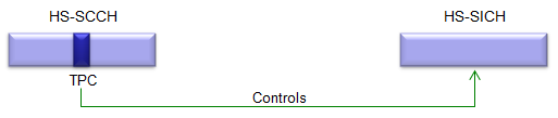
Figure 2. HS-SICH closed loop power control. The HS-SCCH that schedules the UE also sets the power of the HS-SICH that answers it.
The HS-SCCH carries TPC and SS, but no TFCI : 25.221 assigns it time slot format #5 for HS-SCCH1 and #0 for HS-SCCH2. The HS-SICH itself also carries TPC and SS, and it has no TFCI.The first HS-SICH uses open loop : after the first detected HS-SCCH, the UE sets the HS-SICH power from PRXHS-SICH + LPCCPCH.Short gaps keep the closed loop : when HS-SICHs in the same timeslot come closer together than a threshold from higher layers, the UE keeps applying TPC commands from the last instance. When the gap is equal to or larger than the threshold, the UE starts again from open loop.An ACK gets extra power : when the HS-SICH carries an ACK, the UE adds a power offset from higher layers to the whole HS-SICH. 25.331 calls it the Ack-Nack Power Offset, and the network sends it in the IE "HS-SCCH Info".
Two cases change the source of the command. The first is semi-persistent HS-PDSCH resources, which are used without an HS-SCCH. The HS-PDSCH then carries the TPC command for the HS-SICH. When both channels deliver a command in the same sub-frame, the UE uses it once if both are identical and discards both if they differ. The second case is an HS-SCCH order for uplink synchronization establishment. The UE ignores the TPC command on that order.
The HS-SICH loop is not continuous : it runs only while scheduling is frequent, and it restarts from open loop after a long pause.ACK and NACK can arrive at different levels : 25.331 defines the offset as the difference in desired RX power between an HS-SICH with an ACK and one with a NACK. So the network can protect the ACK more than the NACK.MIMO adds a delta : for dual stream transmission with two ACKs, the UE applies a power offset from higher layers. The open loop value also gets a delta for the number of streams.
How do the E-AGCH and the E-HICH control the E-PUCH ?
HSUPA in TD-SCDMA sends data on the E-PUCH, and an E-PUCH transmission can be scheduled or non-scheduled. The two modes use different downlink control channels. So the TPC command for the E-PUCH comes from a different channel in each mode.
Figure 3 draws the two modes on two rows. In the upper row, labelled "In Scheduled Mode", the TPC field of the E-AGCH controls the E-PUCH. In the lower row, labelled "In Non-Scheduled Mode", the TPC field of the E-HICH controls the E-PUCH.
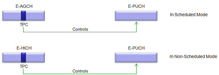
Figure 3. E-PUCH closed loop power control. The E-AGCH carries the TPC command for scheduled transmission, and the E-HICH carries it for non-scheduled transmission.
The E-AGCH has a real TPC field : it carries the absolute grant, plus a TPC field and an SS field for the E-PUCH. It uses time slot format #5 or #0 and carries no TFCI.The E-HICH signals TPC by sequence choice : each non-scheduled UE gets a group of 4 signature sequences. The first one indicates ACK or NACK. The other three and their inverted forms give six states, and 25.221 Table 8KE maps each state to a TPC and SS command pair. So the dark band in the E-HICH row is a drawing convention, not a separate field.The drawing separates what the UE combines : for non-scheduled transmission, the TPC comes only on the E-HICH. But the UE keeps one closed loop quantity for both modes, and commands from both channels update it.
That closed loop quantity is Pe-base. It starts at PRXdes_base, the reference desired E-PUCH RX power. On each TPC 'Up' the UE adds Δe-base, and on each 'Down' it subtracts Δe-base. Higher layers configure this step size. The E-PUCH power in each timeslot is then:
PE-PUCH = Pe-base + L + βe
L is the path loss term, and βe is the gain factor. The equation images are missing from the cached text of 25.224, so this line is written from the terms that 25.224 subclause 5.1.1.6 lists. It matches the open loop formula of 25.331, where PRXdes_base takes the place of Pe-base.
The gain factor is what makes the E-PUCH different from the DPCH. βe depends on the selected E-TFC transport block size, the E-PUCH resources, the modulation and the HARQ power offset. It also has a part that depends on the spreading factor, from 25.224 Table 2a. This part is 12 dB at SF 1, 9 dB at SF 2, 6 dB at SF 4, 3 dB at SF 8 and 0 dB at SF 16. So a larger block in fewer resources gets more power. The UE's higher layers use the resulting E-PUCH power together with the absolute grant to decide which E-TFCs are available.
Two TPC sources, one power state : when the E-AGCH and the E-HICH deliver commands in the same sub-frame, the UE uses one command if they are identical and discards both if they differ.A long pause resets the loop : after an extended pause in TPC reception, signalled by higher layers, the UE sets Pe-base back to PRXdes_base.Each carrier has its own loop : with multi-carrier E-DCH, the open loop and the closed loop of the E-PUCH run independently on each carrier.The closed loop also affects the data rate : the UE's higher layers use the calculated E-PUCH power together with the absolute grant to decide the set of available E-TFCs. So a change in Pe-base can change which block sizes the UE may select.
Reference
- 25.224 Physical layer procedures TDD - v19.0.0, subclause 5.1.1 Uplink control, Table 2, Table 2a and Annex A
- 25.221 Physical channels and mapping of transport channels onto physical channels TDD - v19.0.0, subclauses 5A.2.2.2 Transmission of TPC, 5A.3.13 PLCCH and Table 8KE
- 25.331 Radio Resource Control RRC protocol specification - v19.0.1, subclause 8.5.7 Open loop power control