In TD-SCDMA, timing advance means uplink synchronization. The Node B wants the bursts of all UEs in one uplink timeslot to arrive at the same moment. So each UE must transmit early, by its own round trip delay. This page follows the UE from its first SYNC-UL in the UpPTS to the SS commands that keep it aligned in connected mode. The diagram on this page shows how the Node B measures the arrival of the UpPTS against its reference timing. The rules come from 25.224 subclause 5.2 and 25.221 subclause 5A.3.3, and the values are checked against v19.0.0 of both specifications.
The topics on this page are listed below.
- Why does a TD-SCDMA UE have to advance its uplink timing ?
- How does the Node B measure the arrival of the UpPTS ?
- How does the UE apply the correction and keep its timing ?
- Reference
Why does a TD-SCDMA UE have to advance its uplink timing ?
Let's start with the reason the Node B cares about uplink timing at all. In TD-SCDMA, several UEs share one uplink timeslot, and only their codes and midambles separate them. The Node B detects them jointly, and that works best when all their bursts arrive at the same time.
Each UE takes its downlink timing from the DwPTS it receives. That timing is already late by the one way propagation delay. If the UE sent its uplink burst on this received timing, the burst would reach the Node B late by the whole round trip delay. A UE at the cell edge would then arrive later than a UE next to the Node B. So each UE sends its uplink early, by an amount that cancels its own round trip delay.
The UE cannot know this delay before its first uplink transmission. It can receive the downlink, but its distance to the Node B is still uncertain. For this reason, the first uplink transmission goes into a special slot, the UpPTS, and not into a traffic timeslot. The main GP of 96 chips sits between the DwPTS and the UpPTS. It gives room for a SYNC-UL that arrives early. The 96 chips last 75 microseconds at 1.28 Mcps, and light travels about 22.5 km in that time. So the GP can absorb a round trip of about 11 km.
The work is then split into two stages. The establishment stage runs during random access, and it uses the UpPCH, the FPACH and the PRACH or the E-RUCCH. The maintenance stage runs in connected mode, and it uses SS commands in every sub-frame. The next two sections follow these stages in order.
Timing advance serves joint detection : the Node B wants all bursts of one uplink timeslot to arrive together, so each UE cancels its own round trip delay.The first uplink transmission is an estimate : before the SYNC-UL, the UE knows only its received downlink timing. It estimates the propagation delay from the path loss.The GP absorbs the error of the estimate : the 96 chip gap before the UpPTS lets an early SYNC-UL arrive without overlapping the DwPTS.1.28 Mcps TDD uses the FPACH and SS commands : 25.224 describes timing advance in steps of 4 chips, sent by higher layer messages, for the 3.84 Mcps and 7.68 Mcps options. The 1.28 Mcps option corrects the timing on layer 1 instead.
How does the Node B measure the arrival of the UpPTS ?
The Node B answers every detected SYNC-UL with one timing value, the received starting position of the UpPCH. Before we read that value, we need the reference point it is measured from. Figure 1 puts the reference and three example arrivals on one time axis.
First, the UE decides when to send the SYNC-UL. 25.224 subclause 5.2.2 gives the start time as TTX-UpPCH = TRX-DwPCH - 2tp + 12 x 16 TC + nUpPCHShift x 16 TC. TRX-DwPCH is the start of the DwPCH as the UE receives it. The term 12 x 16 TC is 192 chips, which is the DwPTS plus the GP. So without the advance, the UE would start the SYNC-UL where the UpPTS begins on its own received timing. The UE estimates the propagation delay tp from the received P-CCPCH or DwPCH power, and the default advance 2tp is 48 chips. Higher layers can also move the UpPCH with nUpPCHShift, from 0 to 127 steps of 16 chips.
The diagram below shows the special timeslots of one sub-frame, as the Node B sees them. The DwPTS is 96 chips or 75 microseconds long, and holds a GP of 32 chips and the SYNC-DL of 64 chips. The main GP of 96 chips follows. The UpPTS is 160 chips or 125 microseconds long, and holds the SYNC-UL of 128 chips and a GP of 32 chips. A red arrow marks the start of the SYNC-UL as the expected timing for the UL PTS, which the diagram calls the Reference Timing. Under the time axis, three hatched boxes show a SYNC-UL that arrives early, on time and late.
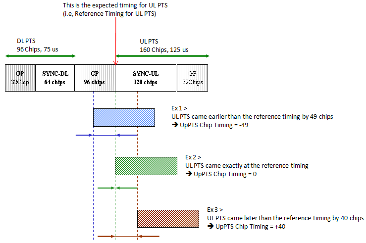
Figure 1. UpPTS arrival timing at the Node B. The Node B measures where the received SYNC-UL starts relative to the reference timing, and the sign shows whether the UE was early or late.
Ex 1 arrives 49 chips early : the blue box starts inside the main GP, 49 chips before the reference. The diagram records this as UpPTS Chip Timing = -49.Ex 2 arrives on time : the green box starts exactly at the reference timing, so UpPTS Chip Timing = 0.Ex 3 arrives 40 chips late : the brown box starts 40 chips after the reference, so UpPTS Chip Timing = +40.The arrows mark the gap : under each box, a pair of arrows spans the distance between the actual start and the reference. This distance is what the UE must correct in its next uplink transmission.
The value sent to the UE is not this signed number. 25.224 subclause 5.6.3.1.3 defines UpPCHPOS = UpPCHRxpath - UpPCHTS. UpPCHRxpath is the time at which the Node B receives the SYNC-UL. UpPCHTS is a point 128 chips before the start of the UpPCH on the internal timing of the Node B. So an on-time SYNC-UL gives 128 chips, and a SYNC-UL that is early by up to 128 chips still gives a value of zero or more.
The FPACH carries UpPCHPOS as a 13 bit number from 0 to 8191, in units of 1/8 chip. 25.221 Table 8J puts the 11 least significant bits in the UpPCHPOS field and the 2 most significant bits in the extended part field. Let's convert the three examples. Ex 1 gives 128 - 49 = 79 chips, which the FPACH carries as 632. Ex 2 gives 128 chips, or 1024. Ex 3 gives 168 chips, or 1344.
UpPCHPOS is an offset, not a signed error : subtract 128 chips from it to get the signed value that Figure 1 calls UpPTS Chip Timing.The resolution is 1/8 chip : Figure 1 uses whole chips, but the FPACH value can report the position in 1/8 chip steps.The answer comes within 4 sub-frames : the FPACH also carries the Signature Reference Number, the Relative Sub-Frame Number and the transmit power level command for the RACH message. So one burst corrects both the timing and the power.
How does the UE apply the correction and keep its timing ?
A measured error helps only when the UE applies it to the next burst. Here the timing control changes from a one-time correction during random access to a loop that runs for the whole connection.
The PRACH or the E-RUCCH is the first burst that uses the correction. 25.224 subclause 5.2.3 gives its start time as TTX-PRACH = TRX-PRACH - (UpPCHADV + UpPCHPOS - 8 x 16 TC). TRX-PRACH is the time at which the PRACH would start on the received downlink timing. UpPCHADV is the advance that the UE used for the SYNC-UL. The term 8 x 16 TC is 128 chips, and it removes the offset inside UpPCHPOS. The E-RUCCH uses the same formula.
Let's apply the formula to the three examples. Ex 2 arrived on time, so the bracket equals UpPCHADV, and the UE keeps the same advance. Ex 1 arrived 49 chips early, so the bracket is UpPCHADV - 49 chips. The UE therefore starts the PRACH 49 chips later than with the old advance. Ex 3 arrived 40 chips late, so the UE advances the PRACH by 40 more chips. In each case, the correction has the opposite sign of the UpPTS Chip Timing in Figure 1.
After the PRACH, the uplink synchronization is established, and a closed loop takes over. The Node B measures the timing of each UE from the midamble of its uplink burst. Every UE in a timeslot uses a different midamble, so the Node B can separate their channel impulse responses and read each arrival time. The Node B then sends SS commands in the next available downlink timeslot. In the traffic burst, the SS command sits directly after the midamble.
25.221 Table 8D gives the coding for QPSK. 00 means 'Down', 11 means 'Up' and 01 means 'Do nothing'. With 8PSK, Table 8E uses 000, 110 and 011. The UE combines the SS commands for one uplink timeslot over the last M sub-frames. Higher layers set this Uplink synchronisation frequency M from 1 to 8. A combined 'Up' advances the transmit timing by k/8 chip, and a combined 'Down' delays it by k/8 chip. Higher layers also set this Uplink synchronisation step size k from 1 to 8, so one step is between 1/8 chip and one chip.
The same loop covers the other uplink channels. The HS-SICH takes its first timing from the associated uplink DPCH or non-scheduled E-PUCH. After that, it follows SS commands on the HS-SCCH or the HS-PDSCH. The E-PUCH follows SS commands on the E-AGCH or the E-HICH. With multi-carrier E-DCH, all carriers of one UE use the same timing advance in a TTI.
Two events interrupt the loop. The first is a handover. In a 1.28 Mcps TDD to 1.28 Mcps TDD handover, and if higher layers indicate it, the UE starts in the new cell with TAnew = TAold + 2Δt. Here Δt is the relative timing difference between the new and the old cell. The second is a pause in CELL_FACH, where uplink synchronization does not need to be maintained. The Node B tracks each UE with the timer T-sync. When the timer expires, the Node B sends an HS-SCCH order, and the UE runs random access again with the UpPCH and the E-RUCCH.
The PRACH applies the FPACH correction once : the UE subtracts UpPCHPOS - 128 chips from its old advance. So an early SYNC-UL leads to a later PRACH, and a late SYNC-UL leads to an earlier PRACH.SS commands keep the timing in connected mode : the Node B measures the midamble and sends 'Up', 'Down' or 'Do nothing'. The UE moves by k/8 chip per combined command.M and k set the speed of the loop : a larger M combines more sub-frames before each step, and a larger k makes each step bigger.Loss of sync in CELL_FACH means a new random access : after T-sync expires, the HS-SCCH order sends the UE back to the SYNC-UL and the FPACH.
Reference
- 25.224 Physical layer procedures TDD - v19.0.0, subclauses 5.2 UL synchronisation, 5.3.3 and 5.6.3.1.3 Received starting position of the UpPCH
- 25.221 Physical channels and mapping of transport channels onto physical channels TDD - v19.0.0, subclauses 5A.1 Frame structure, 5A.2.2.3 Transmission of SS, 5A.3.3 FPACH and 5A.3.5 DwPCH and UpPCH