A WCDMA cell sends many downlink physical channels at the same time, on the same carrier, separated by channelisation codes. They all share one time grid: a 10 ms radio frame of 15 slots, each 2560 chips long. What differs is what each channel puts into a slot, and how far its frame is shifted from the P-CCPCH.
This page starts with the timing relationship among the channels, and then takes each downlink physical channel in turn. For each one it shows the frame or subframe structure from 25.211 and explains the fields. The figure and table numbers are those of 25.211 v19.0.0. Two of the tables have gained rows since the pictures were made, and the sections below list the new rows.
- Overall Timing relationship among physical channels
- SCH - Synchronization Channel
- CPICH - Common Pilot Channel
- P-CCPCH - Primary Common Control Physical Channel
- S-CCPCH - Secondary Common Control Physical Channel
- AICH - Acquisition Indicator Channel
- DPCH - Dedicated downlink physical channels
- HS-SCCH - HS Shared Control Channel
- HS-PDSCH - High Speed Physical Downlink Shared Channel
- Reference
Overall Timing relationship among physical channels
Why does a UE need a single timing reference? The UE must know where every frame starts, on every channel, before it can decode any of them. 25.211 clause 7.1 makes the P-CCPCH, which carries the cell SFN, the timing reference for all physical channels. The downlink channels use it directly, and the uplink channels use it indirectly through the downlink timing.
The diagram below stacks the downlink channels over two radio frames, with SFN modulo 2 = 0 and SFN modulo 2 = 1. Each row starts where 25.211 puts its frame, so the offsets appear as the arrows marked with a tau. The AICH row is divided into access slots instead of frames.
< 25.211 - Figure 29: Radio frame timing and access slot timing of downlink physical channels >
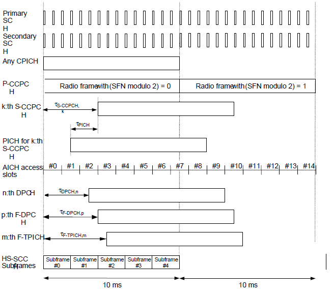
25.211 Figure 29. SCH, CPICH and P-CCPCH share one frame timing, and every other channel is placed relative to it.
Primary SCH, Secondary SCH, Any CPICH and P-CCPCH : identical frame timing. They define the reference.k:th S-CCPCH : offset tauS-CCPCH,k, a multiple of 256 chips from 0 to 149 steps. An S-CCPCH that carries BCH has offset 0.PICH for k:th S-CCPCH : starts tauPICH = 7680 chips, which is 3 slots, before the S-CCPCH that carries the matching paging message.AICH access slots : #0 to #14 over two frames, each access slot 5120 chips. Access slot #0 starts with the P-CCPCH frame of SFN modulo 2 = 0.n:th DPCH, p:th F-DPCH and m:th F-TPICH : each has its own offset, again a multiple of 256 chips from 0 to 149 steps.HS-SCCH subframes : #0 to #4 of 2 ms each. Subframe #0 starts with the P-CCPCH frame.
The offsets are all multiples of 256 chips, which is one symbol at SF 256. So the network can shift a channel by whole symbols without breaking the slot structure. For dedicated channels this spreads the frame boundaries of different UEs over time. The same property lets F-DPCH place the TPC commands of several UEs on one code.
One reference : the P-CCPCH frame and its SFN.256 chip steps : every configurable offset uses the same unit.Fixed relations : PICH before S-CCPCH, AICH aligned with even SFN, HS-SCCH aligned with every frame.
SCH - Synchronization Channel
The SCH answers the first question of cell search: where do the slots and frames of this cell start? It is also the only downlink channel that is not spread by the cell's scrambling code, because the UE does not know that code yet.
- The SCH consists of two sub channels,the Primary and Secondary SCH.
- The 10 ms radio frames of the Primary and Secondary SCH are divided into 15 slots,each of length 2560 chips
< 25.211 - Figure 18: Structure of Synchronisation Channel (SCH) >
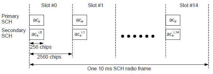
25.211 Figure 18. The PSC repeats in every slot, while the SSC changes from slot to slot and so marks the frame boundary.
Primary SCH : acp in every slot, 256 chips long at the start of the 2560 chip slot.Secondary SCH : acsi,k, where i is the scrambling code group and k is the slot number from 0 to 14.Bottom arrow : one 10 ms SCH radio frame.
< Primary SCH >
- Primary SCH has the length of 256 chips
- The PSC is the same for every cell in the system
< Secondary SCH >
- Made up of consists of repeatedly transmitting a length 15 sequence of modulated codes of length 256 chips
- Secondary Synchronisation Codes (SSC), transmitted in parallel with the Primary SCH.
25.211 adds the details that make cell search work. Each SSC is one of 16 codes of length 256, and the sequence of 15 SSCs over a frame identifies one of 64 scrambling code groups, i from 0 to 63. The symbol a on both codes tells the UE whether the P-CCPCH is STTD encoded: a = +1 means yes, and a = -1 means no. The network may also send the SCH with TSTD, switching between antenna 1 and antenna 2 in even and odd slots.
25.214 Annex C describes cell search in three steps. First, the UE correlates with the PSC, which is common to all cells, and finds the slot timing. Second, it correlates with all SSC sequences and finds both the frame timing and the code group. Third, it tries the 8 primary scrambling codes of that group on the CPICH, which is the subject of the next section.
PSC : slot timing, the same code in every cell.SSC sequence : frame timing and one of 64 code groups.Modulation symbol a : P-CCPCH STTD on or off.
CPICH - Common Pilot Channel
After the SCH, the UE knows the slot and frame timing and the code group. The CPICH answers the next question: which of the 8 primary scrambling codes in the group does this cell use? Later it also serves as the phase reference for most other downlink channels.
- Data Rate : a fixed rate (30 kbps = 20 bits/slot * 15 slots/frame * 100 frames/sec, SF=256)
- Contents : a pre-defined bit sequence.
- Two Types of CPICH : Primary CPICH(P-CPICH) and Secondary CPICH(S-CPICH)
< 25.211 - Figure 13: Frame structure for Common Pilot Channel >
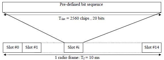
25.211 Figure 13. Every CPICH slot carries the same pre-defined sequence, so the UE can correlate against it without any other knowledge.
Slot : Tslot = 2560 chips and 20 bits, all of them the pre-defined bit sequence.Frame : Slot #0 to Slot #14 in Tf = 10 ms.
< P-CPICH(Primary CPICH) >
- The same channelization code is always used for the P-CPICH
- The P-CPICH is scrambled by the primary scrambling code(PSC).// UE detect PSC from P-CPICH
- There is one and only one P-CPICH per cell
- The P-CPICH is broadcast over the entire cell.
< S-CPICH(Secondary CPICH) >
- An arbitrary channelization code of SF=256 is used for the S-CPICH
- An S-CPICH is scrambled by either the primary or a secondary scrambling code
- There may be zero, one, or several S-CPICH per cell
- An S-CPICH may be transmitted over the entire cell or only over a part of the cell
- An S-CPICH that is intended to be used as phase reference for the second, third or fourth transmit antenna by UEs configured in MIMO mode or in MIMO mode with four transmit antennas shall be transmitted over the entire cell using the primary scrambling code and the antenna 1 pattern.
The P-CPICH has a fixed role, while the S-CPICH is a tool the network can configure. The P-CPICH always uses the same channelisation code, so the only unknown is the scrambling code, and that is exactly what cell search step 3 needs. The P-CPICH is also the default phase reference, and UE measurements such as CPICH RSCP and CPICH Ec/No are made on it. An S-CPICH is used when the P-CPICH is not suitable, for example as the reference for extra MIMO antennas or for a beam that covers only part of the cell.
P-CPICH : fixed code, primary scrambling code, one per cell.Cell search step 3 : the UE finds the primary scrambling code by correlating over the CPICH.S-CPICH : zero or more per cell, for MIMO antennas or partial coverage.
P-CCPCH - Primary Common Control Physical Channel
Once the UE knows the primary scrambling code, it can read the cell. The P-CCPCH carries the BCH, which holds the MIB and the SIBs. Its format is fixed, so the UE can decode it without any configuration.
- Data Rate : a fixed rate (30 kbps = 20 bits/slot * 15 slots/frame * 100 frames/sec, SF=256)
- Contents : BCH(MIB / SIB) Transport data.
- Not transmitted during the first 256 chips of each slot. Instead, Primary SCH and Secondary SCH are transmitted during this period
- no TPC commands, no TFCI and no pilot bits are transmitted within this channel
< 25.211 - Figure 15: Frame structure for Primary Common Control Physical Channel >
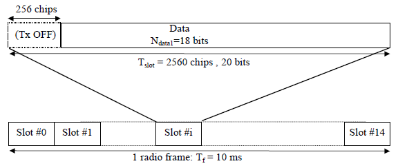
25.211 Figure 15. The first 256 chips of each slot are left to the SCH, so only 18 of the 20 bits carry BCH data.
Tx OFF : the first 256 chips of every slot, where the SCH is sent.Data : Ndata1 = 18 bits in the remaining part of the 2560 chip slot.Frame : Slot #0 to Slot #14 in Tf = 10 ms.
The two Tx OFF bits per slot reduce the rate. The channel runs at 30 kbps at SF 256, but only 18 of each 20 bits carry data, so the BCH gets 27 kbps. The P-CCPCH also has no pilot, TPC or TFCI, so the UE uses the P-CPICH as its phase reference. When the network uses STTD on the P-CCPCH, it tells the UE through the modulation of the SCH, and higher layers signal it as well.
Fixed format : SF 256, 18 data bits per slot.No control fields : no TPC, no TFCI, no pilot.Shares the slot with the SCH : Tx OFF in the first 256 chips.
S-CCPCH - Secondary Common Control Physical Channel
The P-CCPCH cannot carry paging or common data, because its rate and format are fixed. The S-CCPCH does that job. Its rate is configurable, and it carries the FACH and the PCH.
- Data Rate : a variable rate ( 20*(2^k) bits/slot * 15 slots/frame * 100 frames/sec, SF=256/(2^k)), where k=0..6
- Contents : FACH / PCH data.
< 25.211 - Figure 17: Frame structure for Secondary Common Control Physical Channel >
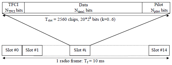
25.211 Figure 17. Unlike the P-CCPCH, the S-CCPCH has an optional TFCI and pilot field, and its slot size changes with the spreading factor.
TFCI : NTFCI bits at the start of the slot.Data : Ndata1 bits in the middle.Pilot : Npilot bits at the end of the slot.Slot size : 20 x 2k bits with k = 0 to 6, so SF goes from 256 down to 4.
25.211 Table 18 lists the slot formats of the S-CCPCH. Each row fixes the SF and how the bits of a slot are split between data, pilot and TFCI.
< 25.211 - Table 18: Secondary CCPCH fields >
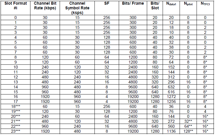
25.211 Table 18. Slot formats 0 to 17 pair each SF with and without pilot and TFCI, and slot formats 18 to 23 are for MBSFN.
Slot formats 0 to 17 : two to four rows per SF, from SF 256 to SF 4. Each SF has variants with and without pilot bits, and with and without TFCI.Slot formats 18 to 23 : marked with three stars, the 16QAM slot formats. They are used only for MBSFN operation with 16QAM.One and two stars : a star on NTFCI means DTX in the TFCI field when TFCI is not used, and two stars on Npilot mean the same for the pilot field.Not in the picture : the current table adds a BCH row. It is the slot format for an S-CCPCH that carries BCH: SF 256 with 18 data bits, because the first 2 bits of each slot are DTX, as on the P-CCPCH.
25.211 Table 19 gives the pilot bit patterns for the S-CCPCH slot formats that carry pilot bits.
< 25.211 - Table 19: Pilot Symbol Pattern >
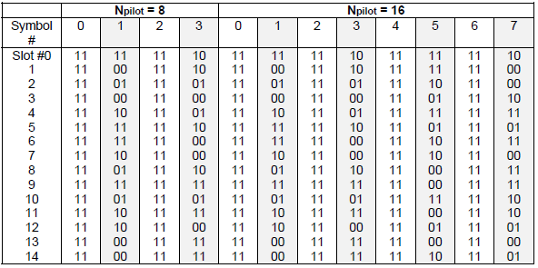
25.211 Table 19. The pilot pattern changes from slot to slot, so it also carries frame timing.
Npilot = 8 : symbols 0 to 3 in each slot.Npilot = 16 : symbols 0 to 7 in each slot.Even symbols : always 11, while the odd symbols follow a pattern over Slot #0 to 14.
The current 25.211 adds an important limit here. The QPSK slot formats with pilot bits are not supported in this release, so the pilot patterns of Table 19 apply to formats that a network does not use today. The 16QAM slot formats send DTX in the pilot field. The S-CCPCH is also not inner-loop power controlled, which is the main difference from a DPCH. Its timing offset from the P-CCPCH is a multiple of 256 chips, and 0 when it carries BCH.
FACH and PCH : on the same or on separate S-CCPCHs.Rate by slot format : SF 256 down to SF 4.QPSK formats with pilot : listed in Table 18, but not supported in this release.
AICH - Acquisition Indicator Channel
How does a UE learn that the network heard its PRACH preamble? The AICH carries that answer. The network sends an acquisition indicator for each preamble signature it detected, in the access slot that matches the preamble.
The diagram below shows the AICH as a run of 15 access slots, AS #0 to AS #14, which together last 20 ms. One access slot is expanded to show its two parts.
< 25.211 - Figure 21: Structure of Acquisition Indicator Channel (AICH) >
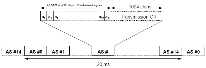
25.211 Figure 21. Each access slot carries acquisition indicators for all 16 signatures at once, followed by a gap with no transmission.
AS #0 to AS #14 : 15 access slots over 20 ms, 5120 chips each.AI part : 4096 chips, 32 real-valued signals a0 to a31.Transmission Off : the last 1024 chips of the access slot.
The AICH uses SF 256 and the P-CPICH as phase reference. Each acquisition indicator AIs takes the value +1, -1 or 0 for signature s. For a PRACH message, +1 is a positive acknowledgement and -1 is a negative one. The 32 signals are the sum of all indicators, each multiplied by its own signature sequence from 25.211 Table 22. Later releases reuse the AICH for E-DCH in CELL_FACH. There, extended acquisition indicators point the UE to one of the common E-DCH resources.
One access slot, two frames : the 15 access slots span 20 ms.AI values : +1 ACK, -1 NACK, 0 no answer.Extended AI : resource selection for common E-DCH.
DPCH - Dedicated downlink physical channels
The DPCH is the dedicated channel of R99. It carries the DCH of one UE, together with the layer 1 control for that UE. The question is how data and control share one slot.
The diagram below shows the answer: data and control are time multiplexed inside every 2560 chip slot. The labels on top show which fields belong to the DPDCH and which to the DPCCH.
< 25.211 - Figure 9: Frame structure for downlink DPCH >
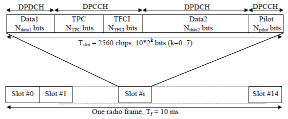
25.211 Figure 9. The downlink DPCH interleaves DPDCH data and DPCCH control inside each slot.
DPDCH : Data1 with Ndata1 bits and Data2 with Ndata2 bits.DPCCH : TPC with NTPC bits, TFCI with NTFCI bits and Pilot with Npilot bits.Slot size : 10 x 2k bits with k = 0 to 7, so SF goes from 512 down to 4.
25.211 Table 11 lists every downlink DPCH slot format. The table is long, so it is shown in two parts.
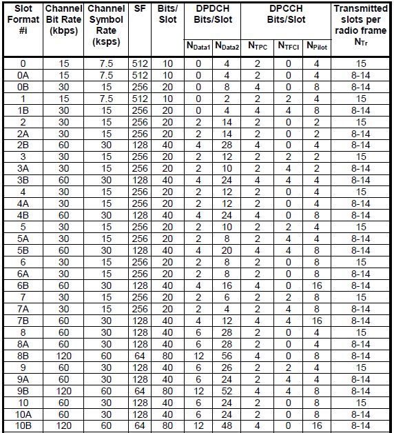
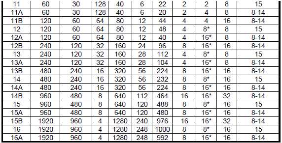
25.211 Table 11. Each slot format fixes the SF and the split between data and control, and the A and B variants are for compressed mode.
Numbered formats 0 to 16 : normal mode, NTr = 15 transmitted slots per radio frame.A formats : compressed mode by higher layer scheduling, same SF, 8 to 14 transmitted slots.B formats : compressed mode by SF reduction, half the SF and double the field sizes.Star on NTFCI : DTX in the TFCI field when TFCI is not used.Not in the picture : the current table adds slot formats 17 and 18, SF 256 and SF 128 with only data and TPC bits and 8 to 15 transmitted slots. They are used only when higher layers configure DL_DCH_FET_Config, for frame early termination on the downlink DCH.
Two kinds of rows appear for most SFs: with TFCI, for several simultaneous services, and without TFCI, for fixed rate services. The UTRAN decides whether to send TFCI, so every UE must support it. SF 512 exists only here, in slot formats 0, 0A and 1. It gives the lowest rate for a DPCH that carries little more than control. 25.211 also limits compressed mode by SF reduction: it is not supported for SF 4, and for SF 512 only with TFCI.
SF 512 to 4 : the widest range of any downlink channel.TFCI optional : chosen by the UTRAN, supported by every UE.A and B formats : for compressed mode.
HS-SCCH - HS Shared Control Channel
A UE cannot decode HS-PDSCH without knowing which codes, which modulation and which transport block size to expect. The HS-SCCH tells it, and it starts 2 slots before the HS-PDSCH it describes.
HS-SCCH is to carry the control information for HS-PDSCH and it has fixed rate of 60 kbps and spreading factor of 128.
<25.211-Figure 26A: Subframe structure for the HS-SCCH >
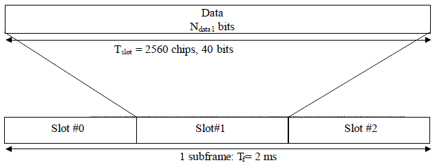
25.211 Figure 26A. One HS-SCCH subframe is 2 ms, three slots of 40 bits each.
Slot : Tslot = 2560 chips, 40 bits, all of them data.Subframe : Slot #0 to Slot #2, Tf = 2 ms.
HS-SCCH Type 1 which is normally used for HSDPA in non-MIMO configuration has structure as shown below (See 25.212 4.6 Coding for HS-SCCH type 1 for details)
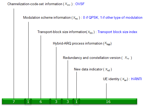
HS-SCCH type 1 information, 21 bits of control plus the 16 bit UE identity.
Channelization-code-set information : 7 bits, the OVSF codes of the HS-PDSCH.Modulation scheme information : 1 bit, 0 for QPSK and 1 for the other modulations.Transport-block size information : 6 bits, a transport block size index.Hybrid-ARQ process information : 3 bits.Redundancy and constellation version : 3 bits.New data indicator : 1 bit.UE identity : 16 bits, the H-RNTI.
25.212 clause 4.6.3 splits these fields into two parts. Part 1 is the code set and the modulation, 8 bits, and it is sent in the first slot. Part 2 is the rest and is sent in the second and third slots. The UE identity is not sent as a field. Instead it masks the coded bits of part 1 and is included in the CRC of part 2, so a UE checks every HS-SCCH in its set against its own H-RNTI. Because the HS-PDSCH starts 5120 chips after the HS-SCCH, the UE decodes part 1 in time to set up the right codes and demodulator.
SF 128, 60 kbps : one HS-SCCH subframe per HS-DSCH TTI.Part 1 in slot 0 : codes and modulation arrive before the HS-PDSCH.H-RNTI as a mask : only the addressed UE decodes the HS-SCCH correctly.
HS-PDSCH - High Speed Physical Downlink Shared Channel
HS-PDSCH is the physical downlink channel that carries HSDPA user data. One HS-PDSCH corresponds to one channelization code of SF(Spreading Factor) 16. Depending on UE capability, multiple HS-PDSCH (i.e, multiple channelization code) can be transmitted simultaneously.
The frame structure of HS-PDSCH is shown below. The modulation scheme for this channel can be QPSK, 16 QAM, 64 QAM. Depending the modulation scheme, M in the following diagram varies. That is, M becomes 2 when the modulcation scheme is QPSK, it becomes 4 for 16 QAM and it become 6 for 64QAM.
< 25.211-Figure 26B: Subframe structure for the HS-PDSCH >
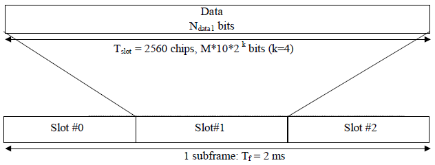
25.211 Figure 26B. The HS-PDSCH has only a data field, so all of its layer 1 information arrives on the HS-SCCH.
Slot : M x 10 x 2k bits with k = 4, which is SF 16.Subframe : Slot #0 to Slot #2, Tf = 2 ms.
The slot format for HS-PDSCH (i.e, Data field) are as shown below.
< 25.211-Table 26: HS-DSCH fields >

25.211 Table 26. The symbol rate is always 240 ksps at SF 16, and only the modulation changes the bit rate.
Slot format 0, QPSK : 480 kbps, 960 bits per subframe.Slot format 1, 16QAM : 960 kbps, 1920 bits per subframe.Slot format 2, 64QAM : 1440 kbps, 2880 bits per subframe.
These rates are per code. With 15 codes and 64QAM, the channel bit rate is 15 x 1440 = 21.6 Mbps before channel coding, for one cell without MIMO. The HS-PDSCH carries no pilot, TPC or TFCI. So the UE depends on the CPICH for its phase reference, on the HS-SCCH for the transport format, and on an associated DPCH or F-DPCH for power control of its uplink.
SF 16 always : rate changes only with modulation and the number of codes.No layer 1 fields : everything is signalled on the HS-SCCH.Multi-code : the number of codes depends on the UE category.
Reference
[1] 3GPP TS 25.211 v19.0.0 - clauses 5.3.2, 5.3.3 and 7.1, Figures 9, 13, 15, 17, 18, 21, 26A, 26B and 29, Tables 11, 18, 19 and 26
[2] 3GPP TS 25.212 v19.0.0 - clause 4.6, Coding for HS-SCCH type 1
[3] 3GPP TS 25.213 - scrambling code groups
[4] 3GPP TS 25.214 v19.0.0 - Annex C, Cell search procedure