Comparing to LTE MAC structure, UMTS MAC operation and MAC PDU structure is very complicated. I don't think it is complicated because UMTS MAC is doing more things than LTE MAC. (In terms of functionalility, I think LTE MAC is doing more than UMTS MAC). I think most of the complexity of UMTS MAC structure come from the design and the complexity of the transport channel. Often, things get very confusing and as a result log analysis/troubleshooting gets very tricky. Followins are the topics that will be covered in this page.
MAC-d is the MAC entity for the dedicated logical channels, DCCH and DTCH. There is one MAC-d per UE, in the UE and in the serving RNC. It maps these channels onto DCH by itself, or it hands them to MAC-c/sh/m, MAC-hs/ehs or MAC-e/es for the common and high speed transport channels. The page ends with two hex dumps decoded by hand, one on FACH and one on RACH.
- Overview on MAC-d in UTRAN
- Overview on MAC-d in UE
- General Structure of MAC-d PDU
- MAC PDU Structure for Each Logical Channel and Transport Channel
- Examples
- Reference
Overview on MAC-d in UTRAN
As you see in 25.321 - Figure 4.2.4-1 (Overview on MAC Layer in UTRAN), regardless of whether it is for R99, HSDPA(R5), HSUPA(R6), HSPA+ (R7), every MAC data goes through MAC-d sublayer somewhere along it's path. However the data flow within this sublayer differs among R99, R5, R6, R7 and differs depending on whether it is uplink (From UE to UTRAN) or downlink (From UTRAN to UE).
To help you understand the path for each case, I colored the figure from 25.321 according to each of the case.
Red path represent the case for R99 and it applies to both Uplink and downlink. But when you want to follow the uplink path, you have to read the figure from bottom to top and for downlink you have to read from top to bottom. The important thing to remember is that for R99 MAC-d is a whole of MAC layer and the MAC flow does not go through any further processing.
Blue path indicate the path for HSDPA(R5) and HSPA+(R7). As you see, the data for HSDPA, HSPA+ goes through MAC-d with a very little processing and are passed to MAC-hs (HSDPA) or MAC-ehs(HSPA+) for further detailed processing. You will go back to this processing later in this section.
Green path shows the path for HSUPA, meaning this is an uplink path. You have to follow from bottom (from the point labeled 'from MAC-es/MAC-is) to top.
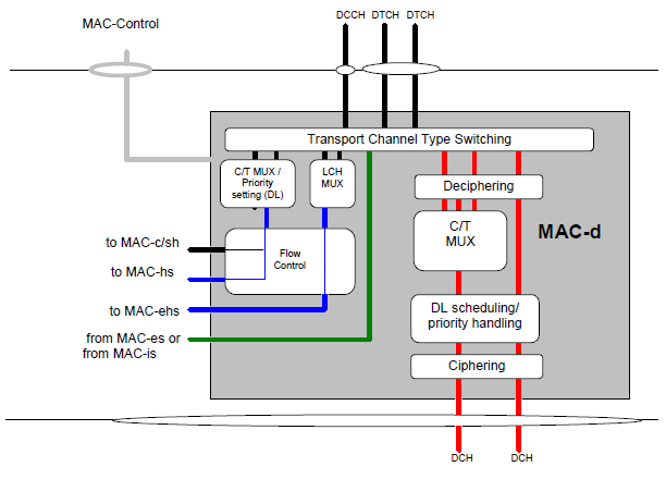
< 25.321 - Figure 4.2.4.2-1 : UTRAN side MAC architecture / MAC-d details >
Transport Channel Type Switching : the top box, which every path passes through. When RRC decides it, this block moves one logical channel between a common and a dedicated transport channel.C/T MUX / Priority setting - DL : adds the C/T field when several dedicated logical channels share one transport channel or one MAC-d flow. It also sets the priority of DCCH and DTCH data sent towards MAC-c/sh and MAC-hs.LCH MUX : used instead of C/T MUX towards MAC-ehs. It tags each block of MAC-d PDUs with the LCH-ID of its logical channel, which MAC-ehs carries in its own header.Flow Control : limits the buffering between MAC-d and MAC-c/sh/m, or MAC-hs/ehs when there is no MAC-c/sh/m in between. The green path from MAC-es or MAC-is needs none, because MAC-es and MAC-is sit in the SRNC with MAC-d.Deciphering, C/T MUX, DL scheduling/priority handling and Ciphering : the red DCH path. MAC-d ciphers only transparent mode RLC data. RLC ciphers the AM and UM data itself.
The ciphering point is the one to remember from Figure 4.2.4.2-1. A DCH carrying a TM radio bearer, such as an AMR voice bearer, is ciphered in MAC-d, so a log decoder has to decipher at the MAC layer for that bearer. For AM and UM bearers the MAC-d SDU is already ciphered by RLC.
One MAC-d per UE in the SRNC : MAC-c/sh/m is one per cell, and MAC-hs/ehs and MAC-e are in the Node B.MAC-d does all the work only on DCH : on the HSDPA and HSUPA paths it only multiplexes and passes the data on.MAC-d ciphers only TM data : AM and UM data arrive from RLC already ciphered.
Overview on MAC-d in UE
As you see in Figure 4.2.3-1 (Overview on MAC Layer in UE), regardless of whether it is for R99, HSDPA(R5), HSUPA(R6), HSPA+ (R7), every MAC data goes through MAC-d sublayer somewhere along it's path. However the data flow within this sublayer differs among R99, R5, R6, R7 and differs depending on whether it is uplink (From UE to UTRAN) or downlink (From UTRAN to UE).
To help you understand the path for each case, I colored the figure from 25.321 according to each of the case.
Red path represent the case for R99 and it applies to both Uplink and downlink. But when you want to follow the uplink path(from UE to UTRAN), you have to read the figure from top to bottom and for downlink (from UTRAN to UE) you have to read from bottom to top. The important thing to remember is that for R99 MAC-d is a whole of MAC layer and the MAC flow does not go through any further processing.
Blue path indicate the path for HSDPA(R5) and HSPA+(R7). As you see, the data for HSDPA, HSPA+ goes through MAC-d with a very little processing and are passed to MAC-hs (HSDPA) or MAC-ehs(HSPA+) for further detailed processing. You will go back to this processing later in this section.
Green path shows the path for HSUPA in the UE. It goes from the top down to the point labeled 'to MAC-e/es or to MAC-i/is', because in the UE the E-DCH is an uplink path.
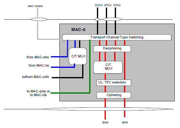
< 25.321 - Figure 4.2.3.2-1 : UE side MAC architecture / MAC-d details >
Put Figure 4.2.3.2-1 next to Figure 4.2.4.2-1 above, and you will find three differences. The UE figure has no Flow Control block, because there is no Iub or Iur between the MAC entities of a UE. It has no LCH MUX, because MAC-ehs in the UE reads the LCH-ID itself. And it has a UL: TFC selection block on the red path instead of the DL scheduling block.
UL: TFC selection : the UE picks the TFC for its DCHs from the TFCS that RRC configured. This is where the UE decides how many transport blocks each DCH sends in the next TTI.C/T MUX on the left : the figure draws the lines from MAC-hs and MAC-ehs and the line to and from MAC-c/sh into it. Towards MAC-ehs, 25.321 says the C/T MUX is not used. The black line to and from MAC-c/sh is the CELL_FACH path, where MAC-c/sh/m adds the TCTF and the UE-Id.Green line : goes to MAC-e/es or MAC-i/is with no C/T MUX. A MAC-d PDU on E-DCH has no MAC-d header, because MAC-e and MAC-i identify the logical channel in their own headers.
The UE has one MAC-d : it serves every DCCH and DTCH of the UE, whatever the transport channel.Uplink reads top to bottom in the UE figure : and bottom to top in the UTRAN figure.
General Structure of MAC-d PDU
The MAC PDU for R99 (marked in Red path) has following structure. (Note that this PDU applies only to R99 MAC PDU and does not apply to HSDPA, HSUPA PDU. ) This is a generic format which contains all the possible fields in the header, but depending on logical channels and mapping type, the header structure gets different. We will see the details for each specific cases in next section.
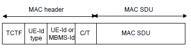
< 25.321 - Figure 9.1.2-1 : MAC PDU >
|
Field |
Field Name |
Bits |
Description |
|
TCTF |
Target Channel Type Field |
1~8 |
The purpose of this field is to indicate the logical channel type (class) and meaning and number of bits for this field differs depending on the logical channel type. (Refer to Table 9.2.1-1, 9.2.1-2, 9.2.1-4 for the details. These tables are all from 3GPP 25.321) |
|
UE-Id Type |
UE-Id Type |
2 |
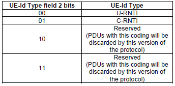
This field indicate UE ID type. (There are only two UE types as shown in table 9.2.1-7) |
|
UE-Id |
UE Identification |
16 or 32 |
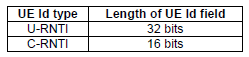
This field indicate UE ID. The bit length of the ID differs depending on which UE-Id type is used in "UE-id Type" field. |
|
C/T |
C/T Field |
4 |
C/T field indicate the logical channel number for the PDU and the meaning of this value is listed in Table 9.2.1-5a. |
The detailed value and meaning for each field are defined by various tables as shown below.
< 25.321 - Table 9.2.1-1 : Coding of the Target Channel Type Field on FACH for TDD >
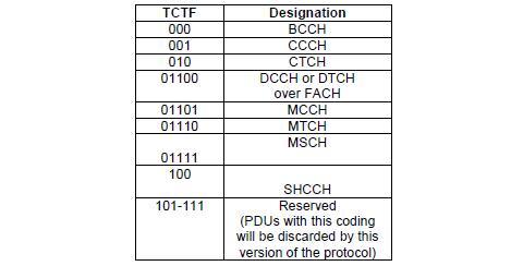
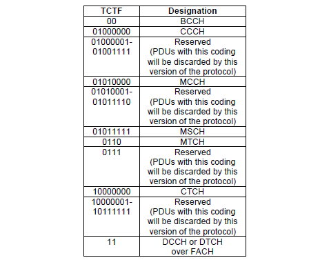
< 25.321 - Table 9.2.1-2 : Coding of the Target Channel Type Field on FACH for FDD >
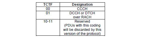
< 25.321 - Table 9.2.1-4 : Coding of the Target Channel Type Field on RACH for FDD >
< 25.321 - Table 9.2.1-7 : UE-ID Type field definition >
< 25.321 - Table 9.2.1-6 : Lengths of UE Id field >
< 25.321 - Table 9.2.1-5a : Structure of the C/T field >
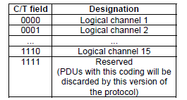
Two details in these tables matter when you decode by hand. First, the UE-Id position in Figure 9.1.2-1 can hold an MBMS-Id instead. That is a 4 bit field used only for MTCH on FACH in the downlink. Second, the UE-Id type tells you the length of the next field. 00 means a 32 bit U-RNTI, and 01 means a 16 bit C-RNTI. The U-RNTI is never used in the uplink, so a RACH PDU always carries a C-RNTI.
The TCTF is read first : its value tells you whether a UE-Id type follows at all.The UE-Id type sets the UE-Id length : 32 bits for U-RNTI, 16 bits for C-RNTI.The C/T is always 4 bits : 0000 to 1110 are logical channels 1 to 15, and 1111 is reserved.
MAC PDU Structure for Each Logical Channel and Transport Channel
MAC-d PDU structure takes various different form depending on the type of Logical channel and the mapping between the logical channel and transport channel. In this section, I will summarize the MAC PDU structures for all the possible combinations. These are based on 25.321 - 9.2.1 MAC PDU: Parameters of the MAC PDU header (not HS-DSCH or E-DCH) and MAC-d PDU header (HS-DSCH and E-DCH)
Strictly, only DTCH and DCCH pass through MAC-d. CCCH, BCCH and PCCH are handled by MAC-c/sh/m, and BCCH on BCH by MAC-b. They are listed here because the same header fields appear on the same transport channels, and a FACH or RACH decoder has to tell them apart by the TCTF.
DTCH and DCCH
DTCH and DCCH have five header formats, one for each kind of transport channel they can use. The header grows from nothing on a DCH with one logical channel to four fields on RACH and FACH, as the figure below shows.
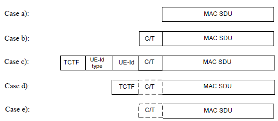
< 25.321 - Figure 9.2.1.1-1: MAC PDU formats for DTCH and DCCH >
a) DTCH or DCCH mapped to DCH, no multiplexing of dedicated channels on MAC:
- no MAC header is required.
b) DTCH or DCCH mapped to DCH, with multiplexing of dedicated channels on MAC:
- C/T field is included in MAC header.
c) DTCH or DCCH mapped to RACH/FACH:
- TCTF field, C/T field, UE-Id type field and UE-Id are included in the MAC header. For FACH, the UE-Id type field used is the C-RNTI or U-RNTI. For RACH, the UE-Id type field used is the C-RNTI.
d) DTCH or DCCH mapped to DSCH or USCH:
- the TCTF field is included in the MAC header. The C/T field is included if multiplexing on MAC is applied.
e) DTCH or DCCH mapped to DSCH or USCH where DTCH or DCCH are the only logical channels:
- The C/T field is included in the MAC header if multiplexing on MAC is applied.
Case b) is the usual one for signalling on DCH. The four SRBs, SRB1 to SRB4, often share one DCH, and the C/T field then tells them apart. Cases d) and e) are TDD only, because DSCH and USCH exist only in TDD.
CCCH
CCCH carries RRC Connection Request on RACH and RRC Connection Setup on FACH. Its header is the TCTF alone, because the UE has no C-RNTI yet and the RRC message carries the UE identity itself.

< 25.321 - Figure 9.2.1.4-1: MAC PDU format for CCCH mapped to RACH/FACH >
BCCH
BCCH has three formats, and the transport channel decides which one applies. Only the FACH case carries a MAC header of its own, the 2 bit TCTF 00 on FDD.
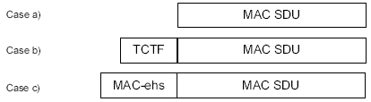
< 25.321 - Figure 9.2.1.2-1: MAC PDU formats for BCCH >
a) BCCH mapped to BCH:
- no MAC header is included.
b) BCCH mapped to FACH:
- the TCTF field is included in MAC header.
c) in FDD and 1.28 Mcps TDD, when BCCH mapped to HS-DSCH
- the MAC-ehs header is included.
PCCH
PCCH on PCH has no MAC header at all, so the MAC PDU is the MAC SDU, as the drawing below shows. When PCCH is mapped on HS-DSCH in FDD or 1.28 Mcps TDD, the MAC-ehs header is added instead.

Only case c) of DTCH and DCCH carries four fields : TCTF, UE-Id type, UE-Id and C/T, on RACH and FACH.A DCH with one logical channel has no MAC header : the MAC PDU is the RLC PDU.CCCH and BCCH on FACH carry only the TCTF : PCCH on PCH carries nothing.
Examples
The two examples below take a hex dump from a log and split it into the header fields defined above. Read the TCTF first, because it decides which fields follow. Then count the bits of each field in order.
Example - Mapping DCCH onto FACH
This examaple came from the Cell Update Confirm (NB -> UE) message. The network sent it on FACH to a UE in CELL_FACH, so the DCCH carries the full case c) header in front of the RLC PDU. The dump below starts at the first bit of that header.
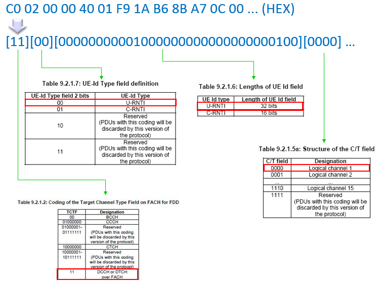
The first 2 bits, 11, are the TCTF for DCCH or DTCH over FACH. The next 2 bits, 00, say that a U-RNTI follows. The 32 bit U-RNTI is 0x00200004. Its first 12 bits are the SRNC identity, 2, and its last 20 bits are the S-RNTI, 4. The C/T is 0000, which is logical channel 1.
The whole header is 2 + 2 + 32 + 4 = 40 bits, which is exactly 5 octets. So the MAC SDU, the RLC UM PDU, starts on an octet boundary at 0x01. The U-RNTI fits the spec here. 25.321 allows it only for DCCH on RLC UM, that is SRB1, in the downlink. The table images use the older numbering with dots, such as Table 9.2.1.7, and the TCTF table in the image is from a release before MBMS. The FDD FACH code 11 is the same in the current release.
Example - Mapping CCCH onto RACH
The second dump is uplink. On RACH the TCTF is only 2 bits, and CCCH carries no other MAC header field, so the decode stops after the first 2 bits.
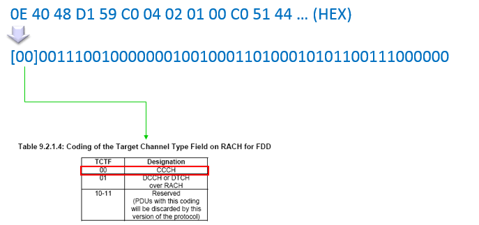
The first byte is 0x0E, so the first 2 bits are 00, which is CCCH on RACH. Everything after them is the MAC SDU, that is the transparent mode RLC PDU with the UL-CCCH message. Unlike the FACH example, this SDU starts 2 bits into the first octet. So a byte-wise decoder of the RRC message has to shift the whole dump by 2 bits first.
DCCH on FACH with a U-RNTI has a 40 bit header : TCTF 2, UE-Id type 2, U-RNTI 32 and C/T 4 bits.CCCH on RACH has a 2 bit header : the RRC message starts at bit 2, not on an octet boundary.The U-RNTI splits into SRNC identity and S-RNTI : 12 bits and 20 bits.
Reference
[1] 3GPP TS 25.321 v19.0.0 - clause 4.2.3.2 and 4.2.4.2, the MAC-d entity, clause 9.1.2 and 9.2.1, the MAC PDU and its header parameters
[2] 3GPP TS 25.331 v19.0.1 - clause 10.3.3.47, U-RNTI