Following is the brief PHY channel structure for R99 (WCDMA) network. As the technolgy evolve, you will see a couple of new Physical Channel is added and the new channel usually has shorter TTI.
In R99, a UE in a connection sends and receives its user data and its signalling on dedicated channels. The downlink uses the DPCH, and the uplink uses the DPDCH and the DPCCH. Both directions share the same timing: a 10 ms radio frame of 15 slots, and a slot of 2560 chips. Let's go through the slot structure first, then compare the two directions, and then look at what the later releases added on top of this frame.
- What does a R99 dedicated channel slot carry ?
- How do the uplink and downlink slot formats compare ?
- What did later releases add on top of the R99 frame ?
- Reference
What does a R99 dedicated channel slot carry ?
Every slot of a dedicated channel carries two kinds of bits. The DPDCH part carries the DCH, which is the data coming from Layer 2 and above. The DPCCH part carries Layer 1 control: known pilot bits, TPC commands and an optional TFCI, plus FBI bits in the uplink. The question for this section is how the two parts share the radio link in each direction.
The diagram below puts the two frame structures from 25.211 around one radio link. At the upper left is 25.211 Figure 9, the frame structure for the downlink DPCH. At the lower right is 25.211 Figure 1, the frame structure for the uplink DPDCH/DPCCH. The arrows in the middle show that each direction carries both a DPDCH and a DPCCH.
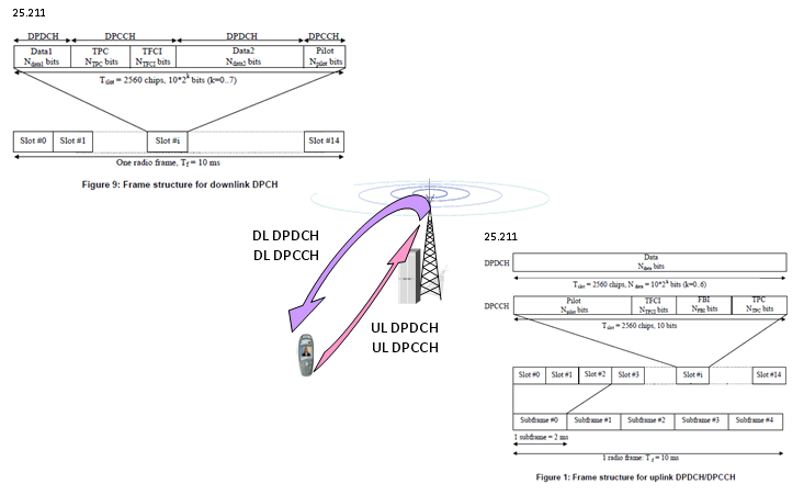
R99 dedicated physical channels. The downlink puts data and control one after the other inside one slot, while the uplink sends them at the same time on two code channels.
The downlink DPCH is a time multiplex : One slot runs Data1, TPC, TFCI, Data2 and Pilot in that order. So the downlink DPCH is a downlink DPDCH and a downlink DPCCH taking turns inside the same slot.The downlink slot size depends on k : A slot holds 10 x 2k bits with k = 0 to 7. The spreading factor is SF = 512/2k, so it runs from 512 down to 4.The uplink DPDCH and DPCCH run in parallel : The uplink draws two separate slots of the same 2560 chips. The DPDCH carries only data, and the DPCCH carries Pilot, TFCI, FBI and TPC. The two are I/Q code multiplexed, each with its own channelisation code.Only the uplink DPDCH changes size : A DPDCH slot holds 10 x 2k bits with k = 0 to 6, so SF = 256/2k runs from 256 down to 4. The DPCCH always uses SF 256 and carries 10 bits per slot.The subframe row is not part of R99 : The row of Subframe #0 to #4 under the uplink slots comes from a later version of 25.211. A subframe is 3 slots, or 2 ms, and it is the timing unit of HS-DSCH and E-DCH. A R99 DCH does not use it.
Why does the uplink not use the same time multiplex as the downlink? 25.211 allows zero, one or several uplink DPDCHs on a radio link, but always exactly one uplink DPCCH. With the DPCCH on its own code, the pilot and the TPC bits keep going in every slot, even when the UE has no data for the DPDCH. So the Node B can still estimate the channel and run power control on a silent uplink.
Each slot is also one power control period. There are 15 slots in 10 ms, so each direction carries 1500 TPC commands per second. This is the fast inner loop power control of WCDMA, and it works only because every slot carries its own TPC field.
A slot is one power control period : Each slot has a TPC field, so both directions can adjust the power 1500 times per second.TFCI is optional in both directions : The UTRAN decides whether a TFCI is sent. A fixed-rate service can go without it, and the slot formats without TFCI give those bits to other fields.Higher layers pick the slot format : The slot format fixes Npilot, NTPC, NTFCI and, in the uplink, NFBI. Higher layers configure it and can reconfigure it.
How do the uplink and downlink slot formats compare ?
The two directions follow different rules for the spreading factor and for the control fields. When you check a slot format in a log, you need the rule of the right direction. The table below puts the numbers from 25.211 side by side.
Item |
Downlink DPCH |
Uplink DPDCH / DPCCH |
Data and control |
Time multiplex inside one slot |
I/Q code multiplex on separate codes |
Bits per slot |
10 x 2k, k = 0 to 7 |
DPDCH: 10 x 2k, k = 0 to 6. DPCCH: 10 |
Spreading factor |
512/2k, from 512 to 4 |
DPDCH: 256/2k, from 256 to 4. DPCCH: always 256 |
Layer 1 control fields |
TPC, TFCI, Pilot |
Pilot, TFCI, FBI, TPC |
Channels per radio link |
One DPCH, with more codes in multi-code transmission |
Zero, one or several DPDCHs, and exactly one DPCCH |
Slot format table in 25.211 |
Table 11 |
Table 1 for DPDCH, Table 2 for DPCCH |
Let's read one row of each table. Uplink DPCCH slot format 0 has Npilot = 6, NTPC = 2, NTFCI = 2 and NFBI = 0, which fills the 10 bits of the slot. Slot format 1 drops the TFCI and uses Npilot = 8 instead. Downlink slot format 0 runs at SF 512 with 10 bits per slot. Its DPDCH part gets NData1 = 0 and NData2 = 4, and its DPCCH part gets NTPC = 2 and NPilot = 4, with no TFCI.
Why does the downlink SF range start at 512 when the uplink starts at 256? The answer is the modulation. The downlink DPCH uses QPSK, so SF 512 gives 7.5 ksps and 15 kbps. The uplink DPDCH and DPCCH each sit on one branch with one bit per symbol, so SF 256 gives 15 ksps and 15 kbps. Both lowest rates therefore carry 10 bits per slot.
Some slot formats carry the letter A or B. These are the compressed mode versions of a normal slot format. In the uplink, the choice between A and B depends on how many slots each frame transmits. In the downlink, format B is used in frames compressed by spreading factor reduction, and format A in frames compressed by higher layer scheduling.
Check the direction before the SF : SF 256 means 20 bits per slot on the downlink DPCH, but 10 bits per slot on the uplink DPDCH.The uplink DPCCH never changes its SF : Whatever the data rate, the DPCCH stays at SF 256 with 10 bits per slot. Only the split among pilot, TPC, TFCI and FBI changes with the slot format.Formats A and B belong to compressed mode : A log that shows them is a sign of a transmission gap, for example for inter-frequency or inter-RAT measurement.
What did later releases add on top of the R99 frame ?
The introduction says that new physical channels came with each release, and that they usually have a shorter TTI. Let's check that against 25.211 and 25.212. The 10 ms frame and the 2560 chip slot of R99 stay, and the later channels are built from them.
A R99 DCH has a TTI of 10, 20, 40 or 80 ms, and 25.212 now allows the 80 ms TTI for a DCH only with SF 512. So even the shortest DCH TTI spans a whole radio frame. HSDPA and HSUPA added the sub-frame, which is 3 slots or 7680 chips, that is 2 ms. The sub-frame is the basic time interval of HS-DSCH and E-DCH. The HS-DSCH uses it as its TTI, and the E-DCH can use a 2 ms or a 10 ms TTI. This is where the shorter TTI in the introduction comes from.
The list of dedicated channels also grew. On the uplink, 25.211 now has seven dedicated physical channels: DPDCH, DPCCH, S-DPCCH, DPCCH2, E-DPDCH, E-DPCCH and HS-DPCCH. On the downlink it has five: DPCH, F-DPCH, E-RGCH, E-HICH and F-TPICH. For the R99 structure, the F-DPCH matters most. It is a special case of the downlink DPCCH that carries only TPC commands. So a UE whose downlink data runs on HS-DSCH can keep uplink power control without a full downlink DPCH.
The R99 frame is still the base : The 10 ms radio frame, the 15 slots and the 2560 chip slot are the same in the current 25.211.The shorter TTI comes from the sub-frame : Three slots make one 2 ms sub-frame, which HS-DSCH and E-DCH use for scheduling.F-DPCH keeps only the power control part : It keeps the TPC field of the DPCH and drops the data, TFCI and pilot fields.
Reference
- 3GPP TS 25.211 v19.0.0 : Physical channels and mapping of transport channels onto physical channels (FDD)
- 3GPP TS 25.212 v19.0.0 : Multiplexing and channel coding (FDD)