Let's suppose you are a NodeB. You will getting various signals from many different users (UEs) all at the same time. Then how would you differentiate the incoming signals into separate users at the very low level of your hardware ?. Of course you can figure out exactly which user you are dealing with at higher layer with various type of user ID (UE ID), but my question is how to figure out each user at PHY layer ?
Now let's assume that you are a UE. You may be hearing many signals from multiple NodeBs simultaneously. Then how would you differentiate the incoming signals into separate NodeB at the very low level of your hardware ?
The answer to both of the question is same. It is "Scrambling Code". By using the scrambling code, NodeB can separate signals coming simultaneously from many different UEs and UE can separate signals coming simultaneously from many different NodeB.
Let's follow the scrambling code through the page in the order a signal meets it. First we place it in the PHY processing chain and list the code types. Then we go channel by channel through PRACH, the uplink DPCH and the downlink, each time with the 25.213 figure and the RRC message that tells the UE which code to use.
- Where does scrambling sit in the PHY chain ?
- Which types of scrambling code are there ?
- What else does the scrambling code give you ?
- How is the PRACH scrambled ?
- How are the uplink dedicated channels scrambled ?
- How are the downlink channels scrambled ?
- Reference
Where does scrambling sit in the PHY chain ?
A WCDMA transmitter multiplies the data by two different codes, one after the other. It is easy to mix them up, because both run at the chip rate. So before looking at the code types, let's place the scrambling code in the chain and separate it from the channelisation code.
Now let's look into how/where the scrambling code works. Following illustration shows the procedure about the data processing in physical layer. As you see in the following diagram, "Scrambling" happens at the chip rate of the signal processing. Since the chip rate of the scrambling code is the same as the chip rate of the chanelization code scrambling does not change the signal data rate.
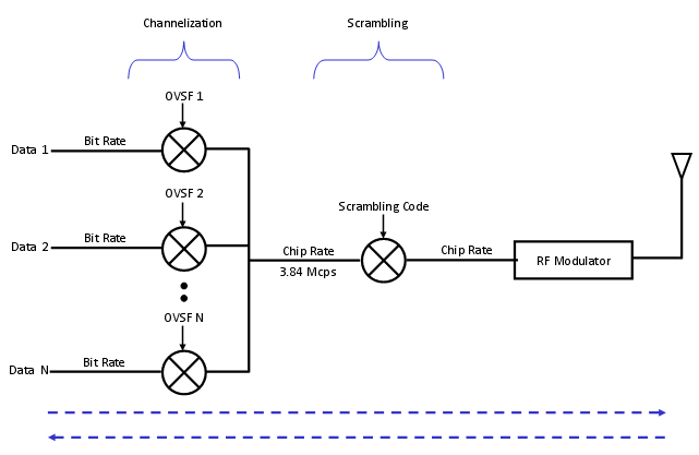
Channelization and scrambling in WCDMA. The OVSF codes change the rate from bit rate to chip rate, and the scrambling code keeps the chip rate unchanged.
Channelization : each data stream, Data 1 to Data N, is multiplied by its own OVSF code. This step turns the bit rate into the chip rate.Summing : the spread streams are added into one signal at 3.84 Mcps.Scrambling : the summed signal is multiplied by one scrambling code. The input and the output both run at the chip rate.RF Modulator : the scrambled chips go to the RF modulator and the antenna. The dashed arrows at the bottom show that the receiver undoes the same steps in reverse order.
The order matters for the receiver. The receiver first removes the scrambling code, which picks out one transmitter. Only then does it despread with the OVSF code, which picks out one channel of that transmitter.
Two codes, two jobs : the OVSF code separates channels from one transmitter, and the scrambling code separates transmitters.Scrambling adds no bandwidth : it works chip by chip on a signal that is already at 3.84 Mcps.
Which types of scrambling code are there ?
25.213 defines different code families for the uplink and the downlink, and the uplink has two of them. The choice depends on the direction and, in the uplink, on the receiver the NodeB uses. The numbers of codes also differ a lot between the two directions.
A specific bit sequence which is used for scrambling is called 'Scrambling code'.
There are two types of scrambling codes : long scrambling code and short scrambling code. Long scrambling code(38400 chips) derived from Gold codes and short codes (256 chips) derived from S(2) codes.
Then which type of scrambling code we use ?.
In downlink, only long codes are used.
In uplink direction long codes are used for node B using Rake reciever and short codes are used for NodeB using multiuser detection or interference cancellation recievers. With short codes the implementation of cyclic processing structure is simpler.
The code counts come from 25.213. In the uplink, 25.213 subclause 4.3.2.1 defines 224 long and 224 short scrambling codes, so every UE in a network can get its own code. In the downlink, subclause 5.2.2 can generate 218-1 = 262,143 codes, but only codes 0 to 8191 are used. They form 512 sets. Each set has one primary scrambling code, number 16 x i for i = 0 to 511, and 15 secondary scrambling codes, numbers 16 x i + k for k = 1 to 15.
The 512 primary codes are further divided into 64 scrambling code groups of 8 primary codes each. This grouping serves cell search: the UE finds the code group from the SCH first, and then tests only 8 primary codes. Each cell has exactly one primary scrambling code. The table below puts the numbers side by side.
Direction | Code type | Number of codes | 25.213 |
Uplink | Long, Gold based | 224, each 38400 chips per frame | 4.3.2.2, 4.3.2.4 |
Uplink | Short, S(2) based | 224, 256 chip period | 4.3.2.3, 4.3.2.4 |
Uplink PRACH | Long, preamble and message part | 8192 | 4.3.2.5, 4.3.3.2 |
Downlink | Gold, primary | 512, numbers 16 x i | 5.2.2 |
Downlink | Gold, secondary | 15 per primary code, numbers 16 x i + k | 5.2.2 |
The uplink separates UEs : with 224 codes, the network can give every UE its own long or short code.The downlink separates cells : a cell is identified at the physical layer by one of 512 primary scrambling codes.Secondary codes add OVSF space : a cell can put some channels under a secondary scrambling code when its OVSF tree under the primary code is full.
What else does the scrambling code give you ?
Even though main role of the scrambling code is to separate multiple signals into the one from each transmitter, it has several additional side effect (I mean 'good side effect').
It can improve Synchronization. The scrambling code is designed to have relatively high auto-correlation property and you can use the result of high-auto correlation to tune the synchronization timing.
It enables you to reuse the spreading code. Spreading code is used to match the bit rate data into chip rate (3.84 Mcps) signal and also for separating one specific channel from another. For this separation, it uses a special set of spreading code which has the orthogonal to each member of the set. This set of spreading code being used in WCDMA is called OVSF (Orthogonal Variable Spreading Factor). But the number of OVSF is not infinite. We only have a finite number of OVSF codes which may put us in short of those codes.
If two different data stream uses the same OVSF codes, the receive cannot differentiate these two. But if the two channels are using different scrambling codes even though they are using the same spreading code, the two data can be separated. The two data stream will go to different reciever path by scrambling process (unscrambling process more accurately speaking).
This is exactly what the secondary scrambling codes of the downlink are for. The OVSF codes under one scrambling code are orthogonal to each other, but the codes under two different scrambling codes are not. So a channel moved to a secondary scrambling code gets a fresh OVSF tree, but it also loses the orthogonality to the channels under the primary code. That is why a network uses the primary scrambling code as long as its OVSF tree has room.
Scrambling reuses the OVSF tree : the same OVSF code can serve two channels when they sit under different scrambling codes.Reuse costs orthogonality : channels under different scrambling codes interfere with each other like signals from another cell.Good correlation helps the receiver : the correlation property of the scrambling code is what the receiver uses to find the frame timing.
How is the PRACH scrambled ?
The PRACH is the first uplink transmission of a UE, before the network has given it any dedicated code. So the UE must derive the PRACH scrambling code from what the cell broadcasts. The preamble and the message part both need a code, and 25.213 ties the two together.
Now let's look into the further details of how the scrambling process is really implemented. Here, I will just give you the diagram for each case and the 3GPP specification where you can have further details.
First, let's look into PRACH scrambling part. The overall flow is as follows.
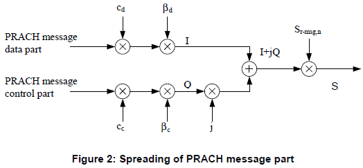
25.213 Figure 2, Spreading of PRACH message part. The data part and the control part are combined into one complex signal and then multiplied by the message part scrambling code.
PRACH message data part : spread by the channelisation code cd, weighted by the gain factor βd, and carried on the I branch.PRACH message control part : spread by cc, weighted by βc, and carried on the Q branch after the multiplication by j.Sr-msg,n : the I+jQ sum is multiplied by the PRACH message part scrambling code number n. The output S goes to the modulator.No preamble : the figure covers only the message part. The preamble is built separately, from a preamble scrambling code and a signature.
For the details of PRACH Preamble part of scrambling code, refer to 25.213, section 4.3.3.2 Preamble scrambling code.
For the details of PRACH message part of scrambling code, refer to 25.213, section , 4.3.2.5 PRACH message part scrambling code
The two subclauses fit together as follows. There are 8192 PRACH preamble scrambling codes, in 512 groups of 16. The group belongs to the downlink primary scrambling code m of the cell. The k-th preamble code in that cell has the number n = 16 x m + k, with k = 0 to 15. The message part then uses the same number n, and its code is the same long sequence started 4096 chips later.
So the UE needs only two numbers to scramble a PRACH. The first is the primary scrambling code of the cell, which it already found during cell search. The second is k, which the cell broadcasts.
How UE would know which scrambling code it has to use for PRACH ? That information is carried by SIB5 as follows (see the IE marked in red)
Decoded RRC message from a tester log,
SysInfoType5 ::= SEQUENCE [000]
  +-sib6indicator ::= BOOLEAN [FALSE]
  +-pich-PowerOffset ::= INTEGER (-10..5) [-5]
  +-modeSpecificInfo ::= CHOICE [fdd]
  | +-fdd ::= SEQUENCE
  |   +-aich-PowerOffset ::= INTEGER (-22..5) [5]
  +-primaryCCPCH-Info ::= CHOICE OPTIONAL:Omit
  +-prach-SystemInformationList ::= SEQUENCE OF SIZE(1..maxPRACH[16]) [1]
  | +-PRACH-SystemInformation ::= SEQUENCE [11101]
  |   +-prach-RACH-Info ::= SEQUENCE
  |   | +-modeSpecificInfo ::= CHOICE [fdd]
  |   |   +-fdd ::= SEQUENCE
  |   |     +-availableSignatures ::= BIT STRING  [1111111111111111]
  |   |     +-availableSF ::= ENUMERATED [sfpr64]
  |   |     +-preambleScramblingCodeWordNumber ::= INTEGER (0..15) [0]
  |   |     +-puncturingLimit ::= ENUMERATED [pl1]
  |   |     +-availableSubChannelNumbers ::= BIT STRING  [111111111111]
In this capture, preambleScramblingCodeWordNumber is 0, so the UE uses k = 0. If the cell has the primary scrambling code 9 that appears in the downlink captures below, the preamble code number is 16 x 9 + 0 = 144. The capture also shows sib6indicator FALSE, which means SIB6 is not broadcast and the UE takes its PRACH information from SIB5. The listing below shows the IE in the current 25.331, and its range of 0 to 15 matches the 16 codes of a group.
Following is based on
PreambleScramblingCodeWordNumber ::= INTEGER (0..15)
The cell broadcasts k, not the code : preambleScramblingCodeWordNumber selects one of the 16 codes tied to the primary scrambling code.Preamble and message part share one number : the message part code is the same long sequence as the preamble code, offset by 4096 chips.Cell search comes first : the UE cannot build a PRACH code before it knows the primary scrambling code of the cell.
How are the uplink dedicated channels scrambled ?
After the connection setup, the UE has dedicated uplink channels, and each UE needs its own code so that the NodeB can separate it from the others. Unlike the PRACH code, this code is not derived from the cell. The network picks it and signals it to the UE.
First, let's look into scrambling process of all other UL channels except PRACH. The overall flow is as follows.
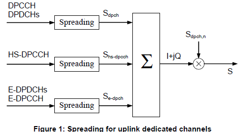
25.213 Figure 1, Spreading for uplink dedicated channels. All dedicated channels of one UE are summed first and then scrambled with a single code, Sdpch,n.
Three spreading blocks : DPCCH and DPDCHs, HS-DPCCH, and E-DPDCHs with E-DPCCH are spread separately, giving Sdpch, Shs-dpch and Se-dpch.One sum : the three outputs are added into one complex signal I+jQ.One scrambling code : the sum is multiplied by Sdpch,n, the uplink scrambling code number n of this UE.
For the details of UL DPCH part of scrambling code, refer to 25.213, section 4.3.2.4 Dedicated physical channels scrambling code.
How UE would know which scrambling code it has to use for UL DPCH ?
This code is determined by the network and informed to UE by rrc Connection Setup and Radio Bearer Setup message as follows.
Decoded RRC message from a tester log,
DL-CCCH-Message ::= SEQUENCE [0]
  +-integrityCheckInfo ::= SEQUENCE OPTIONAL:Omit
  +-message ::= CHOICE [rrcConnectionSetup]
    +-rrcConnectionSetup ::= CHOICE [r3]
      +-r3 ::= SEQUENCE [0]
        +-rrcConnectionSetup-r3 ::= SEQUENCE [0011100111]
        |
        | +-ul-ChannelRequirement ::= CHOICE [ul-DPCH-Info] OPTIONAL:Exist
        | | +-ul-DPCH-Info ::= SEQUENCE [1]
        | |   +-ul-DPCH-PowerControlInfo ::= CHOICE [fdd] OPTIONAL:Exist
        | |   | +-fdd ::= SEQUENCE
        | |   |   +-dpcch-PowerOffset ::= INTEGER (-82..-3) [-30]
        | |   |   +-pc-Preamble ::= INTEGER (0..7) [0]
        | |   |   +-sRB-delay ::= INTEGER (0..7) [7]
        | |   |   +-powerControlAlgorithm ::= CHOICE [algorithm1]
        | |   |     +-algorithm1 ::= INTEGER (0..1) [0]
        | |   +-modeSpecificInfo ::= CHOICE [fdd]
        | |     +-fdd ::= SEQUENCE [00]
        | |       +-scramblingCodeType ::= ENUMERATED [longSC]
        | |       +-scramblingCode ::= INTEGER (0..16777215) [0]
        | |       +-numberOfDPDCH ::= INTEGER OPTIONAL:Omit
        | |       +-spreadingFactor ::= ENUMERATED [sf64]
        | |       +-tfci-Existence ::= BOOLEAN [TRUE]
        | |       +-numberOfFBI-Bits ::= INTEGER OPTIONAL:Omit
        | |       +-puncturingLimit ::= ENUMERATED [pl1]
Decoded RRC message from a tester log,
RRC:DL-DCCH-Message
DL-DCCH-Message ::= SEQUENCE [0]
  +-integrityCheckInfo ::= SEQUENCE OPTIONAL:Omit
  +-message ::= CHOICE [radioBearerSetup]
    +-radioBearerSetup ::= CHOICE [r3]
      +-r3 ::= SEQUENCE [0]
        +-radioBearerSetup-r3 ::= SEQUENCE [001001000100101010100111]
        |
        | +-ul-ChannelRequirement ::= CHOICE [ul-DPCH-Info] OPTIONAL:Exist
        | | +-ul-DPCH-Info ::= SEQUENCE [1]
        | |   +-ul-DPCH-PowerControlInfo ::= CHOICE [fdd] OPTIONAL:Exist
        | |   | +-fdd ::= SEQUENCE
        | |   |   +-dpcch-PowerOffset ::= INTEGER (-82..-3) [-30]
        | |   |   +-pc-Preamble ::= INTEGER (0..7) [0]
        | |   |   +-sRB-delay ::= INTEGER (0..7) [7]
        | |   |   +-powerControlAlgorithm ::= CHOICE [algorithm1]
        | |   |     +-algorithm1 ::= INTEGER (0..1) [0]
        | |   +-modeSpecificInfo ::= CHOICE [fdd]
        | |     +-fdd ::= SEQUENCE [10]
        | |       +-scramblingCodeType ::= ENUMERATED [longSC]
        | |       +-scramblingCode ::= INTEGER (0..16777215) [0]
        | |       +-numberOfDPDCH ::= INTEGER (1..maxDPDCH-UL[6]) [1] OPTIONAL:Exist
        | |       +-spreadingFactor ::= ENUMERATED [sf64]
        | |       +-tfci-Existence ::= BOOLEAN [TRUE]
        | |       +-numberOfFBI-Bits ::= INTEGER OPTIONAL:Omit
        | |       +-puncturingLimit ::= ENUMERATED [pl0-84]
Both captures carry the same two red fields inside ul-DPCH-Info. The field scramblingCodeType is longSC, so the UE uses the long code of 25.213 subclause 4.3.2.4. The field scramblingCode is 0, and this number is n in Sdpch,n. The Radio Bearer Setup repeats the same values, so the code does not change when the radio bearer is added. The spreading factor sf64 is also the same, while numberOfDPDCH changes from omitted to 1 and puncturingLimit changes from pl1 to pl0-84.
The listing below shows the two IEs in the current 25.331. UL-ScramblingCode runs from 0 to 16777215, which is 224-1 and matches the 224 uplink codes of 25.213.
Following is based on
UL-ScramblingCode ::=				INTEGER (0..16777215)

ScramblingCodeType ::=			ENUMERATED {
										shortSC,
										longSC }
The network assigns the uplink code : scramblingCode in ul-DPCH-Info is the code number n, taken directly from 25.213.Long or short is signalled too : scramblingCodeType chooses between the long and the short code family.Check both messages : a reconfiguration can change the code, so compare the value in each message that carries ul-DPCH-Info.
How are the downlink channels scrambled ?
In the downlink, the scrambling code identifies the cell rather than the UE. So the question here is how the UE learns which code a dedicated channel uses, when the cell has one primary code and up to 15 secondary codes.
First, let's look into scrambling process of all DL channels. The overall flow is as follows.
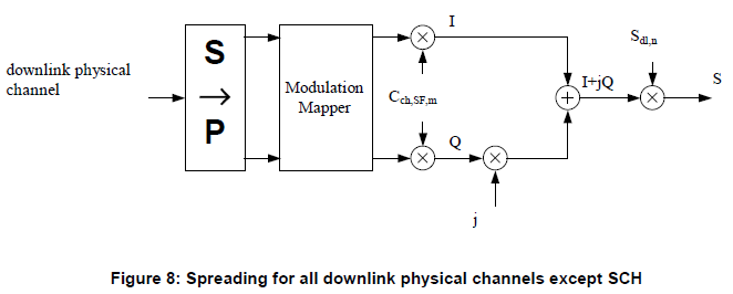
25.213 Figure 8, Spreading for all downlink physical channels except SCH. The channel is modulated and spread first, and the complex result is multiplied by the downlink scrambling code Sdl,n.
S to P and Modulation Mapper : the physical channel is split into pairs of bits and mapped to an I branch and a Q branch.Cch,SF,m : both branches are spread by the same channelisation code, the OVSF code m at spreading factor SF.Sdl,n : the combined I+jQ signal is multiplied by the downlink scrambling code n.Except SCH : the synchronisation channel is not scrambled, because the UE has to find it before it knows any scrambling code.
For the details of DL channels of scrambling code, refer to 25.213, section 5.1.4 Scrambling
Decoded RRC message from a tester log,
DL-CCCH-Message ::= SEQUENCE [0]
  +-integrityCheckInfo ::= SEQUENCE OPTIONAL:Omit
  +-message ::= CHOICE [rrcConnectionSetup]
    +-rrcConnectionSetup ::= CHOICE [r3]
      +-r3 ::= SEQUENCE [0]
        +-rrcConnectionSetup-r3 ::= SEQUENCE [0011100111]
        |
        | +-dl-InformationPerRL-List ::= SEQUENCE OF SIZE(1..maxRL[8]) [1] OPTIONAL:Exist
        |   +-DL-InformationPerRL ::= SEQUENCE [10]
        |     +-modeSpecificInfo ::= CHOICE [fdd]
        |     | +-fdd ::= SEQUENCE [00]
        |     |   +-primaryCPICH-Info ::= SEQUENCE
        |     |   | +-primaryScramblingCode ::= INTEGER (0..511) [9]
        |     |   +-dummy1 ::= SEQUENCE OPTIONAL:Omit
        |     |   +-dummy2 ::= SEQUENCE OPTIONAL:Omit
        |     +-dl-DPCH-InfoPerRL ::= CHOICE [fdd] OPTIONAL:Exist
        |     | +-fdd ::= SEQUENCE [000]
        |     |   +-pCPICH-UsageForChannelEst ::= ENUMERATED [mayBeUsed]
        |     |   +-dpch-FrameOffset ::= INTEGER (0..149) [0]
        |     |   +-secondaryCPICH-Info ::= SEQUENCE OPTIONAL:Omit
        |     |   +-dl-ChannelisationCodeList ::= SEQUENCE OF SIZE(1..maxDPCH-DLchan[8]) [1]
        |     |   | +-DL-ChannelisationCode ::= SEQUENCE [00]
        |     |   |   +-secondaryScramblingCode ::= INTEGER OPTIONAL:Omit
        |     |   |   +-sf-AndCodeNumber ::= CHOICE [sf128]
        |     |   |   | +-sf128 ::= INTEGER (0..127) [30]
        |     |   |   +-scramblingCodeChange ::= ENUMERATED OPTIONAL:Omit
        |     |   +-tpc-CombinationIndex ::= INTEGER (0..5) [0]
        |     |   +-dummy ::= ENUMERATED OPTIONAL:Omit
        |     |   +-closedLoopTimingAdjMode ::= ENUMERATED OPTIONAL:Omit
        |     +-dummy ::= SEQUENCE OPTIONAL:Omit
        +-laterNonCriticalExtensions ::= SEQUENCE OPTIONAL:Omit
Decoded RRC message from a tester log,
RRC:DL-DCCH-Message
DL-DCCH-Message ::= SEQUENCE [0]
  +-integrityCheckInfo ::= SEQUENCE OPTIONAL:Omit
  +-message ::= CHOICE [radioBearerSetup]
    +-radioBearerSetup ::= CHOICE [r3]
      +-r3 ::= SEQUENCE [0]
        +-radioBearerSetup-r3 ::= SEQUENCE [001001000100101010100111]
        |
        | +-dl-InformationPerRL-List ::= SEQUENCE OF SIZE(1..maxRL[8]) [1] OPTIONAL:Exist
        |   +-DL-InformationPerRL ::= SEQUENCE [10]
        |     +-modeSpecificInfo ::= CHOICE [fdd]
        |     | +-fdd ::= SEQUENCE [00]
        |     |   +-primaryCPICH-Info ::= SEQUENCE
        |     |   | +-primaryScramblingCode ::= INTEGER (0..511) [9]
        |     |   +-dummy1 ::= SEQUENCE OPTIONAL:Omit
        |     |   +-dummy2 ::= SEQUENCE OPTIONAL:Omit
        |     +-dl-DPCH-InfoPerRL ::= CHOICE [fdd] OPTIONAL:Exist
        |     | +-fdd ::= SEQUENCE [000]
        |     |   +-pCPICH-UsageForChannelEst ::= ENUMERATED [mayBeUsed]
        |     |   +-dpch-FrameOffset ::= INTEGER (0..149) [0]
        |     |   +-secondaryCPICH-Info ::= SEQUENCE OPTIONAL:Omit
        |     |   +-dl-ChannelisationCodeList ::= SEQUENCE OF SIZE(1..maxDPCH-DLchan[8]) [1]
        |     |   | +-DL-ChannelisationCode ::= SEQUENCE [00]
        |     |   |   +-secondaryScramblingCode ::= INTEGER OPTIONAL:Omit
        |     |   |   +-sf-AndCodeNumber ::= CHOICE [sf128]
        |     |   |   | +-sf128 ::= INTEGER (0..127) [5]
        |     |   |   +-scramblingCodeChange ::= ENUMERATED OPTIONAL:Omit
        |     |   +-tpc-CombinationIndex ::= INTEGER (0..5) [0]
        |     |   +-dummy ::= ENUMERATED OPTIONAL:Omit
        |     |   +-closedLoopTimingAdjMode ::= ENUMERATED OPTIONAL:Omit
        |     +-dummy ::= SEQUENCE OPTIONAL:Omit
In both captures, primaryScramblingCode in primaryCPICH-Info is 9. This is the index i of the primary code, not the code number itself, so the cell uses downlink scrambling code 16 x 9 = 144. The field secondaryScramblingCode is omitted in both captures, so the dedicated channel uses the primary scrambling code of the cell. Inside dl-InformationPerRL, the only value that differs is the channelisation code: sf128 code 30 in the RRC Connection Setup and sf128 code 5 in the Radio Bearer Setup.
25.213 subclause 5.2.2 also sets which channels must use the primary code. The P-CCPCH, the P-CPICH, the PICH, the MICH, the AICH and an S-CCPCH carrying PCH or BCH always use the primary scrambling code. Other downlink channels may use the primary code or one secondary code from the set of the cell. The listing below shows the related IEs in the current 25.331.
Following is based on
PrimaryCPICH-Info ::=				SEQUENCE {
	primaryScramblingCode				PrimaryScramblingCode
}

PrimaryScramblingCode ::=			INTEGER (0..511)

SecondaryScramblingCode ::=			INTEGER (1..15)
SecondaryScramblingCode runs from 1 to 15, and the value 0 does not exist. The value 0 would be the primary code itself, and the primary code is signalled by leaving the field out.
primaryScramblingCode is an index : the code number is 16 times the signalled value, so 9 means code 144.An omitted secondaryScramblingCode means the primary code : the value range 1 to 15 counts only the secondary codes of the set.Common channels always use the primary code : only dedicated and some shared channels can move to a secondary code.
Reference
- 3GPP TS 25.213 : Spreading and modulation (FDD), v19.0.0. Subclauses 4.3.2, 4.3.3, 5.1.4 and 5.2.2; Figures 1, 2 and 8.
- 3GPP TS 25.331 : Radio Resource Control (RRC); Protocol specification, v19.0.1. ASN.1 of PreambleScramblingCodeWordNumber, UL-ScramblingCode, ScramblingCodeType, PrimaryCPICH-Info, PrimaryScramblingCode and SecondaryScramblingCode.