USSD is a kind of protocol (Supplementary Service protocol) that is designed for a UE to communicate with the service provider's computer. It was originally designed for GSM cellular communication and now is being used in WCDMA network as well.
In terms of base protocol, it is very similar to SMS. Like SMS, it is using control channel to carry the data. In WCDMA, it use DCCH to carry the data and in GSM it use SDCCH to carry the data.
However, there is minor difference in terms of managing a session. (According to Wikipedia )Unlike Short Message Service (SMS) messages, USSD messages create a real-time connection during a USSD session. The connection remains open, allowing a two-way exchange of a sequence of data. This makes USSD more responsive than services that use SMS.
This page looks at USSD at the message level. It starts with the three SS messages and the operations inside them. Then it reads two tester captures of a network initiated USSD notification, one during a voice call and one from idle mode. It ends with the rules for sending more than one USSD string, which answer the question the page raises there.
- Which messages and operations carry a USSD string ?
- Example 1 : MT USSD during Voice Call
- Example 2 : MT USSD during Idle - Notify
- Consecutive USSD Message
- On-line tool for decoding/ecoding USSD text with GSM 7 Bit
- Reference
Which messages and operations carry a USSD string ?
SMS has its own relay protocol, but USSD does not. It reuses the call independent supplementary service protocol of 24.080, so the same three NAS messages carry every USSD exchange. The USSD text sits inside a component, and the component names the operation.
24.080 Table 2.1 lists the three messages. REGISTER opens a new transaction. FACILITY carries a component inside a transaction that already exists. RELEASE COMPLETE clears the transaction, and it can carry a last component too. All three use the protocol discriminator 1011, supplementary services (call independent). So a decoder shows the first octet as 0x0b or 0x8b, depending on the TI flag.
The Facility IE holds the component. 24.080 Table 3.7 defines four component types. Invoke has the tag 0xa1, Return Result 0xa2, Return Error 0xa3 and Reject 0xa4. An Invoke carries an invoke ID, an operation code and the argument of the operation. The answer to that Invoke uses the same invoke ID, so the receiver can match the two.
Three operations do the USSD work. The table below lists them with the direction that 24.080 subclause 4.2.2 gives them.
Operation |
Direction |
Purpose |
processUnstructuredSS-Request |
MS to network |
The MS starts a USSD application in the network, for example after the user dials a USSD code. |
unstructuredSS-Request |
network to MS |
The network asks the user for input and expects the answer in a Return Result. |
unstructuredSS-Notify |
network to MS |
The network shows a text to the user and expects only an empty Return Result. |
Each of these operations carries two fields, ussd-DataCodingScheme and ussd-String. The coding scheme uses the CBS Data Coding Scheme of 23.038 clause 5. With the GSM 7 bit default alphabet, one USSD message can hold up to 182 user characters. The 7-bit characters are packed into octets in the same way as for SMS.
The transaction rules matter as much as the messages. 24.090 allows only one USSD transaction per user at a time among the call independent SS transactions. But a USSD transaction may run in parallel with a call related transaction, such as a voice call. Example 1 below is exactly this case, and the Consecutive USSD Message section comes back to the rule.
Three SS messages carry every USSD exchange : REGISTER opens the transaction, FACILITY continues it and RELEASE COMPLETE clears it.The component says what the message means : the same FACILITY message can carry an Invoke, a Return Result, a Return Error or a Reject.The operation tells MO from MT : processUnstructuredSS-Request comes from the MS, while unstructuredSS-Request and unstructuredSS-Notify come from the network.
Example 1 : MT USSD during Voice Call
This example shows a case that 24.090 allows explicitly. The network starts a USSD operation while a call related transaction is running. The UE first sets up an MO voice call, and the network then sends a USSD notification over the same RRC connection.
1) RRC : RRC Connection Request
2) RRC : RRC Connection Setup
3) RRC : RRC Connection Setup Complete
4) RRC: initialDirectTransfer + MM : CM Service Request
5) RRC : downlinkDirectTransfer + MM:Authentication Request
6) RRC : uplinkDirectTransfer + MM:Authentication Response
7) RRC : Security Mode Command
8) RRC : Security Mode Complete
9) RRC : uplinkDirectTransfer + CC : Setup
10) RRC : downlinkDirectTransfer + CC : Call Proceeding
11) RRC : Radio Bearer Setup
12) RRC : Radio Bearer Setup Complete
13) RRC : downlinkDirectTransfer + CC : Alerting
14) RRC : uplinkDirectTransfer + CC : Connect
15) RRC : downlinkDirectTransfer + CC : Connect Acknowledge
16) < Voice Traffic >
17) NW --> UE : SS : Register (USSD : send 'Register')
18) NW <-- UE : SS : Facility (USSD : recieve 'Facility')
19) NW --> UE : SS : Release Complete (USSD : send 'Release Complete')
Steps 1 to 15 are an ordinary MO voice call setup, and step 16 is the voice traffic. The USSD exchange is steps 17 to 19, and it follows 24.090 Figure 5.3, a single network initiated USSD notification. The words send and recieve in the list are from the tester side, so send means that the network sends the message.
No new RRC connection and no new security procedure are needed. The SS messages travel on the existing DCCH inside downlinkDirectTransfer and uplinkDirectTransfer, with the CS domain as the CN domain. They open their own SS transaction, which is separate from the CC transaction of the call.
Example Contents of Step 17
The network opens the USSD transaction with REGISTER. The RRC layer only carries it. The downlinkDirectTransfer names the CS domain and holds the NAS octets in nas-Message, and the decoder then expands those octets as a DTAP message.
Decoded DL-DCCH downlinkDirectTransfer carrying the SS REGISTER message,
    DL-DCCH-Message
    message: downlinkDirectTransfer (5)
        downlinkDirectTransfer: r3 (0)
            r3
                downlinkDirectTransfer-r3
                    rrc-TransactionIdentifier: 0
                    cn-DomainIdentity: cs-domain (0)
                    nas-Message: 0b3b1c23a12102010002013d301904010004144d2aa83a9d...
                    GSM A-I/F DTAP - Register
                        Protocol Discriminator: Non call related SS messages
                            .... 1011 = Protocol discriminator: Non call related SS messages (0x0b)
                            0... .... = TI flag: allocated by sender
                            .000 .... = TIO: 0
                        ..11 1011 = DTAP Non call Supplementary Service Message Type: Register (0x3b)
                        Facility
                            Element ID: 0x1c
                            Length: 35
                            GSM Mobile Application
                                Component: invoke (1)
                                    invoke
                                        invokeID: 0
                                        opCode: localValue (0)
                                            localValue: unstructuredSS-Notify (61)
                                        ussd-DataCodingScheme: 00
                                            0000 .... = Coding Group: Coding Group 0 - GSM 7 bit
                                            .... 0000 = Language: German (0)
                                        ussd-String: 4d2aa83a9d12413ad0d35e96838653d030cc6603
                                        USSD String: MT USSD : Over CS Call
Let's read the start of nas-Message against the decode. The octets split into the following fields.
- 0b : protocol discriminator 1011 with TI flag 0 and TIO 0, so the network allocated this TI
- 3b : message type REGISTER
- 1c 23 : Facility IE, 35 octets long
- a1 21 : Invoke component, 33 octets long
- 02 01 00 : invoke ID 0
- 02 01 3d : operation code 61, unstructuredSS-Notify
- 30 19 : the argument, a SEQUENCE of 25 octets
- 04 01 00 : ussd-DataCodingScheme 0x00
- 04 14 ... : ussd-String, 20 octets
The decoder cuts the nas-Message line after 4d2aa83a9d, but the ussd-String line shows all 20 octets. 20 octets hold 160 bits. That is 22 characters of 7 bits, with 6 bits of padding, and it matches the 22 characters of MT USSD : Over CS Call.
The coding scheme 0x00 is coding group 0000 with language 0000. In 23.038 clause 5 this means German, written in the GSM 7 bit default alphabet. The text itself is English, so the language bits do not describe this text. Decoding depends only on the alphabet, so the string is still decoded correctly.
Example Contents of Step 18
The UE answers the notification inside the same transaction. 24.090 subclause 5.2.1 asks for a FACILITY message with an empty result component, and this is what the capture shows.
Decoded UL-DCCH uplinkDirectTransfer carrying the SS FACILITY message,
    UL-DCCH-Message
    message: uplinkDirectTransfer (27)
        uplinkDirectTransfer
            cn-DomainIdentity: cs-domain (0)
            nas-Message: 8b3a05a203020100
            GSM A-I/F DTAP - Facility
                Protocol Discriminator: Non call related SS messages
                    .... 1011 = Protocol discriminator: Non call related SS messages (0x0b)
                    1... .... = TI flag: allocated by receiver
                    .000 .... = TIO: 0
                ..11 1010 = DTAP Non call Supplementary Service Message Type: Facility (0x3a)
                Facility
                    Length: 5
                    GSM Mobile Application
                        Component: returnResultLast (2)
                            returnResultLast
                                invokeID: 0
The nas-Message is only 8 octets long. The first octet is 0x8b, because the UE sets the TI flag to 1 for a TI that the other side allocated. Message type 0x3a is FACILITY. In FACILITY the Facility IE is mandatory, so it has no IEI and starts directly with its length, 05. The component a2 03 02 01 00 is a Return Result with invoke ID 0 and no result data. Invoke ID 0 ties it to the Invoke of step 17.
Example Contents of Step 19
The network ends the USSD dialogue with RELEASE COMPLETE. This clears only the SS transaction. The voice call and the RRC connection stay up, because the CC transaction still uses them.
Decoded DL-DCCH downlinkDirectTransfer carrying the SS RELEASE COMPLETE message,
    DL-DCCH-Message
    integrityCheckInfo
    message: downlinkDirectTransfer (5)
        downlinkDirectTransfer: r3 (0)
            r3
                downlinkDirectTransfer-r3
                    rrc-TransactionIdentifier: 0
                    cn-DomainIdentity: cs-domain (0)
                    nas-Message: 0b2a1c05a203020100
                    GSM A-I/F DTAP - Release Complete
                        Protocol Discriminator: Non call related SS messages
                            .... 1011 = Protocol discriminator: Non call related SS messages (0x0b)
                            0... .... = TI flag: allocated by sender
                            .000 .... = TIO: 0
                        ..10 1010 = DTAP Non call Supplementary Service Message Type:
                                                          Release Complete (0x2a)
                        Facility
                            Element ID: 0x1c
                            Length: 5
                            GSM Mobile Application
                                Component: returnResultLast (2)
                                    returnResultLast
                                        invokeID: 0
Message type 0x2a is RELEASE COMPLETE, and the TI flag is 0 again because the network sends it. The decoder splits the message type line in two, and the second line holds the name. The message also carries a Facility IE with a Return Result for invoke ID 0.
That component is more than 24.090 asks for. For a network initiated notification, subclause 5.2.1 only says that the network clears the transaction with RELEASE COMPLETE. A Return Result inside RELEASE COMPLETE belongs to the mobile initiated case of subclause 6.1, where the network answers the processUnstructuredSS-Request of the MS. The capture is shown as the tester sent it.
USSD during a call reuses the call connection : the SS messages go on the existing DCCH, with no paging, no new RRC connection and no new security procedure.The TI flag shows who opened the transaction : the network messages carry flag 0 and the UE answer carries flag 1.A notification needs only an empty result : the UE answers unstructuredSS-Notify with a FACILITY that holds a Return Result and no data.
Example 2 : MT USSD during Idle - Notify
Without a call, the UE has no RRC connection when the notification arrives. So the network must page the UE first, and the USSD exchange starts only after the RRC connection and the security setup.
1) Paging Type 1
2) RRC : RRC Connection Request
2) RRC : RRC Connection Setup
3) RRC : RRC Connection Setup Complete
4) RRC: initialDirectTransfer + RR : Paging Response
5) RRC : downlinkDirectTransfer + MM:Authentication Request
6) RRC : uplinkDirectTransfer + MM:Authentication Response
7) RRC : Security Mode Command
8) RRC : Security Mode Complete
9) SS : Register (USSD : send 'Register')
10) SS : Facility (USSD : recieve 'Facility')
11) SS : Release Complete (USSD : send 'Release Complete')
12) RRC : RRC Connection Release
13) RRC : RRC Connection Release Complete
Two things differ from Example 1. The first is that the UE answers a page, so its first NAS message is a PAGING RESPONSE and not a CM SERVICE REQUEST. 24.008 subclause 4.5.1.3.3 has the MS respond to paging in Iu mode with the PAGING RESPONSE of 44.018, and the message keeps the RR protocol discriminator. The second is that nothing else uses the connection. So after RELEASE COMPLETE, the network releases the RRC connection in steps 12 and 13.
Steps 9 to 11 are the same three SS messages as steps 17 to 19 of Example 1. Only the first step is captured here, because the page is what makes this example different.
Example Contents of Step 1
The page is a Paging Type 1 on the PCCH, because the UE is in idle mode. The paging record tells the UE which core network domain pages it, with which identity, and for what reason.
Decoded PCCH Paging Type 1 for the MT USSD,
    PCCH-Message
    message: pagingType1 (0)
        pagingType1
            pagingRecordList: 1 item
                Item 0
                    PagingRecord: cn-Identity (0)
                        cn-Identity
                            pagingCause: terminatingHighPrioritySignalling (4)
                            cn-DomainIdentity: cs-domain (0)
                            cn-pagedUE-Identity: tmsi-GSM-MAP (1)
                                tmsi-GSM-MAP: 00000001
The CS domain pages the UE with its TMSI, tmsi-GSM-MAP 00000001. The pagingCause is terminatingHighPrioritySignalling. A USSD notification is signalling rather than a call, so the core network does not use a call related cause such as terminatingConversationalCall. The RRC layer of the UE forwards the paging cause to the upper layers, as 25.331 subclause 8.1.2 describes.
An idle UE is paged first : the CS domain pages it on the PCCH with a signalling cause.The first NAS message is PAGING RESPONSE : the UE answers the page, so it does not send a CM SERVICE REQUEST.The connection ends with the USSD dialogue : with no call running, the network releases the RRC connection after RELEASE COMPLETE.
Consecutive USSD Message
One USSD string per transaction is the simple case. A service menu often needs several strings in a row, and the network can order them in more than one way. The transaction rule of 24.090 decides which order the UE accepts.
Normally we send or receive one USSD message in one RRC session, but there case be a case where UE or NW want to send multiple USSDs consecutively. We can think of following two cases for this consecutive USSD.
Case 1
In this case the network closes the first USSD transaction with RELEASE COMPLETE before it sends the second REGISTER. So at any moment only one call independent SS transaction exists.
1) < Make a call (CS or PS) >
2) SS : Register (USSD : send 'Register') - First USSD String
3) SS : Facility (USSD : recieve 'Facility')
4) SS : Release Complete (USSD : send 'Release Complete')
5) SS : Register (USSD : send 'Register') - Second USSD String
6) SS : Facility (USSD : recieve 'Facility')
7) SS : Release Complete (USSD : send 'Release Complete')
Case 2
In this case the network sends a second REGISTER while the first transaction is still open. The second REGISTER starts a new transaction, so for a short time two call independent SS transactions exist at once.
1) < Make a call (CS or PS) >
2) SS : Register (USSD : send 'Register') - First USSD String
3) SS : Facility (USSD : recieve 'Facility')
4) SS : Register (USSD : send 'Register') - Second USSD String
5) SS : Facility (USSD : recieve 'Facility')
6) SS : Release Complete (USSD : send 'Release Complete')
Somehow when I tested these two cases with some of commerical UE, < Case 2 > work as expected but < Case 1 > does not work as expected. UE send 'Release Complete with 'ussd-busy' error at step 6). I am not sure yet.. if this is because 3GPP spec does not allow it or any UE issues. In terms of 3GPP spec, I see conflicting statements as follows. It will be appreciated if any expert in this area provide some advice on this.
TS 24.080 4.3.2.22 ussd-Busy
This error is returned by the MS to the network when the MS is not able to process the unstructured supplementary service data operation due to an on-going MMI input of the user or an already existing call independent supplementary service transaction.
TS 24.090 5.1.1 Normal Operation
When the MS receives an USSD operation in parallel to any call independent supplementary service transaction, it shall respond with a return error component in a RELEASE COMPLETE message, containing the "USSD-Busy" error as specified in 3GPP TS 24.080, to indicate the failure in handling a parallel USSD operation. However, the network is allowed to initiated USSD operations in parallel to call related transactions.
Which case does the specification allow ?
The two quoted rules do not conflict. They describe the same restriction from two sides. 24.080 defines what ussd-Busy means, and 24.090 says when the MS must return it.
The restriction covers call independent SS transactions only. A voice call or a PS session is not one of them, so the call in step 1 of both cases never causes ussd-Busy. The last sentence of the 24.090 quote says this: the network may start USSD operations in parallel to call related transactions.
Case 1 keeps only one SS transaction at a time. The first transaction is cleared at step 4, before the second REGISTER arrives at step 5. So 24.090 gives the MS no reason to reject the second string.
Case 2 opens a second transaction while the first is still active. This is exactly the condition in 24.090 subclause 5.1.1: the MS receives a USSD operation in parallel to a call independent SS transaction. So the MS must answer with a RELEASE COMPLETE that carries a return error with ussd-Busy. A UE that rejects Case 2 in this way follows the specification.
The test result above says the opposite, with Case 1 failing at step 6. But step 6 of Case 2 is the RELEASE COMPLETE, where a ussd-Busy rejection would appear, while step 6 of Case 1 is a FACILITY. So the two case names in the result may have been swapped when the result was written down.
24.090 also shows the clean way to send several strings. In Figure 5.2, the network keeps one transaction open and sends the next unstructuredSS-Request or unstructuredSS-Notify in a FACILITY message. Only the final message is a RELEASE COMPLETE. This avoids the parallel transaction completely.
One USSD transaction at a time : the MS rejects a second call independent SS transaction with ussd-Busy in RELEASE COMPLETE.Calls do not count : USSD may run in parallel to a CS call or a PS session.Continue with FACILITY : the safe way to send more strings is inside the open transaction, as in 24.090 Figure 5.2.
On-line tool for decoding/ecoding USSD text with GSM 7 Bit
USSD text in the GSM 7 bit default alphabet is packed, so the hex string in a log cannot be read directly. An encoder saves the manual bit work when you build a test string or check a capture.
When you want to encode USSD Hex string from a text string, I would recommend you to try with the following tool from http://smstools3.kekekasvi.com/topic.php?id=288
The screenshot below shows that tool with the text of Example 1, MT USSD : Over CS Call. The Text box counts 22 of 160 characters. The USSD Entry/Display box is set to GSM 7bit packed, and it shows the packed result 4D2AA83A9D12413AD0D35E96838653D030CC6603. The PDU Message box above it holds the same text inside a complete SMS PDU.
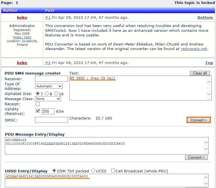
The packed string is identical to the ussd-String of Example 1, step 17, so the tool reproduces what the network sent.
The packing is simple enough to check by hand. 23.038 clause 6.1.2.3 packs USSD in the same way as SMS. Each character has 7 bits, and the next character fills the free high bits of the current octet.
- The first character M is 0x4D. The lowest bit of the second character T, 0x54, is 0, so the first octet is 0x4D.
- The remaining 6 bits of T, 0x2A, and the lowest 2 bits of the space character, 0x20, give the second octet 0x2A.
- The same shift continues for all 22 characters, and the last 6 bits are set to zero.
23.038 adds one special rule for USSD. When the number of characters is 8n - 1, the last octet has 7 spare bits. A receiver could read 7 zero bits as the @ character, which is 0x00 in the default alphabet. So the sender uses a carriage return as the padding in that case, and the receiver removes a final carriage return that ends on an octet boundary.
8 characters fit in 7 octets : GSM 7 bit packing puts 182 characters into the 160 octets of the longest USSD string.A carriage return can be padding : it fills 7 spare bits so that they are not read as @.
Reference
- 3GPP TS 24.080 v19.3.0 : Mobile radio interface layer 3 supplementary services specification; Formats and coding
- 3GPP TS 24.090 v19.0.0 : Unstructured Supplementary Service Data (USSD); Stage 3
- 3GPP TS 23.038 v20.0.0 : Alphabets and language-specific information
- 3GPP TS 24.008 v20.0.0 : Mobile radio interface Layer 3 specification; Core network protocols; Stage 3, subclause 4.5.1.3.3
- 3GPP TS 25.331 v19.0.1 : Radio Resource Control (RRC); Protocol specification, subclause 8.1.2