These snapshot is for Uplink only. No Downlink is shown here. A WCDMA UE changes its transmit power many times between power on and a voice call. Each phase of the call setup uses a different channel and a different rule for setting the power. So a Power vs Time plot shows you which phase the UE is in, even without a protocol log. The five snapshots below follow one UE through registration and a voice call, and each section explains which rule sets the power in that phase.
- What does each Power vs Time screen show ?
- Step 1 - Initial RACH after power on
- Step 2 - Power control during registration
- Step 3 - End of registration
- Step 4 - RACH for a mobile originated call
- Step 5 - Power during a voice call
- What sets the UE power in each phase ?
- Reference
What does each Power vs Time screen show ?
All five snapshots come from the same kind of analyzer screen, so let's go through its layout once before the steps. The numbers on the screen are easy to misread if you do not know which trace they belong to.
Each screen has two traces. The upper trace is a zoomed window, and its start and length are shown at the top right as Analysis Start Time and Analysis Time Length. The window is 50 ms long in most snapshots, so one horizontal division is 5 ms. The lower trace shows the whole capture, from 18 ms to about 4.98 s, and a blue box marks where the zoomed window sits in it. The vertical axis is in dBm, 10 dB per division. Detection is average, with no filter, over 10001 trace points. For a 50 ms window that is one point every 5 microseconds, which is fine enough to see single slots.
The flat line at about -71 dBm is the analyzer noise floor. It means that the UE transmitter is off. 25.101 requires the transmit OFF power to be below -56 dBm, and the minimum output power while the UE transmits to be below -50 dBm. So any level near -71 dBm in these plots is simply "no transmission". The two markers, MKR 1 and MKR 2, give time and power at two points, and the third line gives the difference between them.
The upper trace is the zoom, the lower trace is the map : Check the blue box in the lower trace to see where in the call setup a snapshot was taken.-71 dBm is the floor, not a power level : The UE is not transmitting in those parts of the trace.One division is 5 ms in a 50 ms window : Use this to estimate slot counts and gaps, but note that Step 3 uses a 215 ms window.
Step 1 - Initial RACH after power on
When you turn on the power, if UE properly detected a cell and the cell is 'suitable cell', UE initial RACH procedure as shown below.
The UE has no dedicated channel yet, and the network has not heard it before. So the UE has to guess its first power from its own downlink measurement, and it then raises the power until the NodeB answers. That is the preamble ramping of the PRACH, and at power on its message usually carries the RRC CONNECTION REQUEST for the registration.
In the snapshot below, the window runs from 90.2 ms to 140.2 ms. Two short RACH Preambles appear at about -48 dBm, a few milliseconds apart. A much longer RACH Message follows at about -43 dBm, and then the UE switches off again. The lower trace shows that the UE starts a long transmission shortly after this window.
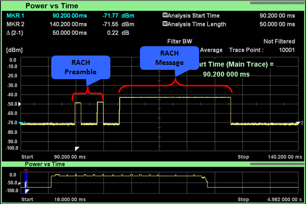
The first preamble gets no answer, the second is acknowledged, and the message follows at a higher power.
RACH Preamble : Each preamble is 4096 chips, about 1.07 ms. The UE sends the next preamble only when it detects no acquisition indicator on the AICH, so the first preamble here was not acknowledged.Preamble power : The first preamble uses Preamble_Initial_Power = Primary CPICH TX power - CPICH_RSCP + UL interference + Constant Value. Each new preamble is raised by Power Ramp Step. At 10 dB per division, a step of 1 or 2 dB is hard to see, so the two preambles look equal.Gap to the message : The message starts about 4 ms after the start of the last preamble. 25.214 puts it three or four access slots after the last preamble, depending on AICH_Transmission_Timing. An access slot is 5120 chips, about 1.33 ms, so 4 ms is three access slots.RACH Message : The message lasts about 20 ms, which matches the 20 ms message length option. Its control part is set Pp-m dB relative to the last preamble, and the data part adds its own power on top. That is why the message is about 5 dB above the preambles.
Step 2 - Power control during registration
Once RACH process is complete, UE and NodeB exchanges signaling message for registration. During this period, you may some power changes based on TPC commands from NodeB but this TPC process is not necessarily happen everytime.
From here on, the UE has a dedicated physical channel, and the NodeB controls the power slot by slot. The question is where the UE starts before any TPC command arrives. 25.331 gives an open loop answer, DPCCH_Initial_power = DPCCH_Power_offset - CPICH_RSCP, where the network sends DPCCH_Power_offset in the Uplink DPCH power control info.
In the snapshot below, the window runs from 555.7 ms to 605.7 ms. The UE is off at the start, then jumps to about -25 dBm. Within about 5 ms the power climbs to about -18 dBm, and then it stays there with small steps. The red bracket marks this climb as the ramp caused by power control.
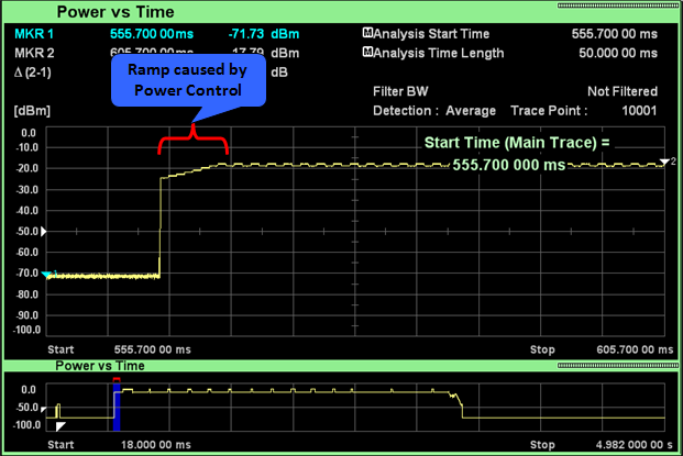
The UE starts the dedicated channel at an open loop estimate, and the inner loop power control then corrects it within a few slots.
The jump : This is most likely the start of the uplink DPCCH after the RRC CONNECTION SETUP moved the UE to CELL_DCH. The level of the jump is DPCCH_Initial_power plus the gain of any other channel sent with it.The ramp : The NodeB compares the received SIR with its target and sends one TPC command per slot. A slot is 0.667 ms, and the step size is 1 dB or 2 dB. A climb of about 7 dB in about 5 ms fits a run of 1 dB up commands.The flat part : After the ramp the SIR is close to the target, so the TPC commands alternate between up and down. That produces the small steps along the top of the trace.Power control preamble : 25.214 lets the network configure Npcp radio frames of DPCCH only before the DPDCH starts, so the first frames may carry no data at all.
Step 3 - End of registration
Following shows the power profile changes around the end of registration. At the end of the registration, the network releases the RRC connection, and the UE goes back to idle mode. So the dedicated channel stops, and the UE transmitter turns off. The interesting part is what the power does just before that.
This snapshot uses a longer window of 215 ms, from 3.1868 s to 3.4018 s. The power first stays near -18 dBm. It then falls with some ripples for about 150 ms to about -45 dBm. Finally the UE switches off in a single step. MKR 1 reads -18.96 dBm and MKR 2 reads -71.59 dBm, a difference of -52.63 dB.
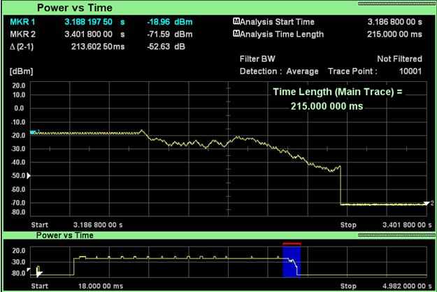
The power control stays active until the last slot, and the transmitter then switches off at once.
The fall is closed loop power control : The UE follows the TPC commands to the end. The trace alone does not show which commands the NodeB sent, so it does not show why the power fell.The switch off : In CELL_DCH the UE sends the RRC CONNECTION RELEASE COMPLETE in unacknowledged mode. It repeats the message when T308 expires, up to N308 times, and then enters idle mode. The transmitter turns off at that point.The lower trace : The blue box sits at the end of the long transmission that started after Step 1. So this whole block is one RRC connection, used for the registration.
Step 4 - RACH for a mobile originated call
If you make a call in the idle mode, you would see RACH power as you saw in step 1. After the registration, the UE is in idle mode again, with no dedicated channel. So a new call starts with the same random access procedure as in Step 1. This time the RRC CONNECTION REQUEST carries an establishment cause for an originating call instead of a registration.
In the snapshot below, the window runs from 83 ms to 133 ms of this capture. Two RACH Preambles appear at about -48 dBm, and the RACH Message follows at about -43 dBm and lasts about 20 ms. The lower trace shows that the UE then transmits almost to the end of the capture, which is the call.
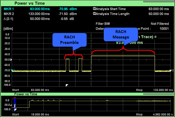
The RACH for a call looks the same as the RACH at power on, because the same open loop rule sets its power.
Same levels as Step 1 : Preamble_Initial_Power depends on the CPICH TX power, the measured CPICH_RSCP and the UL interference. In a test setup those do not change between the two captures, so the levels match.Two preambles again : The first preamble was again not acknowledged. The number of preambles depends on the NodeB and on the initial power, not on the purpose of the access.A real network differs : There the CPICH_RSCP and the interference change with the UE position and the cell load, so the RACH power of two calls can differ by many dB.
Step 5 - Power during a voice call
Following is an example of power profile during voice call. During the call, the UE stays on its dedicated channel, and the inner loop power control runs in every slot. With a fixed test setup, the received SIR stays close to the target. So the power should look almost flat, and the snapshot below confirms that.
The window runs from 4.3975 s to 4.4475 s. The power stays between about -18 dBm and -20 dBm for the whole 50 ms. MKR 1 reads -18.67 dBm and MKR 2 reads -19.47 dBm, 44.725 ms later, a difference of only -0.80 dB. The small steps along the trace are the same kind of steps as in the flat part of Step 2.
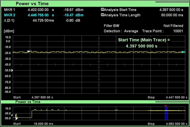
In a static channel the inner loop keeps the power within about 1 dB, so the voice call shows as a nearly flat line.
Alternating TPC commands : When the SIR sits at the target, the NodeB sends up and down commands in turn. The UE power then moves by one step size and back.The same level as the registration : The call runs at about the same power as the flat part of Step 2, because the path loss and the SIR target did not change much.A fading channel looks different : With fading, the power follows the fades and moves by many dB, as long as the UE stays below its maximum power.
What sets the UE power in each phase ?
The five steps use three different mechanisms, and it helps to see them side by side. Open loop control sets the power where the NodeB has not yet heard the UE. Closed loop control takes over once there is a dedicated channel. The RF specification sets the floor for the off periods.
Phase |
Channel |
What sets the power |
Specification |
Step 1 and Step 4, preambles |
PRACH preamble |
Open loop Preamble_Initial_Power, plus Power Ramp Step for each unanswered preamble |
25.331 8.5.7, 25.214 6.1 |
Step 1 and Step 4, message |
PRACH message |
Last preamble power plus Pp-m for the control part, and gain factors for the data part |
25.214 6.1 |
Step 2, start of the dedicated channel |
DPCCH |
Open loop DPCCH_Initial_power = DPCCH_Power_offset - CPICH_RSCP |
25.331 8.5.3 |
Step 2, Step 3 and Step 5 |
DPCCH and DPDCH |
Inner loop TPC, one command per slot, step size 1 dB or 2 dB |
25.214 5.1.2.2 |
Between the phases |
None |
Transmit OFF power below -56 dBm |
25.101 6.5.1 |
The outer loop is missing from the table because it does not act on the UE power directly. The RNC sets the SIR target from the block error rate, and the NodeB uses that target to decide its TPC commands. So a change in the outer loop shows up in these plots only as a slow drift of the closed loop level.
Open loop only at the start : The UE uses its own CPICH measurement only for the first preamble and for the first DPCCH power.Closed loop everywhere else : On a dedicated channel, every change you see in the trace is the result of TPC commands.The floor is the analyzer, not the UE : The UE only has to stay below -56 dBm when it is off, and the analyzer shows about -71 dBm.
Reference
- 3GPP TS 25.214 v19.0.0 : Physical layer procedures (FDD)
- 3GPP TS 25.211 v19.0.0 : Physical channels and mapping of transport channels onto physical channels (FDD)
- 3GPP TS 25.331 v19.0.1 : Radio Resource Control (RRC); Protocol specification
- 3GPP TS 25.101 v19.0.0 : User Equipment (UE) radio transmission and reception (FDD)