IMS  


Overall Datapath

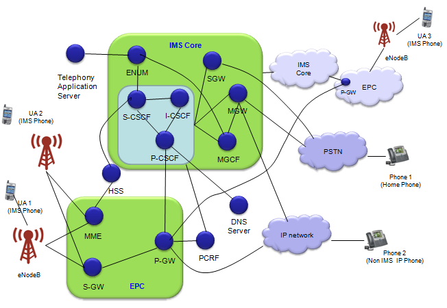
In the world of communication technologies, which keeps changing, the Session Initiation Protocol (SIP) has become very important for starting, keeping, and ending real-time talks over the Internet. It doesn't matter if it's a simple call between two people or a group call with many people, SIP is the main method used to manage these communication sessions. Learning about how data moves in SIP helps us understand better how communication works over the Internet. It also shows us how flexible and strong SIP is in dealing with different kinds of communication situations

In this note, I will talk over the overall data path in SIP protocol in a few different angles.

Overall Data Path for IMS/SIP in LTE Network

I was sitting in a couple of IMS training course. I noticed the most common questions from both instructors and audience was "How my IMS voice/data get delivered to the other side in this and that kind of situation ?".

The answer never ends and question never stops.. easily eats up the most of training session.

It may be an important question and answer and necessary to understand the details of IMS mechanism, but not easy to come out with "Short and Clear" answer to this kind of questions because there can be so many variation in each cases.

So my intention is not to give you any single solid answer for "IMS Data Path", but to give you some guide line (or logics of thinking) on IMS data delivery.

First, I want you to get yourself familiar with the following diagram.

There are several common rules which can help you to get the answer for data path by yourself.

  • i) All LTE data and all LTE signaling message has to go through eNodeB at first step.
  • ii) All LTE data (user data) has to go through S-GW and P-GW. (Note : Both IMS Signaling or IMS Data is regarded as a user data in terms of LTE network. This is an important point that would clear a lot of confusion).
  • iii) ALL IMS Signaling Message has to go through P-CSCF
  • iv) IMS Data (e.g, Voice, Video) may not go through any CSCF.
  • v) For every IMS registration, the IMS message (registration message) go through P-CSCF and S-CSCF talk to HSS to check if the user is IMS service subscriber or not.
  • vi) When you (IMS phone, UA1) want to talk to another IMS phone (UA3), IMS core has to check if the other party (UA2) is IMS subcriber and is now registered to IMS core. It is I-CSCF's job to check all these status.  
  • vii) When you (IMS phone, UA1) want to talk to another phone, first your network should check whether the other party (phone) is IMS capable phone or a home phone or just a conventional IP phone, it is ENUM's job to check about this kind of status.
  • viii) Whenever a service is initiated (requested by a UA), CSCF would talk to PCRF if the requested service is allowed for the user.

With these rules in mind (I am pretty sure that I would have missed rules), please print out the diagram above and set a specific scenario (e.g, 'I want to make a call from UA1 to UA2' or from UA1 to UA3 etc) and draw the lines for data path. Don't worry about getting wrong.. you may be wrong in a couple of points but at least more than 70% you would be right if you apply the rule listed above.
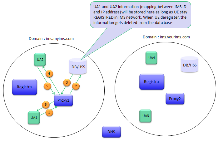
SIP Communication Path

This section will show you about overall procedure of SIP communication.

Take a look at following illustration. I put two imaginary domains and call them ims.myims.com and ims.yourims.com respectively. This illustration shows the overall registration for the case where two User Agents (UA1, UA2) are already registered in the registration system. Usually we call the registration agent in SIP communication system as Registra.

In the illustration above, we think of the case where UA1 make a call to UA2.

  • (1) UA1 make a SIP call to UA2. This Call request first reaches to the proxy (a kind of coordinator. Similar to CSCF in IMS)
  • (2) Proxy queries about the information about UA1, UA2 to the data base (HSS) which contains all the registration information and policies for all the UAs in the domain.
  • (3) Proxy recieves the informations from HSS.
  • (4) If UA2 has already been registered and policy allows the communication between UA1 and UA2. The Proxy send Alert to UA2 saying "Hey.. somebody want to talk to you !".
  • (5) If UA2 is ready to talk, it send 'Confirmation' to Proxy.
  • (6) Proxy notifies the confirmation to UA1.
  • (7) Now call setup is complete, and UA1 and UA2 talk to each other.

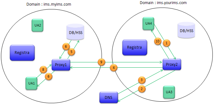
Now let's think of a little bit more complicated than previous case. As you see in the following illustration, two different domains are invovled in this example. a UA(UA4) try to make a call to a UA(UA1) which belongs to different domain.

Now let's look into each steps of communication setup.
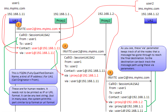
  • (1) UA4 in domain ims.yourims.com make a SIP call to UA1 in domain ims.myims.com. This Call request first reaches to the proxy. The broxy find out that the requested destination is out side of the current domain.
  • (2) The proxy (proxy2) queries DNS server to find the address of proxy of the destination domain.
  • (3) Proxy2 get the reply from DNS. Now Proxy 2 know the address of the proxy (proxy 1) in destination domain.
  • (4) Proxy2 transfer the call setup request to Proxy 1 saying "Somebody(UA4) in my domain want to talk to somebody(UA1) in your domain".
  • (5) Proxy1 queries about the information about UA1 to the data base (HSS) which contains all the registration information and policies for all the UAs in the domain.
  • (6) Proxy recieves the informations from HSS.
  • (7) If UA1 has already been registered and policy allows the communication between UA1 and UA4. The Proxy send Alert to UA1 saying "Hey.. somebody want to talk to you !".
  • (8) If UA1 is ready to talk, it send 'Confirmation' to Proxy.
  • (9) Proxy1 notifies the confirmation to Proxy2.
  • (10) Proxy2 relays the confirmation to UA4
  • (11) Now call setup is complete, and UA4 and UA1 talk to each other.

SIP Message Delivery Path

In this section, I will go over the flow of a SIP  message as it travels from the sender to the recipient through different network elements.

As an example, following diagrams outlines the path taken by a SIP INVITE message, which is used to initiate a call session in a typical Voice over IP (VoIP) setup.

The SIP INVITE message starts from User Agent 1 (UA1), which is the calling party, and travels through two proxy servers (Proxy1 and Proxy2) before reaching User Agent 2 (UA2), the called party. Along the way, the message is annotated with various headers that track its progress and provide necessary information for handling the call.

This is breakdown of this process shown above :

  • User Agent 1 (UA1) to Proxy 1:
    • The INVITE message is sent by UA1, which includes details like the Session ID, From, To, Contact, and Via header. The Via header indicates the path taken by the message (in this case, the message is initially sent from UA1's IP address).
  • Proxy 1 to Proxy 2:
    • Proxy 1 receives the INVITE message and adds its own Via header (showing Proxy1's address) before forwarding it to Proxy 2. This way, Proxy 2 knows where the message came from and how to send back the response.
  • Proxy 2 to User Agent 2 (UA2):
    • Upon receiving the INVITE message from Proxy 1, Proxy 2 adds another Via header with its own address and sends the message to UA2. This final Via header allows UA2 to understand the complete path the message has traveled


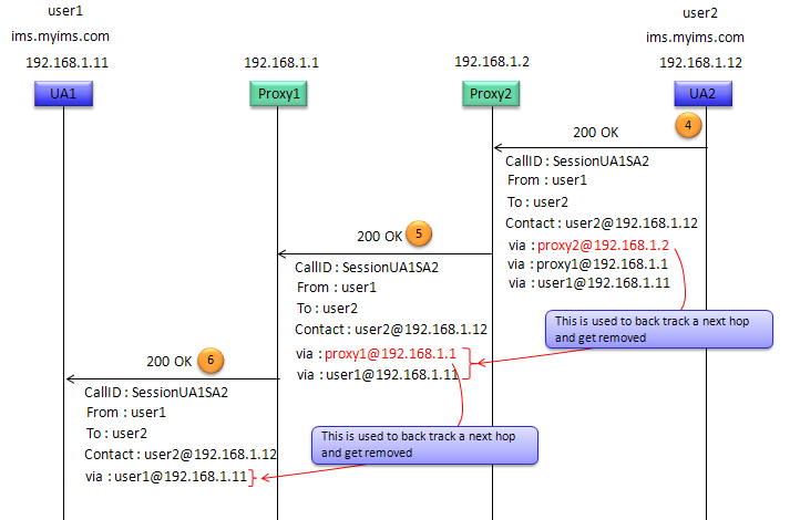
Following diagram displays the response path of a SIP message after the initial INVITE request has been made, specifically showing how the "200 OK" response travels back from the recipient to the caller.

After UA2 (User Agent 2) receives the INVITE request to start a call, it sends a "200 OK" response back to UA1 (User Agent 1) to indicate that it has successfully received the request and is ready to proceed. This response follows the reverse path through the SIP proxies that the initial INVITE request took.

This diagram emphasize that the Via headers are used to track the path taken by the SIP messages through the network. They are critical for ensuring that the response follows the exact reverse path of the request. As each node (Proxy 1 and Proxy 2) forwards the response toward UA1, it removes its Via header, thus unwinding the path the request took. When UA1 receives the "200 OK" response without any remaining Via headers, it confirms that the message has traversed back correctly through each proxy.

This is the breakdown :

  • User Agent 2 (UA2) to Proxy 2:
    • UA2 sends a "200 OK" response, which includes the same Call ID, the sender and receiver's addresses, and the contact information. The Via headers now reflect the reverse path that the response will take, starting with Proxy2's address.
  • Proxy 2 to Proxy 1:
    • Proxy 2 forwards the "200 OK" response to Proxy 1. Before forwarding, Proxy 2 removes its Via header from the response. This removal is noted in the image with the text "This is used to back track a next hop and get removed".
  • Proxy 1 to User Agent 1 (UA1):
    • Proxy 1 receives the "200 OK" response and, in turn, removes its Via header before passing the response back to UA1. This action is indicated with a similar note about backtracking the next hop and removing the header.