|
IP/Network |
||
|
VLAN
What is VLAN ? It stands for Virtual LAN. What does this mean ? VLAN stands for Virtual Local Area Network.
According to Cisco, it is defined as follows : (Refer to here for the original page) A VLAN is a group of end stations with a common set of requirements, independent of physical location. VLANs have the same attributes as a physical LAN but allow you to group end stations even if they are not located physically on the same LAN segment.
According to Techopedia, VLAN is defined as follows : (Refer to here for the original page) A virtual local area network (VLAN) is a logical group of workstations, servers and network devices that appear to be on the same LAN despite their geographical distribution. A VLAN allows a network of computers and users to communicate in a simulated environment as if they exist in a single LAN and are sharing a single broadcast and multicast domain. VLANs are implemented to achieve scalability, security and ease of network management and can quickly adapt to change in network requirements and relocation of workstations and server nodes.
When I asked about VLAN definition to chatGPT, I got following: It is a technology used to create logical networks within a physical network infrastructure. In a VLAN, a group of devices on the same physical network can be segmented into different logical networks, or subnetworks, based on their functional or security requirements VLANs are commonly used in enterprise networks to improve network performance, security, and management by separating traffic and restricting access to specific network resources. They can also be used to create guest networks, separate VoIP traffic, and segment traffic from different departments or applications.
Physical Architecture and Use case of VLAN
If you already know what VLAN is, you would understand the exact meaning of these definitions and think both of these definitions are well described. But if you are new to VLAN concept and just started studing on this, these formal definition would not give you much understanding. This is one of the biggest difficulties whenever you are trying to learn a new technology. When you need a dictionary, the dictionary would not make much sense to you. When the dictionary make sense to you, you don't need the dictionary anymore because you already knows about it :)
So, I will take a little bit different approach. Forget about the definition for now. Let's think of some of simple user case first. If you take a look at the definition after you go through followings, then the formal defintion would make sense to you.
First loot at the following setup. Five PCs are connected to a single switch and all the IPs are set to be in the same subnet. Just with basic IP knowledge, you would know that each of these PCs can talk to other PCs. For example, ping from PC (A) to all other PCs will work.
Now let's assume that the single switch is configured to have two VLAN as shown below. Don't think of what VLAN is. Don't ask how to split a single switch into multiple VLAN. Just assume that we have two VLAN as shown below. Now let's try ping test and assume that we got following result. i) Ping from A to B : OK ii) Ping from A to C : Fail iii) Ping from C to D : OK iv) Ping from C to E : OK v) Ping from C to B : Fail There are many more combination you can try, but with only this result, you would notice one important thing. The PCs that belong the same VLAN can directly talk to each other, but PCs that belong to different VLAN cannot directly talk to each other even though they are all connected to the same switch.
In other words, even though all the PCs are connected to a single switch as shown at the top of the following illustration, overall behavior of network is like as shown at the bottom of the illustration. As you see here, with VLAN you can completely separate a single network (physically same network) into multiple network (logically multiple separate networks).
Now let's think of following configuration. In this configuration, you have two switches and within each swtich there are two VLANs marked in different color (Orange : VLAN1, Red : VLAN2). You see some connection between two switches labeled as question mark. Don't ask exactly how these switches are connected. (There are several ways to implement this connection and I will explain this connection later. Just assume that this connection allows traffics among the same VLAN accorss different switches). Now let's try ping test and assume that we have following result. i) Ping from A to B : Fail ii) Ping from A to C : Fail iii) Ping from C to D : Fail iv) Ping from C to E : Fail v) Ping from D to E : OK vi) ping from A to D : OK vii) ping from D to E : OK What do you find in this test ? Again you would notice one important thing. The PCs that belong the same VLAN can directly talk to each other even when they are located in different switches. The PCs that belong to different VLAN cannot directly talk to each other even though they are connected to the same switch.
As you see here, with VLAN you can group the PCs connected to different switches so that they act as if they are connected to the same switches. Applying this logic, you can translate the physicall connection at the top of the following figure into the figure at the bottom. .
Now go back to the top of this page and see if the formal definition of VLAN make any sense to you. I hope the definition would look clearer to you.
Once you have the overall understanding on what VLAN is, you would have additiona questions right away. A couple of questions poping up in my mind are i) How a switch can figure out which VLAN each of the MAC frames should go through ? ii) How I make PCs that belong to different VLAN can talk to another PC that belong to different VLAN.
These are the topics I will explain later..
How a switch can figure out which VLAN each of the MAC frames should go through ?
How a switch (more specifically, each switch port) knows whether it should pass a certain a frame through the port or not ? There should be some indicator within the packet that gives the information for this selective passing. That specific indicator is implemented in a specific MAC frame segment called VLAN Tag as illustrated below. As you see, right after the source MAC address, there is special Type flag 0x8100 which means VLAN. After that, 4 Bytes VLAN Tag follows. The VLAN tag is made up for four fields indicating Priority, CFI, VLAN ID and ethernet type. With the VLAN ID field, each port on switch can figure out whether it has to pass through a certain frame or not.
Now the next questions is how can we connect the same VLANs physically separated by multiple switches ? In other words, how do we implement the Question mark parts in the following figure ? In this figure, PC B and C are on different switch even though they belong to a same VLAN. Also, PC A and PC D/E are connected to different switches, PC A cannot talk to PC D/E without a special connection. The question is how can we make PC A talk to PC C and PC B talk to PC D/E ? There are several ways to do it and I will introduce some of the possible solutions in this section.
The first possible solution is to connect the switches as follows. In this setup, you see extra cables and ports are used to connect the two switches and the red cable (more accurately, the switch ports to which the red cable is connected) is configured to belong to VLAN1 (VLAN Red) and the blue cable is configured to belong to VLAN 2(VLAN Orange). With this connection, if you ping from PC A to PC D, the ping start from PC A and goes through Red cable and reaches to D. If you ping from PC B to PC C, the ping start from PC B and goes through Orange cable and reaches to C. This is logically and technically simple, but as you see there is some overhead in terms of switch port usage. Since you need to allocate at least two ports and one cable for each VLAN, you would waste a lot of switch ports and cables just for connecting switches when you have many VLANs.
Isn't there any way to connect these two swiches with only one cable and two ports so that we don't have to waste too many ports and cables ? There is a way to do that using VLAN trunking. If you can configure a switch port so that it can pass through packets for multiple VLANs, you can connect the two switches with only one cable and one extra ports on each swiches. In this case, multiple VLAN packets going through the same physical medium (same ports and same cable). This kind of medium through which multiple VLAN packets can go through is called 'VLAN Trunk'. Now you may ask.. Do I need a special switch port and special cable for trunking ? Not necessarily, but in most case we use high data rate ports and cables for the trucking. It is easily understanble because this trunk should allow the throughput which is same as all the throughput of each cables.
Another way (probably the most common way) is to use router as shown below. This is a very naturable way since the main usage of a Router is to connect a network to another network. Router can connect these switches with multiple VLANs as it connect one network to another network.
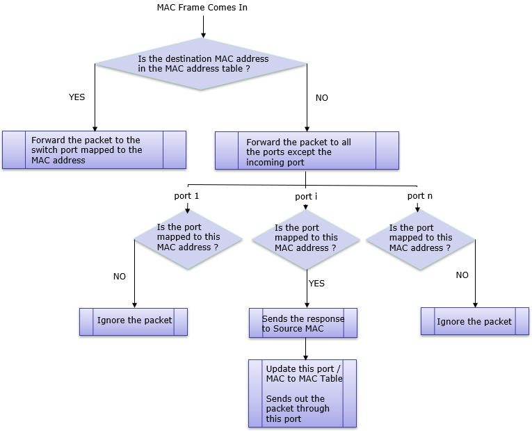
What would happen when a Packit comes into a switch port ?
When a packet comes into a switch port, a sequence of procedures would happen before it gets out of out of the switch. The procedure can be classified into roughly two cases as below.
When the incoming packet does not have VLAN information
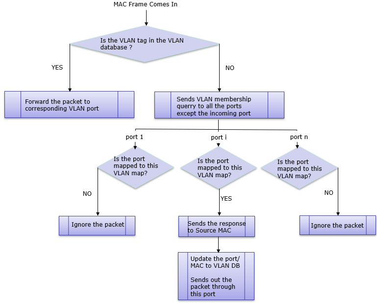
When the incoming packet has VLAN information
NOTE : If none of the port respond at this point, the packet would be discarded.
Reference
|
||