MAC
I would be almost impossible to explain everything about LTE MAC in a single column without making it a thick book or without making everybody falling in sleep since MAC is the center of all LTE procedure. You would remember that I wrote a long column for RACH procedure, but that complicated procedure is just a small portion of LTE MAC procedure.
In this column, I would focus only on MAC overview and MAC PDU structure for SCH (data transmission and reception) and the other part of the MAC will be dealt in separate columns.
Let's start with overall MAC procedure. It is always good to use an illustration/diagram to give a big picture of anything.. but ironically it would be easily overlooked if we present something in diagram. So my recommendation is to try to convert the illustration into a verbal description and to convert a verbal description into a form of illustration. At least this kind of conversion process has helped me a lot.
Let's start this conversion with the following diagram from 36.321. You may have seen this from too many different LTE training material.. and overlooked it almost every time -:).
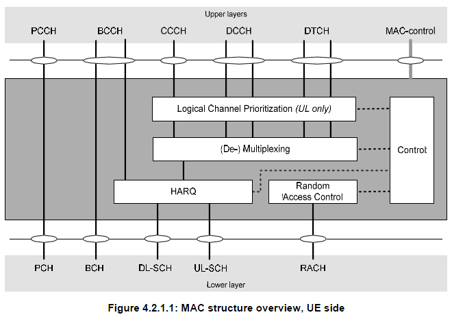
Let's just try to "read" (not "see") this illustration. I read as follows.
- i) All the logical channes (PCCH, BCCH, CCCH, DCCH, DTCH) goes through MAC layer. (too simple reading ? -:)
- ii) It seems that PCCH does not get manipulated by MAC in any special way. It just looks as if it is by passing MAC process. It does not use HARQ procedure meaning 'no retransmission' mechanism being used.
- iii) CCCH, DCCH, DTCH all go through the same procedure (Prioritization, Mux/DeMux, HARQ).
- iv) Some BCCH goes through HARQ, but some BCCH does not go through HARQ. Do you know which BCCH go through HARQ and which does not ? BCCH for MIB does not go through HARQ, but BCCH for SIB go through HARQ. (But this HARQ is a little different from normal HARQ that we know of.. It does not expecting any ACK/NACK response from the reciever.. but perform 'retransmission' based on a predefined rule).
- v) Random Access process orignated within MAC layer, it does not have the correspoding logical channel. (This may apply to Msg1, Msg2 of RACH procedure.. Msg3,4,5 involves RRC layer intervention as well).
Let's read another important illustration from 36.321. Following shows the channel mapping for various downlink data. As LTE evolves, you would see more and more new channels are added and this mapping gets more complicated. At the first stage of LTE(Rel 8), we started with "Orange colored" channels and now (Rel 13) we see a several new colors (channels) as below. (If you like, refer to the same Figure in 36.321 Release 8 document and compare it with this)
< Based on 36.321 13.3.0 - Figure 4.5.3.2-1 >

Following is the table showing the exactly same mapping. The interpretation is exactly same as the figure shown above, it is shown just in a different format.
< Based on 36.321 13.3.0 - Table 4.5.3.2-1: Downlink channel mapping >

I read as follows :
- i) PCCH (Logical Channel) is mapped only to PCH (Transport channel).
- ii) DL-CCCH, DCCH, DTCH are all mapped to DL-SCH.
- iii) Some BCCH is mapped to BCH and Some BCCH is mapped to DL-SCH. Do you know which one is which ? BCCH for MIB is mapped to BCCH and BCCH for SIB is mapped to DL-SCH.
Let's do similar reading for Uplink channels as well. Unlike Downlink mapping, this uplink mapping hasn't changed since the initial LTE implementation.
< Based on 36.321 13.3.0 - Figure 4.5.3.1-1 >

Following is the table showing the exactly same mapping. The interpretation is exactly same as the figure shown above, it is shown just in a different format.
< Based on 36.321 13.3.0 - Table 4.5.3.1-1: Uplink channel mapping >

- i) No BCCH, PCCH on Uplink path. (BCCH, PCCH is downlink only channels).
- ii) UL CCCH, DCCH, DTCH are all mapped to UL-SCH.
- iii) There is a special channel called 'RACH', but this does not have any corresponding logical channel.
Try this kind of 'reading' whenever you see any diagram.. very simple but it would really help.
Then try to correlate each messages in the call flow with the channel mapping. And the try to correlate this mapping with the diagrams described above. Ask a couple of questions to yourself, e.g which of these message use HARQ ? Which message is carried by a 'Common' channel and which messages are carried by a 'Dedicated' channel.
< Logica to Transpot Channel Mapping in Protocol Sequence >

|
In terms of functionality, MAC layer is the most complicated and the busiest layer. If you understand the full details of all these procedures, I think you can say you understand at least 60% of the whole LTE.
Following table would give you the very simple snapshot of these procedures. I recommend you take this as an index page of a thick LTE book.
Each of these topics is a pretty big issues. If you look into the 3GPP specification, it would take only a few pages in each topics, but it would extremely difficult to understand the details of the concept. You may need to describe each topics into a kind of source code (whatever language you are familiar with) and try a lot of hands-on practice to analyze protocol logs (UE side and Network side log). |
|
Procedure Name |
Description |
| Random Access Procedure | Get the initial uplink grant and perform synchronization to network |
| DL-SCH data transfer (NW) | Do everything needed to perform DL Data Transfer (DCI-Scheduling, HARQ etc) |
| UL-SCH data scheduling (NW) | Schedule UL data transmission by sending DCI 0 (UL Grant) |
| UL-SCH data transfer (UE) (1, 2) | Do everything needed to perform UL Data Transfer (DCI 0 decoding, HARQ, multiplexing and assembly) |
| SR-Scheduling Request (UE) | Send the request to Network to get a UL Grant |
| BSR - Buffer Status Report (UE) | Provide NW with information about how much data in its buffer waiting to be transmitted. |
| PHR - Power Headroom Report (UE) | Provide eNB with the information about the difference between the nominal max UE Tx power and the estimated power for UL-SCH transmission |
| DRX - Discontinous Reception | Control UE's PDCCH monitoring activity in special pattern mainly to save energy consumption |
| SPS - Semi Persisent Scheduling | Scheduling DL/UL transmission in special pattern to reduce scheduling overhead |
| PCH Reception | Monitoring Paging message in special period |
| BCH Reception | Get basic information on cell (MIB and SFN) |
|
Probably you would come across many cases where you have to analyze/manipulate this MAC PDU structure while you are doing troubleshooting or implementing the protocol stack.
For this, you have to refer to the following two sets of diagram at the same time. There would be many cases where you see a diagram and scratch your head trying to figure out the real meaning of the illustration. And then you will get the insight after you see another diagram.. and it would be after you spend a long time, a couple of weeks.. or several month .. even years.. asking"What the heck does this mean ?"
So my first tip to understand a diagram is "try to find another diagrams to help you to understand the one you now have". Another tip is "get a real data (e.g, real data from UE or Network trace log) and try to analyze by hand according to the diagram". A lot of diagrams.. you should be able to pick proper diagrams to interpret a MAC header depending on the situation. |
< MAC PDU Structure /MAC Header for RACH Response >
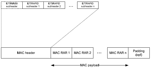
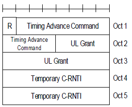
MAC Header and PDU structure for RACH Response (also called as RAR or Msg 2) has special format which has completely different from the MAC Header/PDU for user data. Overall structure for RAR MAC PDU structure is as shown below. If you are not familiar with detailed RACH procedure, it would be difficult to make any practical meaning out of this diagram. So, I would recommend you to read at least following two sections first.
< 36.321 v13.03 - Figure 6.1.5-4: Example of MAC PDU consisting of a MAC header and MAC RARs >
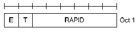
< 36.321 v13.03 - Figure 6.1.5-1: E/T/RAPID MAC subheader >
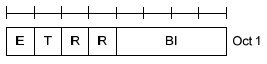
< 36.321 v13.03 - Figure 6.1.5-2: E/T/R/R/BI MAC subheader >
< 36.321 v13.03 - Figure 6.1.5-3: MAC RAR >

< 36.321 v13.03 - Figure 6.1.5-3a: MAC RAR for PRACH enhanced coverage level 2 or 3 >
< MAC PDU Structure /MAC Header for DL-SCH, UL-SCH and MCH >
In most case, one MAC PDU (MAC output) is made up of multiple chunks(MAC SDU = MAC Inputs) concatenated as follows;
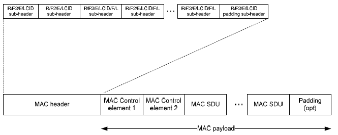
NOTE : As you see below, the illustrated structure is from 3GPP v13.03 (Rel 13). In case of Rel 8, 9, the F2 is assigned as 'R (Reserved)' field. Most of the MAC decoding example in this page is based on Rel 8,9, so you would not see F2 field in those example. In the example that apply Rel 11 and higher, I will explicitely comment about it.
< 36.321 v13.03 - Figure 6.1.2-1: R/R/E/LCID/F/L MAC subheader>

< 36.321 v13.03 - Figure 6.1.2-1a: R/F2/E/LCID/L MAC subheader >

< 36.321 v13.03 -Figure 6.1.2-2: R/F2/E/LCID MAC subheader >

NOTE : This subheader applies to the last subheader or Fixed sized MAC CE based on the following statement in 36.321-6.1.2 as stated below.
The last subheader in the MAC PDU and subheaders for fixed sized MAC control elements consist solely of the four header fields R/F2/E/LCID. A MAC PDU subheader corresponding to padding consists of the four header fields R/F2/E/LCID.
< 36.321 v13.03 -Table 6.2.1-1 Values of LCID for DL-SCH >
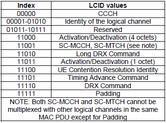
< 36.321 v13.03 - Table 6.2.1-2 Values of LCID for UL-SCH>

When you have BSR (Long BSR, Short BSR), you will have some additional information structured as shown in BSR page :
Let's understand the small keywords shown on the diagram. 36.321 6.2.1 MAC header for DL-SCH and UL-SCH has pretty good description.
- i) R : R means 'Reserved", meaning that it does not have any special meaning for now. It is always set to be '0' for now.
- ii) E : E means "Extension". This is an indicator to tell you if there is another fields following the subheader or not. '1' indicate there is at least one or more R/R/E/LCID fields following this field. '0' indicate there is no more R/R/E/LCID fields following this field implying 'the next byte is the start byte of MAC SDU or MAC CE or Padding'.
- iii) LCID : LCID stands for "Logical Channel ID", meaning Logical Channel Number.
- iv) F : F means 'Format'. This defines the length of 'L' field. If F is '0', the length of L field is 7 bit and if F is '1', the length of L field is 15 bit.
- v) F2 : This is new field defined from Release 13. If F2 is '0', the length of L field is determined by F field and if F is '1', the length of L field is 16 bit. It means that if F2 is '1', the structure of the header is as (C).
- vi) L : L means 'Length'. It shows the length of the MAC SDU. (Note that some MAC header, labeled as (D) does not have 'L' field. Then how can I know the length of MAC PDU, ie size of MAC PDU ? If there is no 'L' field, the size of MAC PDU is automatically set to be the same size of TBS(transport block size) in Byte unit.
Refer to MAC CE in Quick Reference
Refer to Backoff Indicator in Quick Reference
Now all these in mind, let's try with my second tip saying "try to anlayze real data by hand". I have the following MAC PDU from my equipment trace log ..
UL-SCH : 03 45 00 00 3C 33 63 00 00 80 01 00 00 00 00 ....
The first step is to analyze the first byte. For this, let me convert the first byte into binary format as follows :
03 = 00000011
Let's rearrange these bits according to MAC PDU diagram as follows : (Bit number start from MSB meaning "start from left")
* Bit 0 = R field = 0
* Bit 1 = R field = 0
* Bit 2 = E field = 0. This means that this header does not have any other fields following this field and it means 'the next byte is the start byte of MAC SDU or MAC CE or Padding'.
* Bit 3~7 = LCID field = 11 in Binary = 3 in decimal. This means the logical channel number for this PDU is '3'.
This is the end of analysis. All the remaining part is user data.
Now let's try with another data as follows :
UL-SCH : 20 06 1F 5F 09 72 43 FE 56 00 00 00 00 ......
In the same way as above, let's try with the first byte, 20.
20 = 00100000
* Bit 0 = R field = 0
* Bit 1 = R field = 0
* Bit 2 = E field = 1. This means that this header does have some 'Extension' and it means the this MAC PDU has the structure marked as 'A' or 'B' (Figure 6.1.2-1). Then which one is the right one. A ? or B ? The answer comes later. Now the important thing is that you have to decode the second Byte as well since 'E' field is '1'.
* Bit 3~7 = LCID field = 00000 in Binary. This means the logical channel number for this PDU is '00000' which is for UL CCCH (Refer to LCID Field for the meaning of this LCID field).
Since 'E' field is set to '1'. We have to decode the second Byte as well.
06 = 00000110
Bit number continues from from the first byte.
* Bit 8 (bit 0 of the Oct 2) = F field = 0. This means that the size of L field is 7 bit.
* Bit 9~15 (bit 1~bit 7 of the Oct 2)= L field = 0111100 = 06. This means the size of user data in this MAC PDU is 6 byte.
This is the end of second byte analysis. Is this all ? No.. when you have 'E' field to be '1'. You have to continue to decoding the header until you see the end.
Let's continue this analysis to the third byte, 1F as follows :
1F = 00011111
Process start from the begining because we know the first and second byte completes a complete header and I will restart the bit number as well.
* Bit 0 = R field = 0
* Bit 1 = R field = 0
* Bit 2 = E field = 0. It means that it does not have any 'extension'. It does not have any additional header. It means that this is the last header.
* Bit 3~7 = LCID = 11111. What does this mean ? If you see the table 6.2.1-1, 6.2.1-2.. this means 'MAC' padding. It means that this MAC PDU has MAC PDU after the user data. Then exactly which part is the padding and which part is the real user data. If you remember the first/second byte analysis, you should remember the size of real user data is 60 bytes. This, in turn, means that the data after the initial 60 bytes are the MAC padding.
Now let's try with another data as follows :
UL-SCH : 23 3C 1F 45 00 00 3C 33 63 00 00 80 01 00 00 00 00 ......
In the same way as above, let's try with the first byte, 23.
23 = 00100011
* Bit 0 = R field = 0
* Bit 1 = R field = 0
* Bit 2 = E field = 1. This means that this header does have some 'Extension' and it means the this MAC PDU has the structure marked as 'A' or 'B' (Figure 6.1.2-1). Then which one is the right one. A ? or B ? The answer comes later. Now the important thing is that you have to decode the second Byte as well since 'E' field is '1'.
* Bit 3~7 = LCID field = 11 in Binary = 3 in decimal. This means the logical channel number for this PDU is '3'.
Since 'E' field is set to '1'. We have to decode the second Byte as well.
3C = 00111100
Bit number continues from from the first byte.
* Bit 8 (bit 0 of the Oct 2) = F field = 0. This means that the size of L field is 7 bit.
* Bit 9~15 (bit 1~bit 7 of the Oct 2) = L field = 0111100 = 60. This means the size of user data in this MAC PDU is 60 byte.
This is the end of second byte analysis. Is this all ? No.. when you have 'E' field to be '1'. You have to continue to decoding the header until you see the end.
Let's continue this analysis to the third byte, 1F as follows :
1F = 00011111
Process start from the begining because we know the first and second byte completes a complete header and I will restart the bit number as well.
* Bit 0 = R field = 0
* Bit 1 = R field = 0
* Bit 2 = E field = 0. It means that it does not have any 'extension'. It does not have any additional header. It means that this is the last header.
* Bit 3~7 = LCID = 11111. What does this mean ? If you see the table 6.2.1-1, 6.2.1-2.. this means 'MAC' padding. It means that this MAC PDU has MAC PDU after the user data. Then exactly which part is the padding and which part is the real user data. If you remember the first/second byte analysis, you should remember the size of real user data is 60 bytes. This, in turn, means that the data after the initial 60 bytes are the MAC padding.
Now let's try with another data as follows : (This time you will see the MAC header is a little bit longer than previous ones. How do I know the MAC header is long ? Big hint is that I count the number of bytes from the start until I hit 1F which is 4 bytes in this case. MAC header does not always end with 1F, but in most case it would be the case)
UL-SCH : 3E 21 09 1F 00 00 00 A0 01 01 48 00 60 EB 82 80 00 00 00 00 00 00 00 00 00 00 00 00..
3E = 00111110
R = 0
R = 0
E = 1
LCID = 11110 = Long BSR
21 = 00100001 (LCID is not 1F, not special channel.. it is proper logical channel number.. so the following one or two bytes is part of the same subheader)
R = 0
R = 0
E = 1
LCID = 00001 = Logical Channel #1
09 = 00001001
F = 0
L = 00001001 = 9 Bytes (size of the first SDU. Be careful this is not PDU size)
1F = 00011111
R = 0
R = 0
E = 0
LCID = 11111 = Padding
Long BSR = 00 00 00
Now let's reorganize the above analysis according to the fig 6.1.2-3.
[Subheader #1]
3E = 00111110
R = 0
R = 0
E = 1
LCID = 11110 = Long BSR
[Subheader #2]
21 09 = 00100001 00001001
R = 0
R = 0
E = 1
LCID = 00001 = Logical Channel #1
F = 0
L = 00001001 = 9 Bytes (size of the first SDU. Be careful this is not PDU size)
[Subheader #3]
1F = 00011111
R = 0
R = 0
E = 0
LCID = 11111 = Padding
[MAC Control element #1]
Long BSR = 00 00 00
[MAC SDU #1]
= 9 bytes
= A0 01 01 48 00 60 EB 82 80
[Padding]
= 00 00 00 00 00 ...
Now let's analyze another MAC data. I will summerize the analysis in a little bit short format. If you have difficulties understanding this analysis, try reading < Example 3 > again.
UL-SCH : 3D 21 27 1F 00 A0 00 00 20 20 00 00 00 26 07 41 01 0B F6 00 00 00 00 00 00 00 00 00 00 02 E0 60 00 05 02 01 D0 11 D0 19 00 00 02 52 00 00 00 00 00 5C 08 02 00 00 00 00 ...
[The detail of MAC header]
3D : MAC subheader #1 ( Short BSR )
R = 0
R = 0
E = 1
LCID = 11101 = Short BSR
21 27 : MAC subheader #2 ( Logical Channel #1 )
R = 0
R = 0
E = 1
LCID = 00001 = Logical Channel #1
F = 0
L = 0100111 = 47 Bytes
1F : MAC subheader #3 ( Padding )
R = 0
R = 0
E = 0
LCID = 11111 = Padding
[MAC Control element #1]
Short BSR = 00
[MAC SDU #1]
= 47 bytes
= A0 00 00 20 20 00 00 00 26 07 41 01 0B F6 00 00 00 00 00 00 00 00 00 00 02 E0 60 00 05 02 01 D0 11 D0 19 00 00 02 52 00 00 00 00 00 5C 08 02
[Padding]
= 00 00 00 00 00 ...
This would be a special example which shows you that multiple MAC SDU are combined into a single MAC PDU. This example came from the signaling message "RRC Connection Reconfiguration + Attach Complete".
UL-SCH : 3D 21 09 22 11 1F 00 A0 04 04 10 00 40 EB C0 14 A0 00 00 48 00 E0 E8 60 00 6A 40 18 40 00 00 00 00 00 00 00 00 00 00 00 00...
3D : MAC subheader #1 ( Short BSR )
R = 0
R = 0
E = 1
LCID = 11101 = Short BSR
21 09 : MAC subheader #2 ( Logical Channel #1 )
R = 0
R = 0
E = 1
LCID = 00001 = Logical Channel #1
F = 0
L = 0001001 = 9 Bytes
22 11 : MAC subheader #3 ( Logical Channel #2 )
R = 0
R = 0
E = 1
LCID = 00010 = Logical Channel #2
F = 0
L = 0010001 = 17 Bytes
1F : MAC subheader #3 ( Padding )
R = 0
R = 0
E = 0
LCID = 11111 = Padding
[MAC Control element #1]
Short BSR = 00
[MAC SDU #1]
= 9 bytes
= A0 04 04 10 00 40 EB C0 14
[MAC SDU #1]
= 17 bytes
= A0 00 00 48 00 E0 E8 60 00 6A 40 18 40 00 00 00 00
[Padding]
= 00 00 00 00 00 ...
Let me give you another example. This is a MAC data for an IP packet going through DTCH.
DL-SCH : 03 18 04 50 9A C2 BC 25 C2 F0 BB 0B A0 B6 82 F0 9A 50 97 09 70 BC 26 94 2F 0A B0 BA 0B C2 F0 BC 2F 09 3A 09 27 09 A5 0B C2 69 42 DA 09 70 AE 82 4E 82 DA 0A B0 B7 0B 50 BC 2B A0 9A 4C 2D 42 75 0A B0 BC 2E C2 4D 42 F0 BC 2F 09 70 BC 26 94 2F 09 70 BC 25 C2 BC 2A 4C 2F 0A B0 BC 2F 0B 68 2F 0A B0 AB 09 A5 0B C2 DA 0B C2 F0 BC 2E C2 D4 2F 0B C2 AC 2A C2 47 00 44 14 F0 B6 82 F0 BC 25 C2 BA 0A B0 BC 2F 0B C2 5C 2D A0 BC 2F 0B A0 BC 2F 0B 68 2D A0 BC 26 94 24 E8 25 C2 F0 BC 2F 0A E8 25 C2 F0 BC 2D A0 B5 0B C2 F0 BC 2F 0B C2 5C 2D 42 F0 9D 30 BC 2E C2 D4 2F 0B C2 F0 BC 2E C2 D4 25 C2 69 42 F0 BC 2F 0B C2 F0 9A 50 BC 2F 0A B0 BC 2A C2 F0 BC 2F 0B C2 F0 AB 09 A5 0B 68 2F 0B C2
03 : MAC Header
R = 0
R = 0
E = 0
LCID = 3
This one has only one byte MAC header and it has only LCID and no other information. Then how do you know the size of the data ? This header does not have any size information. It means that all the data except the header part is a single SDU.
< Example 8 > Contention Resolution PDU
Following is one example of Contention Resolution message during the initial registration.
DL-SCH : 1C 50 00 00 00 00 07
1C : MAC Header
R = 0
R = 0
E = 0
LCID = 11100 = 1C = It means "This is MAC Header for Contention Resolution".
Since length of Contention Resolution is fixed to be 6 bytes (Refer to 36.321 6.1.3.4). This MAC header does not need to contain any additional F/L field. But there is one thing you have to care about. If the TBS size you allocated for PHY layer is exactly 56 bits, this is good enough. But if the TBS size is greater than 56, you have to add 'Padding' subheader, meaning the header should be like 3C 1F and the whole MAC PDU would be like 50 00 00 00 00 07 00 00 ..
[MAC SDU]
= 6 bytes
= 50 00 00 00 00 07
3D 22 17 1F 00 A0 00 00 48 01 A4 E0 00 00 00 00 20 E8 60 00 6A 40 18 40 00 00 00 00 00 00 00 00 00
3D : MAC subheader #1 ( Short BSR )
R = 0
R = 0
E = 1
LCID = 11101 = Short BSR
22 17 : MAC subheader #2
R = 0
R = 0
E = 1
LCID = 00010 = 2
F = 0
L = 010111 = 23 Bytes
1F : MAC subheader #3 ( Padding )
R = 0
R = 0
E = 0
LCID = 11111 = Padding
[MAC Control element #1]
Short BSR = 00
[MAC SDU #1]
= 23 bytes
= A0 00 00 48 01 A4 E0 00 00 00 00 20 E8 60 00 6A 40 18 40 00 00 00 00
This would be a special example which shows you that multiple MAC SDU are combined into a single MAC PDU. This example came from the signaling message "MAC Contention Resolution + RRC Connection Setup".
DL-SCH : 3C 20 12 1F 00 40 10 00 00 00 60 12 9B 3E 86 0F B5 79 E8 96 6C 30 64 99 60 2C 78 00 00 ...
3C : MAC subheader #1 ( Contention Resolution )
R = 0
R = 0
E = 1
LCID = 11100 = UE Contention Resolution Identity
20 12 : MAC subheader #2 ( CCCH )
R = 0
R = 0
E = 1
LCID = 00000 = CCCH
F = 0
L = 0010010 = 18 Bytes
1F : MAC subheader #3 ( Padding )
R = 0
R = 0
E = 0
LCID = 11111 = Padding
[MAC Control element #1]
UE Contention Resolution Identity = 00 40 10 00 00 00 (6 Bytes fixed)
[MAC SDU #1]
= 18 bytes
= 60 12 9B 3E 86 0F B5 79 E8 96 6C 30 64 99 60 2C 78 00
[Padding]
= 00 ...
This is an example of MAC CE shown at step (7) of Closer view on Carrier Aggregation Establishment - 2CC.
DL-SCH : 3B 1F 02 00 00 ...
3B : MAC subheader #1 ( MAC-CE : Activation / Deactivation )
R=0
F2=0
E=1
LCID = 11011 (MAC CE-Activation/Deactivation)
1F = 00011111 : Subheader #2]
R = 0
R = 0
E = 0
LCID = 11111 = Padding
02 : Payload - MAC CE( MAC-CE : Activation / Deactivation )
C7 = 0
C6 = 0
C5 = 0
C4 = 0
C3 = 0
C2 = 0
C1 = 1
R = 0
NOTE : Refer to MAC CE(Activation/Deactivation) page for the details
Now let's go through some example of bad cases. In some way, the examples of bad cases would give you more help for troubleshooting.
< Example 1 : Bad Case >
UL-SCH : 3E 1F 00 00 00 A0 01 01 48 00 60 EB 82 80 07 41 01 0B 00 00 00 00..
[Subheader #1]
3E = 00111110
R = 0
R = 0
E = 1
LCID = 11110 = Long BSR
[Subheader #2]
1F = 00011111
R = 0
R = 0
E = 0
LCID = 11111 = Padding
[MAC Control element #1]
Long BSR = 00 00 00
You see that there no subheader for normal MAC data (MAC SDU). In this case, all the payload (A0 01 01 48 00 60 EB 82 80 07 41 01 0B) coming after Long BSR is regarded as a MAC padding. So they are discarded and does not go up to higher layer.
< Example 2 : Bad Case >
This case may or may not cause any problem depending on higher layer implementation on network side. But I take this as a bad case
UL-SCH : 3D 21 33 1F 00 A0 00 00 20 20 00 00 00 26 07 41 01 0B F6 00 00 00 00 00 00 00 00 00 00 02 E0 60 00 05 02 01 D0 11 D0 19 00 00 02 52 00 00 00 00 00 5C 08 02 00 00 00 00 00 00 ..
Following is the analysis of the header part
3D : MAC subheader #1 ( Short BSR )
R = 0
R = 0
E = 1
LCID = 11110 = Long BSR
21 33 : MAC subheader #2 ( Logical Channel #1 )
R = 0
R = 0
E = 1
LCID = 00001 = Logical Channel #1
F = 0
L = 0110011 = 51 Bytes (This seems to be MAC PDU size, not SDU size.. this value MAY cause some problem)
1F : MAC subheader #3 ( Padding )
R = 0
R = 0
E = 0
LCID = 11111 = Padding
00 : MAC Control Element #1(Short BSR)
MAC SDU #1 (51 Bytes)
= A0 00 00 20 20 00 00 00 26 07 41 01 0B F6 00 00 00 00 00 00 00 00 00 00 02 E0 60 00 05 02 01 D0 11 D0 19 00 00 02 52 00 00 00 00 00 5C 08 02 00 00 00 00 00
In this case, there would be no problem for the MAC Data (PDU) to go through to the higher layer, but it carries 5 additional trailing 0s. If the higher layer (RRC/NAS) on Network side can properly ignore (chop off) these trailing bytes there would be no problem, but the higher layer complain about this, this incorrect SDU size would cause problem.
Refer to DRX page.