Every UMTS link runs on the same carrier as every other link in the cell, so the power of one UE is interference for all the others. Power control keeps each link at the power it needs and no more. This page starts with how the channel powers move in a real log, then lists the specification tables behind the gain factors, and then walks through the R99 loops and the HSPA extensions.
Topics I will discuss in this post is a follows.
- Overview
- Specification and Parameters
- List of Channel Power that does not change
- R99 Downlink Power Control
- R99 Uplink Power Control
- Downlink Power Control in HSPA
- Uplink Power Control in HSPA
- Reference
Overview
In WCDMA, all UEs in a cell share one carrier and are separated only by their codes. A UE that transmits too loud raises the interference for every other UE, and a UE that transmits too quietly loses its own link. So the network tries to keep every link at the power it needs, and it corrects that power many times per second. The two logs below show what this looks like on a real connection.
If you are totally new to this topic, I recommend you to read "Overview" section of LTE Power Control page first.
One thing I want to add in this section is that power of most of the channels changes very dynamically throughout the call setup and data communication.
Following is one example showing the power of each of Uplink physical channels for HSUPA. Again this is only one example and detailed power profile would vary depending on data rate and parameter settings related to power control.
Focusing on the stage where packet communication occurs, you will see various physical channels and the channel power changes dynamically. This is the power changes for the communication using the network simulator with direct RF connector (by RF cable), so the range of power change is not so huge but if you collect the same data in live network you would see more dynamic changes and if it is while you are moving around a cell, you would see even more dynamic changes.
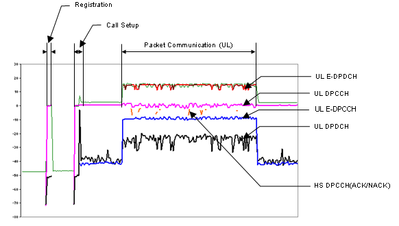
Uplink channel power over one HSUPA session. The E-DCH channels appear only in the packet communication phase, and the other channels move together with the DPCCH.
Registration and Call Setup are short bursts : Before the packet phase, the UE sends only short transmissions, so the traces rise and fall quickly at the left of the plot.E-DPDCH is the strongest channel during packet communication : It carries the user data, so it sits at the top of the plot in the packet phase and drops out when the phase ends.Several traces show the same ripples : The channels do not move independently. This is a first hint for question ii below: the channels are not controlled one by one.
The result shown above is shows the power changes of each channels along the timeline. There is another common way of showing the power changes is to show the power in code domain as shown below.
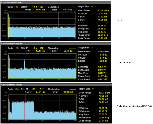
Downlink code domain power in three states. The P-CPICH keeps the same absolute power, while its share of the total power falls as HSDPA codes are added.
IDLE : Only the common channels are on the air. The mean power is -62.16 dBm, and the P-CPICH is -4.47 dB relative to it.Registration : One more code appears beside the common channels, for the dedicated channel of the registration signalling. The mean power hardly changes, -61.94 dBm.Data Communication - HSDPA : A wide block of codes carries the HS-PDSCH. The mean power rises to -52.77 dBm, and the P-CPICH falls to -13.72 dB.The P-CPICH itself did not change : -62.16 - 4.47 = -66.63 dBm, and -52.77 - 13.72 = -66.49 dBm. Only the total around it grew by about 9.4 dB.
Before you jump into the detailed power control process, I would give you a list of questions to which you have to find answer (on your own -:)
i) Why each of the channel power should changes like this ?
ii) There are many channels, each of the channel power is controlled separately ? or there is a master (reference channel) being directly controled and all the other channels changes according to the master channel ?
iii) How often this kind of power control (power changes) happens ? (every 1 seconds? every 1 ms seconds ? every frame ? every slot ?)
The rest of the page answers these three questions. The short answers are: the loops follow the radio conditions and the data rate, one channel per direction is the reference and the others follow it with fixed ratios, and the inner loop runs once per slot.
Power control is about interference : Every watt a UE saves is less interference for the other UEs on the same carrier.Relative numbers can hide absolute ones : A code domain display shows each code relative to the total, so a constant channel can look as if it changed.A test setup shows less movement than a live network : A cabled connection has no fading, so the loops have little to correct.
Specification and Parameters
If you pick up any books about mobile communication, there would be at least one section or chapter dealing with the power control process and in many cases you will see a lot of parameters (e.g, Beta c, Beta d, Beta hs etc) without being explained. In fact, it is not easy to explain those parameters in simple/clear way. So I would just give you some reference points of those parameters which is critical to power control process.
Whenever you come across any power control parameters from textbook or internet, you can use this section as a quick reference for those parameters.
- 25.213 - 4.2.1.1 DPCCH/DPDCH
- 25.213 - 4.2.1.2 HS-DPCCH
- 25.213 - 4.2.1.3 E-DPDCH/E-DPCCH
- 25.213 - 4.2.2.2 PRACH message part
All of these clauses use the same idea. Each uplink channel is multiplied by a gain factor after spreading: βc for the DPCCH, βd for the DPDCHs, βhs for the HS-DPCCH, βec for the E-DPCCH and βed for the E-DPDCHs. The gain factors fix the amplitude ratio between the channels, and the inner loop moves all of them together.
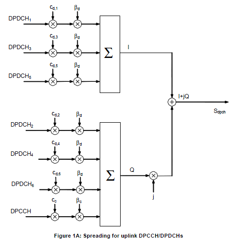
25.213 Figure 1A below shows the DPCCH and the DPDCHs. DPDCH1, DPDCH3 and DPDCH5 go to the I branch, and DPDCH2, DPDCH4, DPDCH6 and the DPCCH go to the Q branch. Every DPDCH is weighted by the same βd, and the DPCCH by βc.
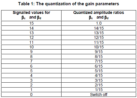
25.213 Table 1 below maps the signalled values 0 to 15 to amplitude ratios in steps of 1/15. The value 15 means 1.0, and the value 0 switches the channel off. At every instant, at least one of βc and βd has the amplitude 1.0.
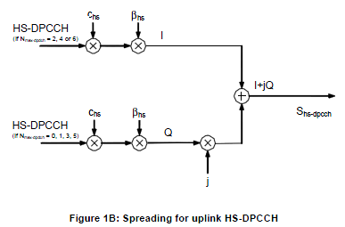
25.213 Figure 1B below adds the HS-DPCCH with its own gain factor βhs. It goes to the I branch when Nmax-dpdch is 2, 4 or 6, and to the Q branch otherwise.
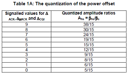
βhs is not signalled directly. Higher layers signal ΔACK, ΔNACK and ΔCQI, and 25.213 Table 1A below turns each of them into Ahs = βhs/βc. The picture stops at the value 9. In 25.213 v19.0.0 the table continues up to 12, which gives 76/15. 25.331 also adds -r11 versions of these IEs, such as DeltaACK-r11 and DeltaCQI-r11, with the range 0 to 10.
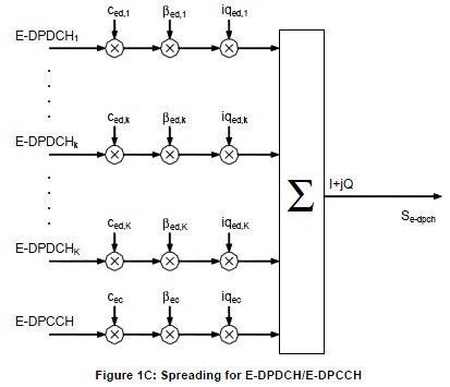
25.213 Figure 1C below shows the E-DCH channels. Each E-DPDCHk has its own gain factor βed,k and its own I/Q mapping iqed,k, and the E-DPCCH has βec and iqec. All of them are summed into one I+jQ stream, Se-dpch.
25.213 Table 1B below turns the signalled ΔE-DPCCH into Aec = βec/βc. The picture shows the values 0 to 8. In 25.213 v19.0.0 the table runs to 15, which gives 151/15, and 25.331 signals 9 to 15 with the Extended-E-DPCCH-DPCCH-PowerOffset IE.
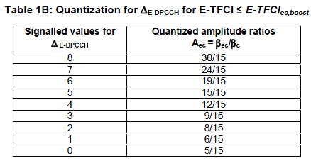
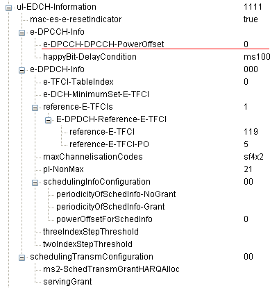
The decoded RRC tree below shows where these values come from. e-DPCCH-DPCCH-PowerOffset is ΔE-DPCCH, here 0, so Aec = 5/15. Under reference-E-TFCIs, the message gives one reference E-TFCI, 119, with reference-E-TFCI-PO 5. That PO is ΔE-DPDCH for the reference E-TFCI, and Table 1B.1 turns it into Aed = 11/15.
25.213 Table 1B.1 below turns ΔE-DPDCH into Aed = βed/βc for the reference E-TFCIs. The values 0 to 29 run from 5/15 to 168/15. The third column shows which E-DPDCH modulation may be used in the same subframe, and 4PAM is allowed only for the values 10 to 19.
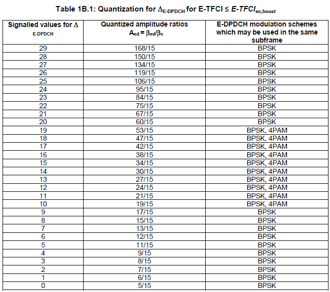
The tables that the picture does not show are listed below. They cover the E-TFCIs above E-TFCIec,boost, where the E-DPCCH is boosted for a better phase reference, and the HARQ offset.
- Table 1B.2: Quantization for βed,k/βc for E-TFCI ≤ E-TFCIec,boost
- Table 1B.2A: Quantization for ΔE-DPDCH for E-TFCI > E-TFCIec,boost
- Table 1B.2B: Quantization for βed,k/β c for E-TFCI > E-TFCIec,boost
- Table 1B.3: HARQ offset Δharq
Every gain factor is relative to βc : Ahs, Aec and Aed are all ratios to the DPCCH gain factor.RRC signals indexes, not amplitudes : A log shows the index, and the 25.213 table turns it into the amplitude ratio.βed is computed for each E-TFC : RRC gives it only for the reference E-TFCIs, and 25.214 clause 5.1.2.5B.2 derives the other E-TFCs from them.
List of Channel Power that does not change
There are a set of channels, the power of which is normally fixed during the cell planning and does not change dynamically. It means that these channels are not the target of power control, but I thought I'd better make list of these because they are still a part of total channel power.
|
Channel |
Main Function |
PCPICH (Primary Common Pilot Channel) |
Carries Common Pilot that all UE uses as a reference power of a cell |
P-SCH(Primary Sync Channel) |
Carries the primary synchronization code |
S-SCH(Secondary Sync Channel) |
Carries the secondary synchronization code |
AICH (Aquisition Indicator Channel) |
Carries the Aquisision Indicator which is a response for PRACH Preamble |
PICH (Paging Indicator Channel) |
Carries Paging Indicator |
P-CCPCH (Primary Common Control Physical Channel) |
Carries BCH (Broadcast Channel) data |
|
S-CCPCH(Secondary Common Control Physical Channel) |
Carries FACH or PCH data |
The UE needs the power of one of these channels in absolute terms. It reads the IE "Primary CPICH Tx power" from system information. It then uses that value for the open loop estimate of the first PRACH preamble: Preamble_Initial_Power = Primary CPICH TX power - CPICH_RSCP + UL interference + Constant Value. So the P-CPICH power is not only a fixed share of the cell power. It is also the reference for the uplink open loop.
Some of these powers are not fully fixed. The S-CCPCH carries FACH and PCH, and 25.214 allows its TFCI and pilot fields to be offset from the data field, and these offsets may vary in time. In 25.214, the transmit power of the downlink channels is determined by the network, and the ratio between downlink channels is not specified in general. For AICH and PICH, the UE is told their power relative to the P-CPICH by higher layers.
These channels are outside the loops : No TPC command moves them. They are set by network planning.P-CPICH is the anchor : The UE measures CPICH RSCP and knows the P-CPICH transmit power, so it can estimate the path loss.They still take a share of the cell power : The code domain display in the Overview section shows them as a fixed floor under the dedicated traffic.
R99 Downlink Power Control
Downlink power control keeps each dedicated downlink at the SIR the UE needs. The UE is the only place where the downlink quality can be measured, so the UE makes the decision and the network follows it.
"Downlink Power Control" means "change of downlink power based on TPC command carried by uplink control channel(UL DPCCH)".
Overall Procedure is as follows :
i) UE measures DL DPCCH SIR at each slot which is 10/15 ms, 0.667ms.
ii) It compares the measured SIR with the specified SIR target.
iii) If the measured SIR is greater than the target SIR, UE put the TPC command 0 into TPC field of UL DPCCH which tells Network to decrease the downlink power.
iv) If the measured SIR is poorer than the target SIR, UE put the TPC command 1 into TPC field of UL DPCCH which tells Network to increase the downlink power.
The SIR target in steps ii to iv is not fixed. It comes from an outer loop in the UE. The network sends a BLER quality target for each transport channel in the IE "DCH quality target", and the UE adjusts its downlink SIR target to meet that quality. So the inner loop tracks fading every slot, and the outer loop moves the target more slowly.
Two network settings change how the loop runs. With DPC_MODE 0, the UE sends a new TPC command in every slot. With DPC_MODE 1, the UE repeats the same TPC command over 3 slots, and the network updates its power every three slots. The network step size can be 0.5, 1, 1.5 or 2 dB, and 1 dB is mandatory for the UTRAN to support.
The loop moves the DPCCH and the DPDCHs by the same amount, so their power ratio does not change. Inside the DPCCH, the TFCI, TPC and pilot fields are offset from the DPDCH power by PO1, PO2 and PO3.
TPC 0 means down and TPC 1 means up : The same coding is used in both directions.Two loops work together : The inner loop follows the SIR target every slot, and the outer loop sets that target from the BLER target.DPC_MODE 1 slows the loop to 500 Hz : One command per 3 slots is 500 commands per second, instead of 1500.
R99 Uplink Power Control
"Uplink Power Control" means "change of uplink power based on TPC command carried by downlink control channel(DL DPCCH)". As you see in the figures below, both downlink DPCCH and uplink DPCCH slot has a special field called 'TPC (Transmission Power Control)' field.
Since every slot has this field, you may easily infer that the power control in R99 would happen once in every slot (10/15 ms).
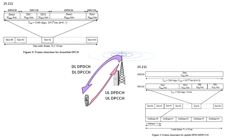
R99 dedicated channel slots. Both the downlink DPCCH part and the uplink DPCCH carry a TPC field in every slot.
Overall Uplink Power control Procedure is as follows.
i) Network detect and evaluate uplink transmission power at each slot.
ii) Compare the measured power with the specified SIR target.
iii) If the measured power is less than SIR target, Network put a "Power Up" command in TPC field on downlink DPCCH and the measured power is much higher than SIR target, Network may put a "Power Down" command in the TPC field.
iv) UE decode the downlink DPCCH and figure out TPC field.
v) UE increase it's transmission power if the TPC field has "Power Up" command and vice versa.
In 25.214, the quantity in steps i to iii is the SIR of the received uplink DPCH, not the power itself. Each cell in the active set estimates SIRest and compares it with SIRtarget. If SIRest > SIRtarget, the cell sends TPC command 0, and if SIRest < SIRtarget, it sends TPC command 1. So the network sends a command in every slot. It does not wait until the SIR is much higher than the target.
The UE turns the received commands into one TPC_cmd per slot with the algorithm that the network configures. Algorithm 1 changes the power in every slot by the step size ΔTPC, which is 1 dB or 2 dB. Algorithm 2 always uses 1 dB and can emulate a smaller step, or turn the loop off with an alternating series of commands. In soft handover, several cells send TPC commands, and the UE combines them.
Quick question : Why Network have to send "Power Down" command when the measured power is too much better than the target SIR ?
The answer is interference. Every UE on the carrier sees the power of the other UEs as noise, so a UE that transmits more than it needs lowers the capacity of the whole cell. It also uses more battery. The network therefore asks for a power decrease as soon as the SIR is above the target.
The loop runs at 1500 Hz : One TPC command per slot and 15 slots per 10 ms give 1500 commands per second.The Node B measures SIR, not power : The same received power can be good or bad depending on the interference, so the loop compares SIR.Soft handover needs combining : With several cells in the active set, the UE decides one TPC_cmd from all the received commands.
Downlink Power Control in HSPA
HSDPA changes the downlink logic. The HS-PDSCH is shared and scheduled every 2 ms, so a fast per-UE power loop does not fit it. Instead, the Node B changes the data rate to match the channel, and the power stays under its own control.
25.214 leaves both new channels to the Node B. The HS-PDSCH power control is under the control of the Node B, and all HS-PDSCHs for one UE are sent with equal power. With 16QAM or 64QAM, the UE may assume that the power stays constant within the HS-DSCH subframe. The HS-SCCH power control is also under the control of the Node B, and it may follow the TPC commands from the UE or any other procedure.
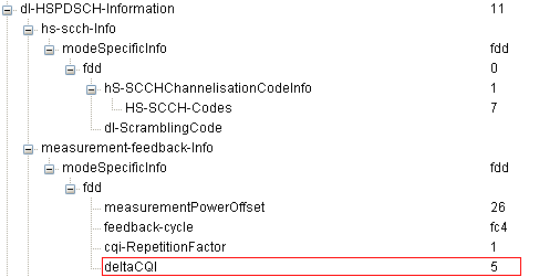
The link adaptation uses the CQI. To make the CQI meaningful, the UE assumes a total received HS-PDSCH power of PCPICH + Γ + Δ. Here Γ is the measurement power offset from higher layers, and Δ is a reference power adjustment from the CQI table. The decoded dl-HSPDSCH-Information in the Uplink Power Control in HSPA section below shows measurementPowerOffset 26. 25.331 defines the actual value as the IE value x 0.5, so Γ is 13 dB here.
The dedicated part of the downlink still has an inner loop. The DPCH, or the F-DPCH when there is no downlink DPCH, keeps its TPC field and follows the TPC commands from the UE. With F-DPCH, the uplink TPC commands of an HSPA UE come from the F-DPCH.
HSDPA uses rate control, not power control : The Node B keeps the HS-PDSCH power and changes the transport format from the CQI.Measurement power offset ties CQI to power : The UE computes the CQI as if the HS-PDSCH were PCPICH + Γ + Δ.F-DPCH keeps the uplink loop alive : Even with all data on HS-DSCH, the UE still needs downlink TPC commands for its uplink DPCCH.
Uplink Power Control in HSPA
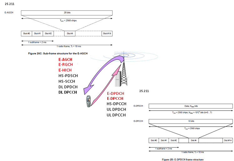
Uplink Power Control in HSUPA is very complicated because there are so many different physical channels coming into play. As you see in the following illustration, five different physical channels are working simultaneously in Uplink side and we have to think of the power control of each of these channel. When we are talking about UE's total output power in HSUPA, it means all of these physical channel power summed together (= DPCCH + DPDCH + HS-DPCCH + E-DPCCH + E-DPDCH)
The diagram below lists the channels in each direction. In the downlink, E-AGCH, E-RGCH and E-HICH are added for HSUPA, with the 25.211 sub-frame structure of the E-AGCH at the top left. In the uplink, E-DPDCH and E-DPCCH are added, with the 25.211 E-DPDCH frame structure at the bottom right.
Overall UL power control logic is as follows (You may think that UL Power control of HSUPA is one of the most complicated process of any kind of power controls since too many factors are get involved):
i) DL (DPDCH+DPCCH) slot carries TPC bits (Power Control bits) to UE.
ii) UE decode the TPC bits and changes it's UL DPCCH power accordingly.
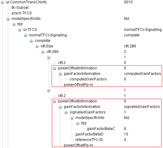
iii) UL DPDCH Power is adjusted accordingly based on UL DPCCH Power. (The mapping between this RRC value and real gain factor in physical layer are defined in 25.213 Table 1).
The decoded ul-CommonTransChInfo below shows the two ways RRC gives βc and βd for each TFC. For CTFC 0, computedGainFactors tells the UE to compute them from a reference TFC. For CTFC 1, signalledGainFactors gives gainFactorBetaC 8 and gainFactorBetaD 15, so βc = 8/15 and βd = 1.0 by 25.213 Table 1.
iv) UL E-DPCCH Power is adjusted based on UL DPCCH Power.
v) UL E-DPDCH Power is adjused based on UL DPCCH Power. (The offset between E-DPDCH and DPCCH is defined by RRC message as follows).
In the decoded ul-EDCH-Information below, the underlined e-DPCCH-DPCCH-PowerOffset is the offset of step iv. The offset of step v is reference-E-TFCI-PO in the same message, and 25.214 clause 5.1.2.5B.2 computes βed from βc and that value.
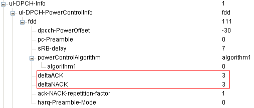
vi) Now the remaining channel is HS-DPCCH. This channel power is also determined based on UL DPCCH according to following RRC Information elements.
The two decoded trees below carry those IEs. The IE ul-DPCH-PowerControlInfo gives deltaACK 3 and deltaNACK 3, and dl-HSPDSCH-Information gives deltaCQI 5. By 25.213 Table 1A, this is Ahs = 9/15 for ACK and NACK, and 15/15 for CQI.
The sketch below puts the six steps together. The DPCCH, drawn in red, is the only channel that the TPC commands move directly. Every other trace keeps a fixed distance from it and moves with it.
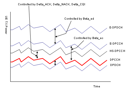
HSUPA uplink power. The DPCCH follows the TPC commands, and each other channel follows the DPCCH through its own gain factor.
DPDCH : Offset from the DPCCH by βd/βc.HS-DPCCH : Offset from the DPCCH by ΔACK, ΔNACK and ΔCQI, so its power changes with what it carries in each slot.E-DPCCH : Offset from the DPCCH by βec, from ΔE-DPCCH.E-DPDCH : The sketch draws the Beta_ed arrow between E-DPCCH and E-DPDCH. In 25.213 and 25.214, βed is a ratio to βc, so the E-DPDCH also follows the DPCCH, not the E-DPCCH.
The formula block below is written for a network simulator, where the tester sets a UE target power instead of running a real loop. The idea is the same. The target applies to the DPCCH and DPDCH, and the other channels add their own power on top of it.
When on an HSPA connection, you must set UE Target Power as follows:
UE Target Power = ( Desired Total UE Power ) - ( Power Change Due to HS-DPCCH, E-DPCCH and E-DPDCH )
Where
Desired Total UE Power is the total output power level you desire from the UE, including DPCCH, DPDCH, HS-DPCCH, E-DPCCH and E-DPDCH.

Let's read the equation. The power of each channel is proportional to the square of its gain factor, so the total power of all five channels is proportional to βc2 + βd2 + βhs2 + βec2 + βed2. The equation divides that sum by the DPCCH and DPDCH part, βc2 + βd2, and converts the ratio to dB. With no HS-DPCCH, E-DPCCH or E-DPDCH, the ratio is 1 and the change is 0 dB.
The DPCCH is the master channel : TPC commands move it, and every other uplink channel follows it through a gain factor.Gain factors change the mix, not the loop : 25.214 says that the setting of the E-DPDCH gain factors is independent of the inner loop power control.Total power is a sum of squares : Adding a channel with gain factor β adds β2 to the total, relative to the DPCCH.
Reference
- 3GPP TS 25.211 v19.0.0 : Physical channels and mapping of transport channels onto physical channels (FDD)
- 3GPP TS 25.213 v19.0.0 : Spreading and modulation (FDD)
- 3GPP TS 25.214 v19.0.0 : Physical layer procedures (FDD)
- 3GPP TS 25.331 v19.0.1 : Radio Resource Control (RRC); Protocol specification