This page shows the 1.28 Mcps TDD version of a common reference radio bearer. It carries an interactive or background PS RAB of UL 64 kbps and DL 144 kbps, plus signalling radio bearers of 3.4 kbps in each direction. 34.108 clause 6.11.5.4.1.29 defines it for radio bearer testing in TD-SCDMA. The numbers on this page come from three places: the transport channel tables, the physical channel tables and a Radio Bearer Setup capture. We will see that they describe the same configuration.
Let's start from the physical channel tables, then place the codes in the time slots, then find the same values in the capture. The last section works back from the physical bits to the 144 kbps data rate.
- What are the physical channel parameters?
- How are the codes and time slots allocated?
- How does the Radio Bearer Setup carry this configuration?
- Where does the data rate come from?
- Reference
What are the physical channel parameters?
34.108 describes each reference bearer with two kinds of tables. The transport channel tables say what RLC and MAC deliver. The physical channel tables say how many codes and time slots carry it on the DPCH. The two tables below are the physical channel tables for the uplink and the downlink. The red notes on each image explain how to read the rows.
The uplink table below has two columns. Physical 1 is the configuration that the capture on this page uses, one SF2 code in 2 time slots per radio frame. Physical 2 is an alternative with one SF1 code. The same uplink table serves every UL 64 kbps bearer in this series.
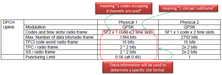
SF2 x 1 code x 2 time slots : one SF2 code takes the code space of 8 SF16 codes. Two time slots per 10 ms radio frame means one time slot in each 5 ms subframe.1384 data bits per radio frame : 25.221 Table 8G gives 692 data bits per slot for uplink slot format 48. This format is SF2 with 16 TFCI bits and 2 bits each of SS and TPC. Two slots give 2 x 692 = 1384.TFCI, TPC and SS : the TFCI code word is 16 bits, and TPC and SS each take 2 bits in each of the 2 time slots.Puncturing limit 0.56, alt 0.48 : 25.222 allows rate matching to puncture up to (1 - PL) x 100 percent of the bits, so 0.56 allows up to 44 percent.Physical 2 needs no puncturing : one SF1 code in 2 time slots gives 2792 bits, which is 2 x 1396 bits of uplink slot format 63. Its puncturing limit is 1.
The downlink table below uses SF16 codes in more time slots than the uplink. The number of codes and the number of time slots together set the capacity.
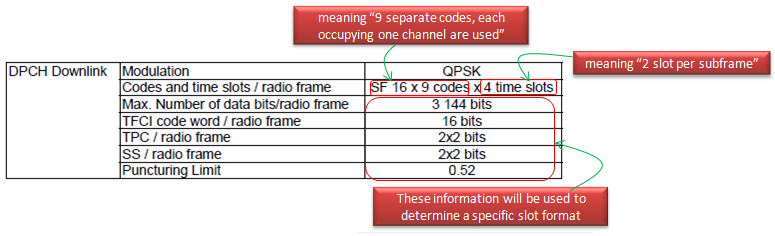
SF16 x 9 codes x 4 time slots : 9 SF16 codes in each of 2 time slots per subframe.3144 data bits per radio frame : the first time slot carries 780 bits. In 25.221 Table 8F, one code uses slot format 8 with 76 data bits, and 8 codes use slot format 0 with 88 each. The second time slot has 9 codes with slot format 0, so 792 bits. One subframe carries 1572 bits, and the radio frame carries 3144.Puncturing limit 0.52 : rate matching may puncture up to 48 percent of the bits.The downlink has more than twice the uplink capacity : 3144 against 1384 bits per frame, for 144 against 64 kbps.
How are the codes and time slots allocated?
The tables give counts of codes and time slots, but they do not say which ones. The slot map below places them in two 5 ms subframes. It uses the same time slots that the capture on this page assigns, so the map and the capture can be checked against each other.
Each column of the map is a time slot, and each row is one of the 16 code channels of SF16. The grey columns between Slot 0 and Slot 1 are DwPTS, the guard period and UpPTS. Green cells are uplink, orange cells are downlink, and each label is a slot format from 25.221.
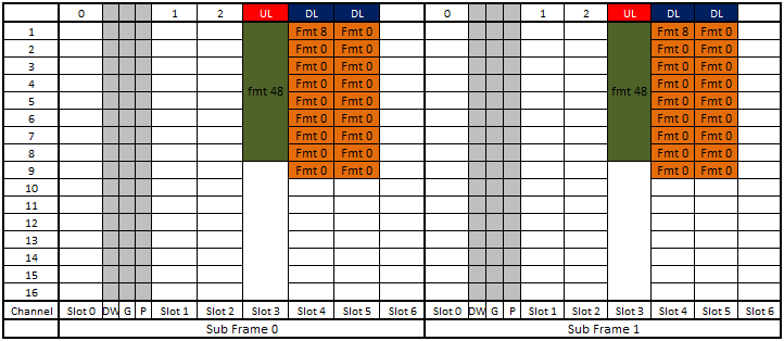
Slot 3 carries the uplink : one SF2 code with slot format 48 fills the rows of codes 1 to 8.Slots 4 and 5 carry the downlink : each uses codes 1 to 9. Only code 1 of slot 4 uses slot format 8, so TFCI, TPC and SS appear once per subframe.Subframe 1 repeats subframe 0 : this gives the 2 time slots per radio frame that the tables count for each slot position.Slot 0 stays free of the DPCH : 25.221 clause 5A.3.1 maps the P-CCPCH, which carries the BCH, onto the first two codes of time slot 0.
How does the Radio Bearer Setup carry this configuration?
The capture below is the physical channel part of a RADIO BEARER SETUP for this bearer. It starts in the middle of the message at ul-DPCH-Info, so the upper levels of the tree are not shown. The page gives it in two parts, uplink and then downlink. The fields in red are the ones that map to the tables and the slot map above.
Decoded RRC message from a tester log,
            | | +-ul-DPCH-Info ::= SEQUENCE [1]
            | |   +-ul-DPCH-PowerControlInfo ::= CHOICE [tdd] OPTIONAL:Exist
            | |   | +-tdd ::= SEQUENCE [1]
            | |   |   +-ul-TargetSIR ::= INTEGER (0..62) [48] OPTIONAL:Exist
            | |   |   +-ul-OL-PC-Signalling ::= CHOICE [individuallySignalled]
            | |   |     +-individuallySignalled ::= SEQUENCE
            | |   |       +-tddOption ::= CHOICE [tdd128]
            | |   |       | +-tdd128 ::= SEQUENCE
            | |   |       |   +-tpc-StepSize ::= INTEGER (1..3) [1]
            | |   |       +-primaryCCPCH-TX-Power ::= INTEGER (6..43) [12]
            | |   +-modeSpecificInfo ::= CHOICE [tdd]
            | |     +-tdd ::= SEQUENCE [110]
            | |       +-ul-TimingAdvance ::= CHOICE [enabled] OPTIONAL:Exist
            | |       | +-enabled ::= SEQUENCE
            | |       |   +-tddOption ::= CHOICE [tdd128]
            | |       |     +-tdd128 ::= SEQUENCE [10]
            | |       |       +-ul-SynchronisationParameters ::= SEQUENCE OPTIONAL:Exist
            | |       |       | +-stepSize ::= INTEGER (1..8) [1]
            | |       |       | +-frequency ::= INTEGER (1..8) [1]
            | |       |       +-synchronisationParameters ::= SEQUENCE OPTIONAL:Omit
            | |       +-ul-CCTrCHList ::= SEQUENCE OF SIZE(1..maxCCTrCH[8]) [1] OPTIONAL:Exist
            | |       | +-UL-CCTrCH-r4 ::= SEQUENCE [11]
            | |       |   +-tfcs-ID ::= INTEGER (1..8) [1] OPTIONAL:Exist
            | |       |   +-ul-TargetSIR ::= INTEGER (0..62) [48]
            | |       |   +-timeInfo ::= SEQUENCE [10]
            | |       |   | +-activationTime ::= INTEGER (0..255) [0] OPTIONAL:Exist
            | |       |   | +-durationTimeInfo ::= INTEGER OPTIONAL:Omit
            | |       |   +-commonTimeslotInfo ::= SEQUENCE [11] OPTIONAL:Exist
            | |       |   | +-secondInterleavingMode ::= ENUMERATED [frameRelated]
            | |       |   | +-tfci-Coding ::= ENUMERATED [tfci-bits-16] OPTIONAL:Exist
            | |       |   | +-puncturingLimit ::= ENUMERATED [pl0-56]
            | |       |   | +-repetitionPeriodAndLength ::= CHOICE [repetitionPeriod1] OPTIONAL:Exist
            | |       |   |   +-repetitionPeriod1 ::= NULL
            | |       |   +-tddOption ::= CHOICE [tdd128]
            | |       |     +-tdd128 ::= SEQUENCE [1]
            | |       |       +-ul-CCTrCH-TimeslotsCodes ::= SEQUENCE OPTIONAL:Exist
            | |       |         +-dynamicSFusage ::= BOOLEAN [FALSE]
            | |       |         +-firstIndividualTimeslotInfo ::= SEQUENCE [0]
            | |       |         | +-timeslotNumber ::= INTEGER (0..6) [3]
            | |       |         | +-tfci-Existence ::= BOOLEAN [TRUE]
            | |       |         | +-midambleShiftAndBurstType ::= SEQUENCE
            | |       |         | | +-midambleAllocationMode ::= CHOICE [defaultMidamble]
            | |       |         | | | +-defaultMidamble ::= NULL
            | |       |         | | +-midambleConfiguration ::= INTEGER (1..8) [8]
            | |       |         | +-modulation ::= ENUMERATED [mod-QPSK]
            | |       |         | +-ss-TPC-Symbols ::= ENUMERATED [one]
            | |       |         | +-additionalSS-TPC-Symbols ::= INTEGER OPTIONAL:Omit
            | |       |         +-ul-TS-ChannelisationCodeList ::= SEQUENCE OF SIZE(1..2) [1]
            | |       |         | +-UL-TS-ChannelisationCode ::= ENUMERATED [cc2-1]
            | |       |         +-moreTimeslots ::= CHOICE [noMore]
            | |       |           +-noMore ::= NULL
Start with the uplink. The ul-TargetSIR is 48, and 25.331 gives the actual value as IE x 0.5 - 11, so the target is 13 dB. The primaryCCPCH-TX-Power of 12 dBm is the P-CCPCH power that the UE uses for its path loss estimate, and the TPC step size is 1 dB. The single UL-CCTrCH uses tfci-bits-16 and pl0-56, which are the 16 TFCI bits and the 0.56 puncturing limit of the uplink table. Its only time slot is timeslotNumber 3, with a TFCI, QPSK and one SS and TPC symbol. The code is cc2-1, the first SF2 code.
A few more fields complete the uplink. The midambleConfiguration is 8, and 25.331 defines the actual value as IE x 2, so the midamble configuration is 16. The uplink synchronisation parameters stepSize 1 and frequency 1 are the default values in 25.331. 25.224 clause 5.2.4 uses them as k and M. The UE moves its uplink timing by k/8 chip per SS command, and it combines the SS commands of up to M subframes into one decision. Here each step is 1/8 chip, and each decision uses one subframe.
The downlink part below starts with the radio link information and then gives the downlink CCTrCH.
Decoded RRC message from a tester log,
            | +-dl-InformationPerRL-List ::= SEQUENCE OF SIZE(1..maxRL[8]) [1] OPTIONAL:Exist
            |   +-DL-InformationPerRL-r4 ::= SEQUENCE [100]
            |     +-modeSpecificInfo ::= CHOICE [tdd]
            |     | +-tdd ::= CHOICE [tdd]
            |     |   +-tdd ::= SEQUENCE [1]
            |     |     +-tddOption ::= CHOICE [tdd128]
            |     |     | +-tdd128 ::= SEQUENCE
            |     |     |   +-tstd-Indicator ::= BOOLEAN [FALSE]
            |     |     +-cellParametersID ::= INTEGER (0..127) [127] OPTIONAL:Exist
            |     |     +-sctd-Indicator ::= BOOLEAN [FALSE]
            |     +-dl-DPCH-InfoPerRL ::= CHOICE [tdd] OPTIONAL:Exist
            |     | +-tdd ::= SEQUENCE [10]
            |     |   +-dl-CCTrChListToEstablish ::= SEQUENCE OF SIZE(1..maxCCTrCH[8]) [1] OPTIONAL:Exist
            |     |   | +-DL-CCTrCh-r4 ::= SEQUENCE [110]
            |     |   |   +-tfcs-ID ::= INTEGER (1..8) [1] OPTIONAL:Exist
            |     |   |   +-timeInfo ::= SEQUENCE [10]
            |     |   |   | +-activationTime ::= INTEGER (0..255) [0] OPTIONAL:Exist
            |     |   |   | +-durationTimeInfo ::= INTEGER OPTIONAL:Omit
            |     |   |   +-commonTimeslotInfo ::= SEQUENCE [11] OPTIONAL:Exist
            |     |   |   | +-secondInterleavingMode ::= ENUMERATED [frameRelated]
            |     |   |   | +-tfci-Coding ::= ENUMERATED [tfci-bits-16] OPTIONAL:Exist
            |     |   |   | +-puncturingLimit ::= ENUMERATED [pl0-52]
            |     |   |   | +-repetitionPeriodAndLength ::= CHOICE [repetitionPeriod1] OPTIONAL:Exist
            |     |   |   |   +-repetitionPeriod1 ::= NULL
            |     |   |   +-tddOption ::= CHOICE [tdd128]
            |     |   |   | +-tdd128 ::= SEQUENCE [1]
            |     |   |   |   +-dl-CCTrCH-TimeslotsCodes ::= SEQUENCE OPTIONAL:Exist
            |     |   |   |     +-firstIndividualTimeslotInfo ::= SEQUENCE [0]
            |     |   |   |     | +-timeslotNumber ::= INTEGER (0..6) [4]
            |     |   |   |     | +-tfci-Existence ::= BOOLEAN [TRUE]
            |     |   |   |     | +-midambleShiftAndBurstType ::= SEQUENCE
            |     |   |   |     | | +-midambleAllocationMode ::= CHOICE [defaultMidamble]
            |     |   |   |     | | | +-defaultMidamble ::= NULL
            |     |   |   |     | | +-midambleConfiguration ::= INTEGER (1..8) [4]
            |     |   |   |     | +-modulation ::= ENUMERATED [mod-QPSK]
            |     |   |   |     | +-ss-TPC-Symbols ::= ENUMERATED [one]
            |     |   |   |     | +-additionalSS-TPC-Symbols ::= INTEGER OPTIONAL:Omit
            |     |   |   |     +-dl-TS-ChannelisationCodesShort ::= SEQUENCE
            |     |   |   |     | +-codesRepresentation ::= CHOICE [bitmap]
            |     |   |   |     |   +-bitmap ::= ... [0000000111111111]
            |     |   |   |     +-moreTimeslots ::= CHOICE [additionalTimeslots]
            |     |   |   |       +-additionalTimeslots ::= CHOICE [timeslotList]
            |     |   |   |         +-timeslotList ::= SEQUENCE OF SIZE(1..maxTS-LCR-1[5]) [1]
            |     |   |   |           +-DownlinkAdditionalTimeslots-LCR-r4 ::= SEQUENCE
            |     |   |   |             +-parameters ::= CHOICE [newParameters]
            |     |   |   |               +-newParameters ::= SEQUENCE
            |     |   |   |                 +-individualTimeslotInfo ::= SEQUENCE [0]
            |     |   |   |                 | +-timeslotNumber ::= INTEGER (0..6) [5]
            |     |   |   |                 | +-tfci-Existence ::= BOOLEAN [FALSE]
            |     |   |   |                 | +-midambleShiftAndBurstType ::= SEQUENCE
            |     |   |   |                 | | +-midambleAllocationMode ::= CHOICE [defaultMidamble]
            |     |   |   |                 | | | +-defaultMidamble ::= NULL
            |     |   |   |                 | | +-midambleConfiguration ::= INTEGER (1..8) [4]
            |     |   |   |                 | +-modulation ::= ENUMERATED [mod-QPSK]
            |     |   |   |                 | +-ss-TPC-Symbols ::= ENUMERATED [zero]
            |     |   |   |                 | +-additionalSS-TPC-Symbols ::= INTEGER OPTIONAL:Omit
            |     |   |   |                 +-dl-TS-ChannelisationCodesShort ::= SEQUENCE
            |     |   |   |                   +-codesRepresentation ::= CHOICE [bitmap]
            |     |   |   |                     +-bitmap ::= ... [0000000111111111]
The radio link uses cellParametersID 127, with tstd-Indicator and sctd-Indicator both FALSE, so no transmit diversity is applied. The downlink CCTrCH uses the same tfci-bits-16 and frame-related second interleaving as the uplink.
Its puncturingLimit is pl0-52, as in the downlink table. The first time slot is timeslotNumber 4, with a TFCI and one SS and TPC symbol. The second one arrives through moreTimeslots as timeslotNumber 5, with tfci-Existence FALSE and ss-TPC-Symbols zero. This is the split between slot format 8 and slot format 0 on the slot map. Both slots carry the bitmap 0000000111111111. 25.331 clause 10.3.6.17 maps the first bit to code 16 and the last bit to code 1, so this bitmap selects codes 1 to 9.
Both CCTrCHs carry activationTime 0 and omit durationTimeInfo. 25.331 clause 10.3.6.83 gives the activation time as the frame number where the physical channel starts, and the default duration is infinite.
The time slots in the capture match the slot map : slot 3 for the uplink, and slots 4 and 5 for the downlink.The puncturing limits match the tables : pl0-56 in the uplink, and pl0-52 in the downlink.tfci-Existence and ss-TPC-Symbols select the slot format : TRUE and one give the formats with TFCI, TPC and SS, and FALSE and zero give the data-only formats.Read the code bitmap from the right : the last bit is code 1, and a bitmap of all zeros means SF1.
Where does the data rate come from?
The physical tables give bits per radio frame, but the bearer is named by its data rate. The transport channel configuration connects the two. 34.108 gives it in clause 6.10.3.4.1 and reuses it for 1.28 Mcps TDD. The table below lists the values that matter here.
Parameter | UL 64 kbps RAB | DL 144 kbps RAB | 3.4 kbps SRBs, each direction |
RLC payload, bit | 320 | 320 | 136 for SRB#1, 128 for SRB#2 to #4 |
RLC header, bit | 16 | 16 | 8 for UM, 16 for AM |
MAC header, bit | 0 | 0 | 4 |
TB size, bit | 336 | 336 | 148 |
Largest transport format | 4 x 336 | 9 x 336 | 1 x 148 |
TTI, ms | 20 | 20 | 40 |
Coding, CRC | turbo, 16 bit | turbo, 16 bit | convolutional 1/3, 16 bit |
Max bits per radio frame before rate matching | 2118 | 4758 | 129 |
The data rate is the RLC payload that fits in one TTI. For the DL 144 kbps RAB, the largest transport format carries 9 transport blocks every 20 ms. Each block holds a 320-bit RLC payload and a 16-bit AMD PDU header, and MAC adds no header. So 9 x 320 bits in 20 ms gives 144 000 bit/s. The UL 64 kbps RAB works the same way with 4 blocks.
Now compare the coded bits with the physical bits. When both transport channels send their largest format, the downlink produces up to 4758 + 129 = 4887 bits per radio frame before rate matching. The downlink DPCH carries 3144 data bits per frame. So rate matching keeps about 64 percent of the coded bits and punctures about 36 percent. The puncturing limit of 0.52 allows up to 48 percent, so the configuration fits inside the limit. The uplink gives 2118 + 129 = 2247 coded bits against 1384 physical bits, about 38 percent puncturing against the 44 percent that PL 0.56 allows. This is a rough check. It ignores the rate matching attributes, which decide how the puncturing is shared between the RAB and the SRBs.
The rate is counted at the RLC payload : 9 blocks of 320 bits per 20 ms TTI give 144 kbps.The rate does not count the RLC header : a 336-bit block carries 320 bits of payload.The puncturing limit decides how few codes are enough : 25.222 uses PL to limit puncturing and so to minimise the number of physical channels.
Reference
- 3GPP TS 34.108 v15.2.0 : clause 6.11.5.4.1.29 and 6.11.5.4.1.29.2.2, the 1.28 Mcps TDD physical channel parameters, and clauses 6.10.3.4.1.29.2.1.1, 6.10.3.4.1.26.1.1.1 and 6.10.3.4.1.2, the transport channel parameters
- 3GPP TS 25.221 v19.0.0 : clause 5A.3.1, and Tables 8F and 8G, downlink and uplink time slot formats for the 1.28 Mcps option
- 3GPP TS 25.222 v19.0.0 : the definition of the puncturing limit PL
- 3GPP TS 25.224 v19.0.0 : clause 5.2.4, closed loop uplink synchronisation for DPCH
- 3GPP TS 25.331 v19.0.1 : clauses 10.3.6.17, 10.3.6.37 and 10.3.6.83, and the ASN.1 of UL-TargetSIR, MidambleShiftAndBurstType-LCR-r4, UL-SynchronisationParameters-r4 and DL-TS-ChannelisationCodesShort