One of the most important material in modern RF design would be 'Dielectric (material)' and most important concept (property) would be 'Dielectric Constant'. But it seems to be very tricky to explain on what 'Dielectric' practically means and why it became so important in most of RF component design.
I will try to explain on 'Dielectric' and related concepts in various different aspects. (But not at once, it would take a couple of weeks for me to complete this page... this is just beginning..)
The page follows one line of thought. It starts from what a dielectric does inside, at the level of electrons and nuclei. Then it puts a number on that behavior, the dielectric constant, and shows how the number changes force, capacitance, wavelength, propagation speed and impedance. It ends with a table of common materials.
- What Is a Dielectric?
- Dielectric Constant
- Why we care about Dielectric Constant ?
- Dielectric Constants for well known Materials
What Is a Dielectric?
Let's start with the difference between a conductor and a dielectric, because everything else on this page follows from it. Both materials contain electrons and nuclei. What differs is how freely the electrons can move when you apply an electric field.
The table below puts the two materials side by side. Each row shows one material, with and without an electric field, and the drawing in each row places the material between two electrodes. When the field is applied, the left electrode is negative and the right electrode is positive.
Conductor |
No Electric Field |
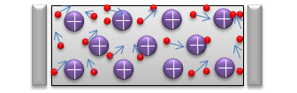 |
There are a lot of free electrons moving around randomly.
|
Electric Field Applied |
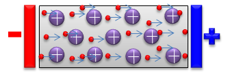 |
There are a lot of free electrons moving towards the positive charge and this movement of free electrons creates 'current'
|
|
Dielectric |
No Electric Field |
 |
Most of electrons are stay within the atom and stick around the positive nuclear.
|
Electric Field Applied |
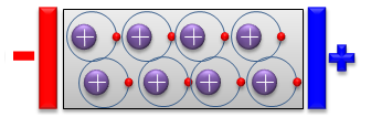 |
Electrons are attracted towards to positive electrode and positive nuclear are attracted toward negative electrode,but they does not go out of a certain boundary. This alignment create a dipole (di-electric) |
In the conductor rows, the red electrons are not tied to any nucleus. With a field applied they all drift toward the positive electrode, and that flow is a current. In the dielectric rows, each electron stays on its circle around its own nucleus. With a field applied, the electrons move to the side of the circle that faces the positive electrode, and the nuclei are pulled slightly the other way. Each atom becomes a small dipole, but no charge leaves the atom, so no current flows.
This small shift is called polarization, and it is the central effect of a dielectric. The dipoles create their own electric field, which points against the applied field. So the net field inside the material is weaker than it would be in vacuum. The dielectric constant in the next section measures exactly how much weaker.
A conductor has free electrons : an applied field moves them through the material, which is a current.A dielectric has bound electrons : an applied field only shifts them inside each atom, which is polarization.Polarization weakens the field inside the material : the induced dipoles point against the applied field.A dielectric is an insulator with a useful property : it blocks DC current, but it stores energy in its polarization, which is why capacitors, PCB substrates and coaxial cables use it.
Dielectric Constant
We briefly thought about intuitive meaning of 'Dielectric'. Now let's think of 'quantitive' aspect of 'Dielectric property'. We call the quantative aspect of 'Dielectric property' as Dielectric Constant. As shown below, Dielectric Constant is the relative permittivity with reference to the permitivity of Vacumm. (Unfortunately we have another terminology called 'permitivity'). Does it remind you of the nightmare in getting lost in the mingle of words when you try to figure out the meaning of a word in the dictionary. The dictionary explains on the word using other words which you don't understand... and if you look into that unknown words in the dictionary you would find another word that you don't understand.. and then you never get out of the loop. As far as I know, there is no clear solution for this kind of situation unfortunately.. you have to live with this -:)
One tip is .. just get the meaning out of the basic mathematical definition and try to apply it in more practical situation as much as possible.
The drawing below writes the definition as a ratio of two permittivities. The label under it gives the value of the vacuum permittivity.
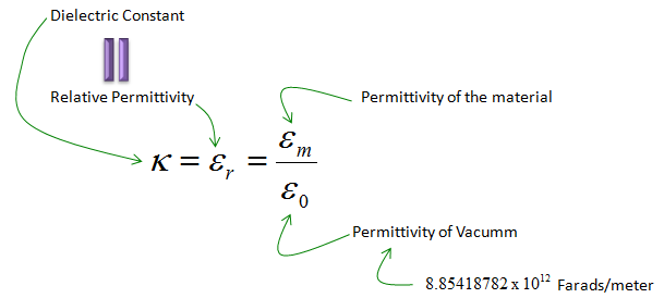
Figure 1. The dielectric constant is a ratio. It has no unit, and it compares the permittivity of a material with the permittivity of vacuum.
Dielectric constant and relative permittivity are two names for one number : the drawing writes it as κ = εr = εm / ε0.The exponent of ε0 is negative : the label reads 8.85418782 x 10¹² Farads/meter, but the value of ε0 is 8.85418782 x 10⁻¹² F/m. The minus sign is missing in the image.εr is never below 1 for ordinary materials : vacuum is the reference, so every material in the table at the end of this page has a value of 1 or more.
If we define the dielectric constant using the term 'Permitivity', it may not sound intuitive to many readers, but it may sound more familiar if we define it as follows. It defines Dielectric Constant using Capacitance. Suppose that you have two capacitance with exactly same dimension and same material for conductor plates. The only difference is the material filled in between the two conductor plates which makes the capacitor. In one capacitor, the space between the two plates is filled with vacume. In the other capacitor, the space between the two plates is filled with a dielectric material. And then you measure the capacitance of the two capacitors and you will get different values. If you take the ratio of the two measured capacitance (capacitance of the one with Vacume as denominator), it becomes the dielectric Constance of the material.
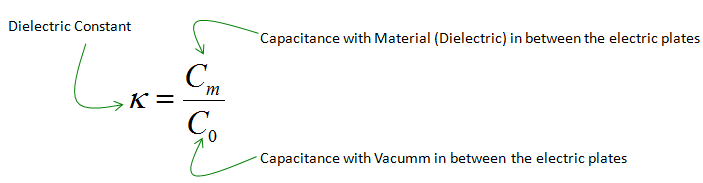
Figure 2. The same number defined by measurement. The ratio of two capacitances gives the dielectric constant without any reference to permittivity.
The two definitions agree because the capacitance of a parallel plate capacitor is C = ε0 εr A / d, where A is the plate area and d is the plate distance. Everything except εr is the same in the two capacitors, so the ratio Cm / C0 leaves only εr. This is also the basis of one common way to measure a dielectric constant.
Two definitions, one number : εm / ε0 and Cm / C0 give the same value.The capacitance ratio is the practical one : two capacitances can be measured with an ordinary capacitance meter.
Why we care about Dielectric Constant ?
If you are still not clear about the definition of the Dielectric Constant, just hold it on there and just try to understand how it affects physical characteristics that you are familiar with. As you see more and more of those examples, you would get stronger motivation to understand the definition and get back to what is described above. Then, the definition parts would come to you with more intimate face.
Each of the sub-sections below takes one physical quantity and shows how the dielectric constant enters its formula. Keep an eye on the power of εr in each case. Force and capacitance change with εr itself, while wavelength, speed and impedance change with its square root.
Effect on Electric Force
This example shows how Dielectric Constant influece the force between two electric charges. As you might have learned from your high school physics, the strength of Force is proportional to the multiplication of amount of two charges. and the strength of Force is in inversally protportional to the "distance squared" between the charges.
Also the force is inversally proportional to the permitivity of the material between two charges.
The illustration and equation on the left side is the case where there is no other material between the two charges. You can also say that the material between the two charges is vacume.
The illustration and equation on the right side is the case where there is a dielectric material between the two charges. As you see in the equation, the Force between charges is in inversely proportional to the permitivity of the dielectric material. It means that as the permitivity of the dielectric material goes higher, the force between charges gets smaller.
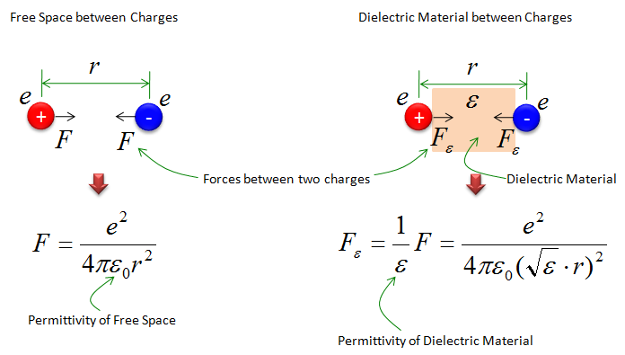
Figure 3. A dielectric between two charges divides the force by εr. The same charges at the same distance attract each other less.
The ε on the right side is the relative permittivity : the label calls it the permittivity of the dielectric material, but in Fε = F / ε it has to be the unitless εr. The absolute permittivity of the material is ε0 εr, which is the product in the denominator.The dielectric acts like a longer distance : the right-hand formula writes the distance as √ε x r. So a material with εr = 4 gives the same force as vacuum at twice the distance.Water weakens the force strongly : with εr = 88 from the table at the end of this page, the force between two charges in cold water is 1/88 of the force in vacuum. This is one reason why water separates ionic compounds so well.
Effect on Capacitance
Now let's look into another example. This is about the capacitance. The equation (formular) shown below tells about the comparizon of a capacitance with no material (vacume) and the one with dielectric material between two electric plates.
The formula below tells "The larger the dielectric constants of the material in the capacitor is, the larger the capacitance becomes".
For example, if you put a dielectric material with larger dielectric constant between the two plates when you make a capacitor, you would get a capacitor with larger capacitance value.

Figure 4. The dielectric constant multiplies the capacitance. The geometry sets C0, and the material scales it.
Let's put numbers on it. Take two plates of 1 cm2 each, 1 mm apart. With vacuum between them, C0 = 8.854 x 10-12 x 10-4 / 10-3 F = 0.885 pF. With PTFE, εr = 2.1, the same plates give 1.86 pF, and with FR-4, εr = 4.8, they give 4.25 pF. The same holds for every trace and pad on a circuit board, which is why the substrate material changes the parasitic capacitance of a layout.
Effect on Wavelength
If most of RF and Microwave engineers, this would be the most practical example. Following is the equation defining the wavelenth from the frequency and speed of light. The first part is the definition you are familiar from High school physics which assume that the wave propagate through vacume.
When the electromagnetic wave propagate through a diectric material, the wavelength is in inversely proportional to the square root of relative mermitivity (Dielectric constant). It means that as dielectric constant gets larger, wavelength gets shorter. It also mean that dielectric constant can influence the size of the RF/Microwave devices which are influenced by wavelength.
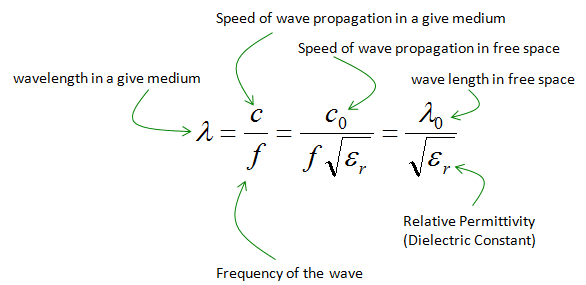
Figure 5. A wave in a dielectric is slower by √εr, so at the same frequency its wavelength is shorter by the same factor.
Here is a concrete case at 3.5 GHz. In free space the wavelength is 85.7 mm. In PTFE it is 85.7 / √2.1 = 59.1 mm, and in FR-4 it is 85.7 / √4.8 = 39.1 mm. A quarter-wave line or a patch antenna on FR-4 is therefore less than half as long as the same structure in air. On a microstrip line, part of the field runs in the air above the board. So the effective dielectric constant of the line lies between 1 and the εr of the substrate, and the real wavelength lies between the two values above.
Effect on Propagation Speed and Impedance
The wavelength formula hides two more effects that an RF engineer meets every day. The first is speed, because the wave moves at c0 / √εr. The second is impedance, because a transmission line stores energy in its dielectric.
The ratio 1 / √εr is called the velocity factor of a cable. For PTFE it is 1 / √2.1 = 0.69. So a signal needs 3.34 ns to cross 1 m of air line, but 4.83 ns to cross 1 m of PTFE cable. This delay matters whenever two cable paths have to arrive in phase.
The characteristic impedance of a coaxial line is Z0 = (60 / √εr) x ln(D / d), where D and d are the outer and inner conductor diameters. A higher εr lowers Z0, so a 50 ohm line with PTFE needs a larger D/d ratio than a 50 ohm line with air. The Connectors page works through this and shows how it limits the size and the frequency of a connector.
Force and capacitance scale with εr : the force is divided by εr and the capacitance is multiplied by εr.Wavelength and speed scale with √εr : at 3.5 GHz the wavelength shrinks from 85.7 mm in air to 39.1 mm in FR-4.Impedance also scales with 1 / √εr : for the same geometry, a line filled with a dielectric has a lower Z0 than an air line.A higher εr means a smaller circuit : that is useful for size, but it also means tighter tolerances, because every millimeter is a larger part of a wavelength.
Dielectric Constants for well known Materials
The formulas above only become useful once you know the value of εr for a real material. The values below run from 1 for vacuum to 88 for cold water. So the choice of material alone can change a wavelength by a factor of more than nine, because √88 = 9.4.
Following is a list of dielectri material which are widely used in electric device and RF/Microwave device manufacturing.
|
Material |
Dielectric Constant |
|---|---|
|
Vacuum |
1.0 |
|
Air |
1.0006 |
|
Teflon(PTFE : Polytetrafluoroethylene) |
2.1 |
|
Rubber |
2.8 |
|
Paper |
3.0 |
|
Cocaine |
3.1 |
|
Mica |
3 ~ 6 |
|
Quartz |
4.2 |
|
FR-4 |
4.8 |
|
Glass |
7.8 (5~10) |
|
Zircon |
12 |
|
Ethyl Alcohol |
24 |
|
Water (212 deg F) |
55.3 |
|
Water (32 deg F) |
88 |
Read the table as typical values, not as fixed constants. The dielectric constant of a real material depends on frequency and temperature. The two water rows show the temperature effect directly: 88 at 32 deg F and 55.3 at 212 deg F. For board materials such as FR-4, the value also varies between manufacturers and between laminates, so a design at GHz frequencies uses the value from the datasheet of the actual laminate.
A second property does not appear in the table at all, and it matters just as much at RF. A real dielectric also absorbs part of the energy that passes through it. This loss is written as the loss tangent, tan δ, which is the ratio of the imaginary part to the real part of the complex permittivity. PTFE is popular in RF cables and connectors because it combines a low dielectric constant with a low loss.
Air is almost vacuum : its dielectric constant of 1.0006 is so close to 1 that most RF calculations treat air as vacuum.PTFE and FR-4 are the two most common RF materials : PTFE at 2.1 for cables, connectors and high-frequency boards, and FR-4 at about 4.8 for ordinary circuit boards.Water has a very high dielectric constant : so humidity and moisture inside a material raise its effective dielectric constant.Loss is a separate number : the table gives only the dielectric constant. Check the loss tangent before you choose a material for an RF path.