When you look at the output of an RF component on a spectrum analyzer, you usually see more tones than you put in. Some of them are harmonics and some of them are spurs, and the two names are not interchangeable. I'll first separate the two by where they sit in frequency and by where they come from. Then we look at when each of them is a problem and when it is useful.
- What is the difference between Harmonics and Spurious ?
- Is harmonics always bad ?
- Is Spurious always bad ?
- Reference
What is the difference between Harmonics and Spurious ?
Both harmonics and spurs are unwanted output frequencies, so let's start with the one property that separates them. That property is the position of the tone relative to the input frequency.
If you put a signal (the red arrow shown below) to any RF component, you would see some other output frequencies. In ideal devices, you should not get these additional frequencies (except in case of Mixer), but in real devices you would get some degree of those additional frequencies. If you look closely at those frequecies, you would get two different types. One type of them would happen at the exact multiples of the input frequency and this is called 'Harmonics' (as shown in green arrow). The other type of them would happen not at the multiplication of the input frequency and these are called 'Spurious'.
The picture below is a sketch of an output spectrum. The horizontal axis is frequency, marked at f0 to 5f0, and the vertical axis is the level of each tone. The labels "Harmonics" and "Spurious" point to the two groups of unwanted tones.
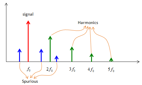
Figure 1. Harmonics and spurs in one output spectrum. Harmonics sit exactly on multiples of f0, and spurs sit anywhere else.
- The red arrow at f0 is the input signal, and it is the tallest tone.
- The green arrows at 2f0, 3f0, 4f0 and 5f0 are the harmonics. In Figure 1 they become smaller as the order goes up.
- The blue arrows are the spurs. One sits below f0, one sits between f0 and 2f0, and one sits just above 2f0. None of them is on a multiple of f0.
Now let's see where the harmonics come from. A real amplifier is not perfectly linear, so we can write its output as y = a1x + a2x2 + a3x3. Put in a single tone x = A cos(ωt). The square term gives a2A2/2 at DC and a2A2/2 at 2ω. The cube term gives 3a3A3/4 at ω and a3A3/4 at 3ω. So an xn term creates the n-th harmonic, and the harmonic is always an exact multiple of the input frequency.
The same math also tells you how fast the harmonics grow. The second harmonic is proportional to A2, so it rises by 2 dB for every 1 dB of input. The third harmonic rises by 3 dB per dB. The fundamental rises by only 1 dB per dB, so in dBc the second harmonic grows by 1 dB per dB and the third by 2 dB per dB. For example, a second harmonic at -40 dBc becomes -37 dBc when you raise the input by 3 dB.
Spurs need a second ingredient, which is another frequency inside the device. Typical sources are the LO of a mixer, a clock, the reference of a PLL, or a second carrier. A nonlinear stage mixes that frequency with the signal, and the products fall at sums and differences of the two. These products are not multiples of f0, so they appear as spurs.
Harmonics sit exactly at multiples of the input frequency : the n-th harmonic comes from the xn term of the nonlinearity.Harmonics grow faster than the signal : in dBc, the second harmonic rises by 1 dB and the third by 2 dB for each dB of input.Spurs sit at any other frequency : they come from mixing with a second frequency such as an LO, a clock or a PLL reference.You can predict the frequency of both : you need f0 for harmonics, and f0 plus the other frequencies in the device for spurs.
Is harmonics always bad ?
Harmonics are unwanted in most transmitters, but a whole class of circuits is built to produce them. So the right question is whether a harmonic lands where it hurts something. Let's look at one useful case and one harmful case.
: In most case, you would think it is bad because they are not what you wanted to have. But in some case, you may want to have a certain type of harmonics. For example, in some resonator application, there are some cases where we want to use a harmonics to get higher resonance frequency.
A frequency multiplier is the clearest useful case. It drives a nonlinear device hard on purpose, and then a filter keeps only one harmonic. A doubler keeps 2f0, and a tripler keeps 3f0. This is a common way to build a high frequency source from a stable low frequency oscillator.
The harmful case appears when a harmonic of the transmitter lands in a band that the same device, or another device nearby, is receiving. Let's take LTE Band 3 as an example. Its uplink runs from 1710 MHz to 1785 MHz, so the second harmonic of that uplink runs from 3420 MHz to 3570 MHz. That range lies inside NR band n78, which runs from 3300 MHz to 3800 MHz. So in EN-DC with Band 3 and n78, the second harmonic of the LTE uplink can fall on the n78 downlink of the same phone. Also, 3GPP limits harmonics like any other emission. They fall under the spurious emission requirements, which the next section explains.
The usual fix is a filter after the PA. A low pass filter passes f0 and attenuates 2f0 and above. Linearity also helps, because a smaller a2 and a3 produce smaller harmonics at the same output power.
A frequency multiplier uses harmonics on purpose : it keeps one harmonic with a filter and rejects the rest.A harmonic hurts when it lands in a receive band : 2 x 1710 to 1785 MHz gives 3420 to 3570 MHz, inside n78.A low pass filter after the PA removes most of the harmonic energy : the harmonics are far from f0, so a simple filter separates them.Lower drive reduces harmonics quickly : in dBc, the harmonics fall faster than the fundamental when the input goes down.
Is Spurious always bad ?
A mixer is the case that makes this question interesting, because its wanted output is itself a new frequency. We also need to check how 3GPP uses the word spurious, because it does not follow the split in Figure 1.
: In most case, you would think it is bad because they are not what you wanted to have. But in some case, you may want to have a certain type of spurious. For example, in most of Mixer the output frequency is not same as any of the input frequencies and in most case the output frequencies are not at the harmonic point of any input frequency. So by definition, the output of mixer are a kind of spurious, but these are not bad spurious.
Let's put numbers on the mixer case. Take an RF input at 1900 MHz and an LO at 1700 MHz. The wanted output is the difference, 200 MHz. But the mixer also produces the sum at 3600 MHz, and it produces higher order products at m x fRF + n x fLO for other integers m and n. For example, 2 x 1700 - 1900 gives 1500 MHz, and 2 x 1900 - 2 x 1700 gives 400 MHz. Only 200 MHz is wanted. The other products are spurs in the bad sense, and the filter after the mixer has to remove them.
3GPP uses the word in a wider sense. 36.101 defines spurious emissions as emissions caused by unwanted transmitter effects such as harmonics emission, parasitic emissions, intermodulation products and frequency conversion products. So in a 3GPP requirement, a harmonic counts as a spurious emission. The requirement applies outside the out of band domain, which ends FOOB away from the edge of the channel bandwidth. FOOB is 25 MHz for a 20 MHz LTE channel. The general UE limits are in the table below.
Frequency range |
Maximum level |
Measurement bandwidth |
9 kHz to 150 kHz |
-36 dBm |
1 kHz |
150 kHz to 30 MHz |
-36 dBm |
10 kHz |
30 MHz to 1000 MHz |
-36 dBm |
100 kHz |
1 GHz to 12.75 GHz |
-30 dBm |
1 MHz |
The table is a short form of 36.101 Table 6.6.3.1-2. The full table adds rows above 12.75 GHz that apply only to some bands. When you read these limits, keep the measurement bandwidth in mind. A limit of -30 dBm in 1 MHz is not the same as -30 dBm in 100 kHz, so a spur measured with a different bandwidth has to be converted first.
The wanted output of a mixer is a new frequency : by the definition in Figure 1 it is a spur, but the design needs it.A mixer also creates unwanted products at m x fRF + n x fLO : with 1900 MHz and 1700 MHz, these include 3600, 1500 and 400 MHz.In 3GPP, spurious emissions include harmonics : 36.101 lists harmonics, parasitic emissions, intermodulation and frequency conversion products together.A spurious limit always comes with a measurement bandwidth : compare a measured spur with the limit only in the same bandwidth.