A direct conversion receiver removes the whole IF stage, and that reduction in parts is its main attraction. The price for fewer parts is a set of problems that appear right at DC, where the wanted signal now sits. I'll first go through the block diagram and why it needs an I path and a Q path. Then we look at each known problem and its usual solution.
How does a direct conversion receiver work ?
A conventional receiver converts the signal in two steps, first to an IF and then to baseband. Let's see what changes when the LO sits exactly on the carrier and one step does the whole job.
Homodyne, Zero IF and Direct Conversion are all referring to a same thing. In this method, the signal get converted directly from RF to baseband and baseband to RF. That's why it is called 'Direct Conversion'. There used to be technical issues (e.g, DC offset or noise removal) and it is hard to do direct conversion when the RF frequency is very high. But the benefit for this system would be obvious. Less component, less cost and probably/hopefully less trouble for tuning components.
The block diagram below follows the receive path from the antenna to the two ADCs. After the LNA the signal splits into two mixers. Both mixers use the same LO, but the lower one gets it through a 90 deg phase shifter. Small spectrum sketches show the signal at fc before the mixers and centred on DC after the LP filters. Three thought bubbles, (A), (B) and (C), ask where problems can appear.
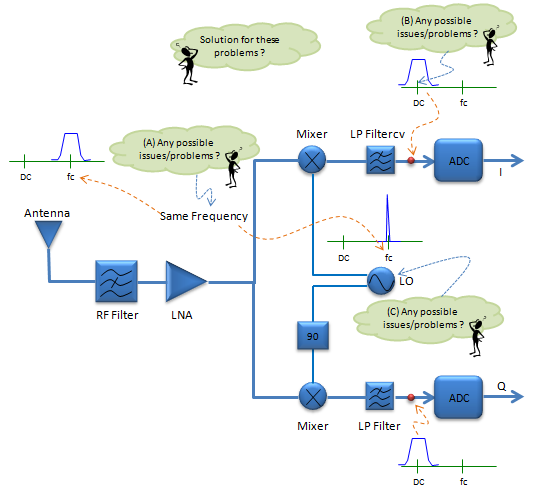
Figure 1. Direct conversion receiver. The LO frequency equals the signal frequency fc, so the mixers move the signal straight to DC.
- The receive chain starts with the Antenna, the RF Filter and the LNA. These are the same as in any other receiver.
- The upper Mixer takes the LO directly and produces I. The lower Mixer takes the LO through the block marked 90 and produces Q.
- The label "Same Frequency" joins the signal spectrum at fc with the LO spectrum at fc. This is what makes the architecture zero IF.
- After each LP Filter the spectrum sketch is centred on DC. The ADC then samples the baseband signal directly.
- Bubble (A) sits at the LO and signal pair, bubble (B) at the output of the upper LP Filter, and bubble (C) at the LO. The next section goes through the issues these bubbles ask about.
Now let's see why the receiver needs two mixers. Write the received signal as r(t) = Re{s(t) ejωct}, where s(t) = I(t) + jQ(t) is the complex baseband signal. Multiply r(t) by cos(ωct) and low pass filter the result, and you get I(t)/2. Multiply by -sin(ωct) instead, and you get Q(t)/2. A single mixer would give only one of the two. The parts of the spectrum above and below fc would then fold onto each other at DC, and the receiver could not separate them. The 90 deg branch keeps the two halves apart.
This structure also sets the bandwidth of the LP filters. Each filter needs only half of the channel bandwidth, because the signal now spans from -BW/2 to +BW/2 around DC. For a 20 MHz channel, each LP filter passes about 10 MHz. The same filters also do the channel selection, which a superheterodyne receiver does with an IF filter. There is also no image frequency to reject in the usual sense, because the IF is zero. The image of the signal is the signal itself, mirrored around DC.
The LO sits on the carrier : the mixers move the signal from fc straight to DC, with no IF stage.Two mixers in quadrature are required : cos(ωct) gives I and -sin(ωct) gives Q, so the two halves of the spectrum stay separate.The baseband LP filters do the channel selection : each one needs half the channel bandwidth, for example 10 MHz for a 20 MHz channel.Fewer parts is the main benefit : there is no IF filter and no second LO.
Possible Issues and Solutions
Every problem in the list below comes from the same fact. The LO and the wanted signal share one frequency, and the wanted signal ends up at DC. Let's go through the list first and then put numbers on each item.
i) Since signal frequency and LO frequency is same, engergy from LO can interfere with received or transmitted signal.
--> Possible solution : Increase LO frequency twice as signal frequency and use frequency divider (1/2) between LO and mixer.
ii) Even a small differnece between signal frequency and LO frequecy can directly influence the downconverted signal (baseband signal) which would cause BER.
--> Use AFC (Automatic Frequency Control) to dynamically tune the LO frequency to catch up signal frequency.
iii) Downconverted signal may contain baseband DC component (DC offset) which may de-sensitize the baseband demodulator.
--> Use DC Notch filter after the mix.
Item i) fits bubble (A) in Figure 1. The LO runs at fc, so any LO power that leaks toward the antenna lands inside the receive band. Some of that leakage comes back into the mixer and mixes with the LO itself. The product is a DC voltage, which is one source of the DC offset in item iii). The divider solution works because the oscillator then runs at 2fc. For example, for a 2 GHz carrier the VCO runs at 4 GHz, and only the divided 2 GHz signal exists near the mixer.
Item ii) fits bubble (C). Let's size the error. A 1 ppm error at 2 GHz is 2 kHz. After the mixer, the constellation keeps rotating at 2 kHz. In an OFDM system with 15 kHz subcarrier spacing, one useful symbol lasts about 66.7 microseconds, so the constellation turns by 48 deg within one symbol. The offset is also 13 percent of the subcarrier spacing, which causes inter-carrier interference. This is why the AFC loop must keep the residual error to a small fraction of the subcarrier spacing.
Item iii) fits bubble (B), at the output of the LP Filter. A DC offset can be much larger than the wanted signal, so it can saturate the baseband stages or the ADC. Flicker noise, which rises toward DC, adds to the problem. The DC notch removes the offset and the flicker noise closest to DC, but it also removes any part of the wanted signal that sits near DC. So the notch has to be narrow compared with the signal bandwidth.
One more issue belongs on this list, the mismatch between the I path and the Q path. When the gains differ by 1 dB and the LO phases are 5 deg away from 90 deg, the signal and its mirror around DC separate by only about 22.8 dB. So the mirrored part of the signal falls on top of the wanted part, and it limits the EVM. Receivers therefore calibrate the gain and the phase of the two paths. The Image / Image Rejection page explains image rejection in more detail.
LO leakage turns into DC offset : leaked LO power mixes with the LO itself and produces a DC voltage.Running the VCO at 2fc keeps it away from the receive band : a divider by 2 makes the LO at fc only where the mixer needs it.A small frequency error is large at baseband : 1 ppm at 2 GHz is 2 kHz, or 48 deg of rotation per 66.7 microsecond symbol.A DC notch must be narrow : it removes the offset and the flicker noise closest to DC, but also any signal energy near DC.I/Q mismatch mirrors the signal onto itself : 1 dB and 5 deg of mismatch leave only about 22.8 dB of image rejection.