Simply put, Link budget is a kind of balance sheet from a source to a destination in terms of power loss and gain. It starts from the transmit power, adds every gain, subtracts every loss along the path, and ends with the power that reaches the receiver.
Every radio link, from a cable run to a satellite hop, is planned with this balance sheet. Let's first add up a chain of gains and losses. Then we will see why the numbers can simply be added, where the big path loss number comes from, and how to decide whether the received power is enough.
- How do gains and losses add up from a to h ?
- Why can we simply add the numbers ?
- What sets the path loss of block F ?
- How much received power is enough ?
How do gains and losses add up from a to h ?
Every component can fall into one of the two categories in terms of input/output energy balances. Some devices cause energy loss (power loss) as a signal goes through (these devices are called passive device) and some devices produce energy gain as a signal goes through (these devices are called active device. Be careful, even these devices cannot create any new energy. It is against the law of physics. They are pulling some energy from somewhere else and add it to the signal).
Suppose you have multiple devices connected together as shown below and some are activce and some are passive. What would be the sum of the energy balance between the start (point a) and end (point h) ?
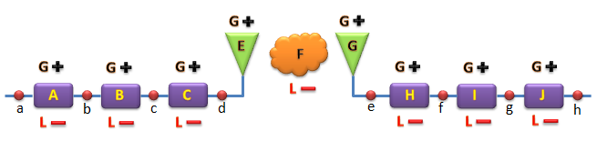
Figure 1. A generic link from point a to point h. Each block can add gain or cause loss, and the two antennas E and G sit on either side of the air path F.
As more specific example, let's assume that you have following components connected together and engergy gain or loss for each specific block is as follows. What would be the total energy balance ?
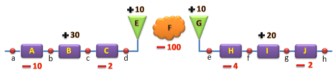
Figure 2. The same chain with a value in dB on every block. The air path F dominates with -100 dB.
This 'total energy balance' in this question is called 'Link Budget' and it can be calculated as follows. (Math is very simple)

Figure 3. The link budget from a to h is the plain sum of the block values, -48 dB.
Let's read the chain in Figure 2 from left to right. Block A loses 10 dB, and block B is an amplifier that adds 30 dB. Block C loses 2 dB, which could be a cable to the antenna. The transmit antenna E and the receive antenna G each add 10 dB, and the air path F between them loses 100 dB. On the receive side, H loses 4 dB, the amplifier I adds 20 dB, and J loses 2 dB. The numbers in Figures 2 and 3 have no unit written on them, but they are dB values, which is why a plain sum works.
For practical tutorial, refer to Lecture on Link budget (YouTube)
A link budget is a sum of gains and losses in dB : gains get a plus sign, and losses get a minus sign.Active devices add gain, passive devices cause loss : the amplifiers B and I are active, and the cables and filters are passive.The air path usually dominates : in Figure 2, block F alone is larger than all the other blocks together.
Why can we simply add the numbers ?
In linear terms, each block multiplies the power by a factor. A chain of nine blocks means nine multiplications, with factors from 1000 down to 0.0000000001. The dB scale turns every multiplication into an addition, because log(a x b) = log a + log b. That is the only reason a link budget can be done with a plain sum.
We can check the -48 dB of Figure 3 in linear terms. The factor 10-48/10 is 1.58 x 10⁻⁵. So if 100 mW enters at point a, only 0.00158 mW, or 1.58 microwatts, leaves at point h. The same result in dBm is 20 dBm - 48 dB = -28 dBm.
This also shows the rule for units. A gain or a loss is a ratio, and its unit is dB. A power level is absolute, and its unit is dBm, which means dB relative to 1 mW. You add dB to dBm and get dBm. You never add two dBm values, because two power levels do not add in the log domain. For example, 0 dBm plus 0 dBm of uncorrelated power is 2 mW, which is 3 dBm, not 0 dBm and not "0 + 0". See dB, dBm, dBc.
dB turns products into sums : this is why a link budget is a column of plus and minus numbers.dB is a ratio, dBm is a power level : a link budget starts from a level in dBm and adds ratios in dB.-48 dB is a factor of 1.58 x 10⁻⁵ : 100 mW, or 20 dBm, at a becomes -28 dBm at h.
What sets the path loss of block F ?
Block F carries the largest number in the budget, so it deserves a closer look. In free space, the loss between two isotropic antennas depends only on the distance d and the wavelength λ. The antenna gains are separate entries, which is why E and G are their own blocks in Figure 2.
The free space path loss is FSPL = 20 log10(4πd/λ) in dB. It grows by 6 dB every time the distance doubles, and by 6 dB every time the frequency doubles. The table below gives a few values.
Frequency |
100 m |
1 km |
10 km |
700 MHz |
69.3 dB |
89.3 dB |
109.3 dB |
2 GHz |
78.5 dB |
98.5 dB |
118.5 dB |
3.5 GHz |
83.3 dB |
103.3 dB |
123.3 dB |
28 GHz |
101.4 dB |
121.4 dB |
141.4 dB |
So the -100 dB of block F matches a free space link of about 1.19 km at 2 GHz, or about 680 m at 3.5 GHz. A real link is rarely free space. Buildings, trees, walls and the human body add more loss, and shadowing makes the loss vary from place to place. Planners therefore use propagation models for the path loss and keep a margin for the variation. See Friis' Transmission Equation for the derivation.
Free space loss is 20 log10(4πd/λ) : it assumes isotropic antennas, so antenna gains are added separately.Double the distance or the frequency and you lose 6 dB more : so 28 GHz has about 23 dB more free space loss than 2 GHz over the same distance.Free space is the best case : obstacles, penetration and shadowing add loss on top of it.
How much received power is enough ?
A link budget ends with a received power, but a number such as -48 dBm is not useful on its own. We need to compare it with the lowest power the receiver can still decode. That lowest power is the sensitivity, and the difference between the two is the link margin.
Sensitivity starts from thermal noise. At 290 K, the noise power density is kT = -174 dBm/Hz. Over a bandwidth B, the noise floor is -174 + 10 log10(B) dBm. The receiver adds its own noise figure NF, and the demodulator needs a minimum SNR. So the sensitivity is -174 + 10 log10(B) + NF + SNRmin.
Let's put numbers in. For a 10 MHz channel, 10 log10(107) = 70, so the noise floor is -104 dBm. With a 7 dB noise figure and an SNR of 0 dB, the sensitivity is -97 dBm. Now feed 0 dBm into point a of Figure 2. The received power at h is then -48 dBm, and the margin is -48 - (-97) = 49 dB. In other words, block F could lose up to 149 dB instead of 100 dB before this link stops working.
A real design does not spend all of that margin on distance. Part of it is kept as a fade margin, because the received power changes with shadowing and fast fading. The margin you need depends on how reliable the link must be. See Sensitivity and Noise Figure.
Sensitivity = -174 + 10 log10(B) + NF + SNRmin : every term is in dB or dBm.Margin = received power - sensitivity : a positive margin means the link closes.Keep part of the margin for fading : the path loss of a real link changes with location and time.