If you are not working in the area of RF circuit design, you might have not heard of this term 'Loss Tagent'. It doesn't mean that you don't have this property in any other types of circuit. I mean we can ignore these property in any other circuit types (e.g, DC circuit or low frequency AC circuit etc).
Let's suppose we want to make a capacitor or design a capacitive circuit (e.g, using Microstrip). What you want to get would be definitely to have a capacitor that has property of 100 % of capacitance (charge storage capability or energy storage capability), but in reality the component would have some resistance property which would cause energy loss. 'Loss Tangent' is an indicator to show how much 'unwanted resistance property (energy loss factors)' exists in a component. Simply put, it indicates the ratio of Capacitance portion (energy storage) and resistance (engery loss) portion of a component.
The loss tangent is written tan δ. It is a property of the dielectric material rather than of one component. So the same number applies to a capacitor, a PCB substrate and the insulation of a coaxial cable. The value also depends on frequency, as the table on this page shows. The sections below explain where the name comes from, list typical values, and show how the number turns into a loss in dB.
- Why is it called a tangent ?
- Loss Tangent Value for Common Materials
- How does loss tangent turn into loss in dB ?
Why is it called a tangent ?
The name comes from a right triangle. The energy loss and the energy storage of a component form two sides of that triangle. The ratio of two sides of a right triangle is the tangent of one of its angles. The steps below build this triangle from the equivalent circuit of the material.
Yes.. now I understand 'Loss' part of the term.. then what is the meaning of 'tangent' part ?
I think it would be easier to use a simple high school math than trying to explain in plain language. As you learned in Impedance page, the capacitance part and resistance part of the component can be represented in single entity in a coordinate as illustrated below. If you take the 'Tangent' angle between the capacitance part and resistance part, it became the ratio of Capacitance portion (energy storage) and resistance (engery loss) portion of a component. That's why we call this ratio as 'Loss Tangent'.
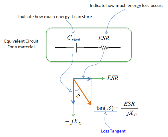
Series equivalent circuit of a lossy dielectric. The loss tangent is the ratio of the resistive part to the reactive part.
- The equivalent circuit puts Cideal, labelled as how much energy it can store, in series with ESR, labelled as how much energy loss occurs.
- In the vector diagram, ESR points to the right and -jXC points down. The orange vector is their sum, and δ is the angle between it and the -jXC axis.
- The formula at the lower right, labelled Loss Tangent, reads tan(δ) = ESR / -jXC.
One detail of that formula needs care. The tangent is a ratio of two real lengths, so it uses the magnitude of the reactance: tan δ = ESR / XC = 2π f C x ESR. The -j in the drawing only marks the direction of the reactance axis. For example, a 10 pF capacitor at 1 GHz has XC = 15.9 ohm. With tan δ = 0.001, its ESR is 0.016 ohm. The inverse of the loss tangent is the quality factor of the capacitor, Q = 1 / tan δ = XC / ESR. In this example Q is 1000.
tan δ compares loss with storage : it is ESR / XC, so a smaller value means a better dielectric.δ is an angle in the impedance plane : it is the angle between the ideal capacitive reactance and the actual impedance, and a lossless material has δ = 0.The loss tangent is the inverse of Q : tan δ = 0.001 means a capacitor Q of 1000.
Loss Tangent Value for Common Materials
The table below lists tan δ at two frequencies, 100 MHz and 3 GHz. Read the two columns together, because the value of one material can change a lot between them. These are typical values for the bulk material. A commercial PCB substrate states its own value in its datasheet, usually at a named test frequency.
|
Material |
Loss Tan #1 |
Loss Tan #2 |
|
Air |
0.0 @100 MHz |
0.0 @3 GHz |
|
PTFE |
2E-4 @100 MHz |
15E-4 @3 GHz |
|
PolyEthylene, DE-3401 |
2E-4 @100 MHz |
3.1E-4 @3 GHz |
|
Polyolefin, irradiated |
3E-4 @100 MHz |
3E-4 @3 GHz |
|
Polystyrene |
1E-4 @100 MHz |
3.3E-4 @3 GHz |
|
Polyvinal formal (Formvar) |
1.3E-2 @100 MHz |
1.1E-2 @3 GHz |
|
Nylon |
2E-2 @100 MHz |
1.2E-2 @3 GHz |
|
Quartz, fused |
2E-4 @100 MHz |
6E-5 @3 GHz |
|
Pyrex Glass |
3E-3 @100 MHz |
5.4E-3 @3 GHz |
|
Water, distilled |
5E-3 @100 MHz |
1.6E-1 @3 GHz |
Three things stand out in the table. The first is the range. The plastics at 3 GHz sit near 3E-4, while distilled water reaches 1.6E-1, which is about 500 times larger. The second is that the frequency trend differs between materials. Polystyrene and Pyrex Glass become lossier at 3 GHz, while fused quartz and Nylon become less lossy. The third is water. Its value rises 32 times from 100 MHz to 3 GHz. This is why moisture absorbed by a substrate raises its loss at microwave frequencies.
Air is the lossless reference : its loss tangent is 0 at both frequencies.Low-loss plastics sit near 3E-4 at 3 GHz : polyethylene, irradiated polyolefin and polystyrene all fall in this range.Read the value at the operating frequency : a value from 100 MHz can be wrong by a large factor at 3 GHz.Water is very lossy at microwave frequencies : 1.6E-1 at 3 GHz, so moisture in a material raises its loss.
How does loss tangent turn into loss in dB ?
The loss tangent alone does not tell you how many dB a line loses. Let's convert it for the simplest case. This is a TEM line whose field sits entirely inside the dielectric, such as a coaxial cable.
The dielectric attenuation of such a line is αd = π f √εr tan δ / c in Np/m. Here c is the speed of light in vacuum, and one neper is 8.686 dB. A simpler form follows when you count the length in wavelengths inside the dielectric. That wavelength is λ = c / (f √εr). So the loss per wavelength is π tan δ Np, or 27.3 x tan δ dB. This form does not depend on εr.
Let's apply it to the table at 3 GHz. Polyethylene with tan δ = 3.1E-4 loses 0.0085 dB per wavelength. Nylon with 1.2E-2 loses 0.33 dB per wavelength. Distilled water with 1.6E-1 loses 4.4 dB per wavelength. Now assume εr = 2.25 for polyethylene. One metre of line at 3 GHz is then 15 wavelengths long, and its dielectric loss is 0.13 dB per metre.
Two limits apply to this simple form. First, it covers only the dielectric loss. The conductor loss of the metal adds to it, and it usually dominates at lower frequencies when the dielectric is a low-loss one. Second, on a microstrip line part of the field runs in the air above the substrate. So only a part of the field sees the loss tangent of the substrate. The Microstrip page covers that geometry.
The loss per wavelength is 27.3 x tan δ dB : this holds for a TEM line filled with the dielectric, whatever its εr.The loss per metre grows with frequency : for a constant tan δ, αd is proportional to f, because a metre holds more wavelengths.Conductor loss adds to the dielectric loss : and on a microstrip line only part of the field sees the substrate.