Near field and far field is determined with reference to the wave length of the signal. The distance from transmitter/reciever less than the wavelength is considerted to be near field. The distance from transmitter/reciever greater than two wavelengths is considerted to be far field, and the region between one and two wavelengths is a transition.
This rule of thumb fits a small antenna, such as a dipole in a handset. A large antenna needs a longer distance before its far field begins. So this page places the boundaries first, and then describes how the fields behave in each region. After that it shows how the size of the antenna moves the far field boundary, and why the distinction matters when you measure an antenna or a device over the air.
- Where are the near field and far field boundaries ?
- How do the fields behave in each region ?
- How does antenna size move the far field boundary ?
- Why does the distinction matter in RF testing ?
Where are the near field and far field boundaries ?
Let's start with the space around one transmitting antenna and ask where its behavior changes. Close to the antenna the fields are dominated by energy that stays attached to the antenna. Far from it, only a travelling wave is left. The boundaries between these zones are set by the wavelength, and for a large antenna also by its size.
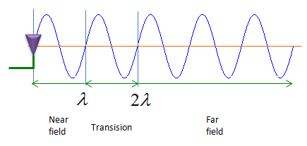
- The antenna sits at the left edge, and the blue sine wave travels away from it to the right.
- The green arrows split the distance into three zones: Near field up to λ, Transision from λ to 2λ, and Far field beyond 2λ.
- The wave looks the same in all three zones. The drawing marks distance only, because the difference between the zones is in the field structure, not in the shape of the wave.
Textbooks name the same zones in a more detailed way. The reactive near field is closest to the antenna. For a small antenna it extends to about λ/2π, which is 0.16 λ. Beyond it lies the radiating near field, also called the Fresnel region. The far field, also called the Fraunhofer region, is the zone where the radiation pattern no longer changes with distance. The boundaries are not sharp. The field changes gradually from one behavior to the next, which is why the picture shows a transition zone rather than a single line.
The wavelength sets the scale : for a small antenna the near field ends at about one wavelength and the far field starts at about two wavelengths.The reactive near field is the innermost zone : for a small antenna it reaches only about λ/2π from the antenna.The boundaries are gradual : rules of thumb give a distance where one behavior dominates, not a line where it switches.
How do the fields behave in each region ?
Why do engineers care which zone they are in? The answer is that the relation between the electric field E and the magnetic field H is different in each zone. So a measurement that is correct in one zone can be wrong in another.
Let's take the simplest radiator, a short dipole. Its fields contain three kinds of terms. One term falls as 1/r, one as 1/r2 and one as 1/r3, where r is the distance from the antenna. The 1/r2 and 1/r3 terms describe energy that flows out and back into the antenna in every cycle. They store energy, like the field of a capacitor or an inductor, and they carry no net power away. The 1/r term is the radiated wave. All three terms have the same size at r = λ/2π. Closer than that, the storage terms dominate. Further out, they fade much faster than the 1/r term, and only the radiated wave remains.
In the far field the wave has a simple structure. E and H are perpendicular to each other and to the direction of travel, and they are in phase. Their ratio is the wave impedance of free space, 120π or about 377 ohm. The power density falls as 1/r2, which is the basis of the free space path loss formula. In the near field none of this holds. The ratio of E to H depends on the antenna and on the distance, and the two fields are not in phase. So measuring E alone does not tell you H or the power density there.
The near field stores energy and the far field carries it away : the 1/r2 and 1/r3 terms exchange energy with the antenna, and the 1/r term radiates.In the far field E / H = 377 ohm : one field is enough to know the other, and the power density follows from either one.Path loss formulas assume the far field : the 1/r2 fall of power density holds only there.
How does antenna size move the far field boundary ?
The wavelength rule treats the antenna as a point. A real antenna, such as an array panel, can be many wavelengths wide. Then the question changes. We ask how far away we must be before the waves from all parts of the antenna arrive with nearly the same phase.
Figure 1 shows the geometry. The path from the centre of the aperture to a point on the axis has length r. The path from the edge of the aperture is a little longer, by about D2/8r for an aperture of size D. This path difference is a phase error. The usual criterion accepts a path difference of λ/16, which is a phase error of 22.5 deg. Setting D2/8r = λ/16 gives the Fraunhofer distance r = 2D2/λ.
Figure 1. Origin of the 2D2/λ far field distance. The edge of the aperture is slightly further from the observation point than its centre, and the far field starts where that extra path drops to λ/16.
The distance grows with the square of the antenna size and with frequency, so it becomes large for array antennas. The table below computes a few cases.
Frequency | λ | Antenna size D | 2D2/λ |
2 GHz | 15.0 cm | 7.5 cm | 0.08 m |
3.5 GHz | 8.57 cm | 0.5 m | 5.84 m |
28 GHz | 1.07 cm | 10 cm | 1.87 m |
28 GHz | 1.07 cm | 20 cm | 7.47 m |
Look at the first row. For a 7.5 cm antenna at 2 GHz, 2D2/λ is only 8 cm, which is less than one wavelength. In that case the wavelength rule of the first section decides, not the size rule. So the far field needs all three conditions together: r greater than 2D2/λ, r much larger than D, and r much larger than λ. At 28 GHz the size rule dominates. Doubling the aperture from 10 cm to 20 cm multiplies the distance by four.
The Fraunhofer distance is 2D2/λ : it keeps the phase error across the aperture below 22.5 deg.The distance grows with D2 and with frequency : a large array at a high frequency has a far field that starts several meters away.Use the largest of the conditions : for a small antenna the wavelength decides, and for a large antenna the aperture size decides.
Why does the distinction matter in RF testing ?
Antenna patterns, EIRP and TRP are all far field quantities. So a measurement must either be made in the far field, or be converted into far field values. This choice drives the size and the cost of an over the air test system.
The direct approach places the device and the measurement antenna further apart than the far field distance. For a small antenna at a low frequency, this fits easily inside an anechoic chamber. For a mmWave array the table above already asks for several meters, and the free space path loss over that distance also reduces the dynamic range of the measurement.
Two indirect approaches avoid the long distance. A compact antenna test range uses a reflector to turn the spherical wave from a feed antenna into a nearly plane wave within a short distance. The device then sees far field conditions inside a quiet zone in front of the reflector. A near field system instead measures amplitude and phase on a surface close to the antenna, and computes the far field pattern from those samples with a near field to far field transformation.
Near field effects also matter outside the test lab. A hand or a head close to a handset antenna sits in its reactive near field. It couples to the stored energy and detunes the antenna, and this changes the radiated power in a way a far field model cannot predict.
Radiated metrics are defined in the far field : patterns, EIRP and TRP must be measured there or transformed to it.mmWave arrays make direct far field testing large : a compact antenna test range or a near field transformation keeps the chamber small.Objects in the reactive near field change the antenna itself : a hand or a head detunes the antenna rather than only blocking the wave.