A radio unit and the equipment that processes its signal are often far apart. The usual link between them is a coaxial RF cable, which is expensive, heavy and lossy. Radio over Ethernet replaces that cable with an Ethernet link. Let's look at the two ways to do this, what each one costs in bandwidth, and why copper still has a place next to fiber.
- How does Radio over Ethernet carry an RF signal ?
- What would be the advantage of using this technology comparing to the conventional RF cable ?
- Why carry analog RF over an Ethernet cable ?
- Any advantage of using Copper wire over Optical fiber ?
How does Radio over Ethernet carry an RF signal ?
An Ethernet link carries bits, not waveforms. So the RF signal must be turned into bits at one end and back into a waveform at the other end. The number of bits then decides which Ethernet link is fast enough.
The main idea of Radio over Ethernet is to transfer an RF (Analog Signal) from one location to another location. Basic concept can be illustrated as follows.
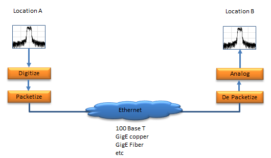
Radio over Ethernet. The RF spectrum is digitized and packetized at one end, and the same spectrum is rebuilt from the packets at the other end.
- At Location A, a spectrum plot shows the RF signal. It goes down through a Digitize block and a Packetize block.
- The packets cross a cloud labelled Ethernet. The note under the cloud lists 100 Base T, GigE copper, GigE Fiber and so on.
- At Location B, a De Packetize block and an Analog block rebuild the signal. The spectrum plot at the top has the same shape as the one at Location A.
The Digitize block sets the bit rate. It samples the signal as complex I and Q values, so the bit rate is the sample rate x 2 x the bits per sample. Take a 20 MHz LTE carrier. In 36.211 v19.3.0, a 10 ms radio frame is 307200 Ts long, so the basic sample rate is 30.72 Msps, which is 2048 x 15 kHz. With 15 bits for I and 15 bits for Q, one carrier on one antenna needs 30.72 x 2 x 15 = 921.6 Mbit/s before any packet header is added.
Signal | Sample rate | Bits for I + Q | Payload bit rate |
LTE 20 MHz, 1 antenna | 30.72 Msps | 2 x 15 | 921.6 Mbit/s |
LTE 20 MHz, 1 antenna | 30.72 Msps | 2 x 16 | 983.0 Mbit/s |
NR 100 MHz at 30 kHz SCS, 1 antenna | 122.88 Msps | 2 x 16 | 3.93 Gbit/s |
The 122.88 Msps in the last row is a typical choice, 4096 x 30 kHz, not a fixed value. Even so, the numbers show the problem. A 100 Base T link cannot carry even one LTE carrier in this form. GigE can carry about one, and a 100 MHz NR carrier needs a 10 Gbit/s link for each antenna. This is why real fronthaul links compress the samples, or move part of the physical layer into the radio unit so that less data crosses the link. IEEE 1914.3 defines how radio samples are put into Ethernet frames, and eCPRI is another widely used fronthaul format over Ethernet.
The RF signal crosses the link as I and Q samples : Digitize and Packetize at one end, De Packetize and Analog at the other.Bit rate is sample rate x 2 x bits per sample : a 20 MHz LTE carrier with 15 bit samples needs 921.6 Mbit/s for one antenna.Raw samples fill a link quickly : wide carriers and many antennas push fronthaul towards compression or a different functional split.
What would be the advantage of using this technology comparing to the conventional RF cable ?
You can easily think of a couple of obvious advantage. Most of them come from one fact. Once the signal is digital, the cable loss no longer degrades the signal, as long as the bits arrive without errors.
i) It would suffer from signal attenuation much less than RF cable, implying that it would need much less ampliflication and as result much less energy to transfer the signal.
ii) Cabling Cost would be much lower
iii) If you use Copper based ethernet, you may be able to remove even power supply cable for the end-unit by using PoE(Power over Ethernet)
These advantages come with three costs, and the design has to accept all of them. The first is bandwidth. As the table in the previous section shows, raw samples need a lot of it. The second is conversion quality. The Digitize block adds quantization noise and the Analog block adds its own distortion, so the rebuilt spectrum is never better than the converters. The third is timing. A packet network adds delay, and the delay varies from packet to packet. A radio needs a fixed delay and an accurate frequency, so the link also needs a timing method such as IEEE 1588 PTP or Synchronous Ethernet, and a buffer at the receiving end.
The quantization noise can be estimated. For an ideal converter with N bits and a full-scale sine wave, the signal to quantization noise ratio is 6.02 x N + 1.76 dB. So 15 bits give about 92 dB, which is far more than any radio signal needs. In practice fewer bits are enough, and this is one reason why sample compression works.
A digital link does not lose signal quality with distance : the signal survives the cable as long as the bits arrive without errors.The converters set the quality : an ideal N bit converter gives about 6.02 x N + 1.76 dB of signal to quantization noise ratio.Packet delay must be controlled : the radio needs fixed timing, so the link needs a timing protocol and a buffer.
Why carry analog RF over an Ethernet cable ?
Some systems keep the signal analog and use only the Ethernet cable itself. This avoids the bit rate problem of the previous sections completely, but it gives up the loss-free digital link.
In some application, they use Ethernet cable not as packet packet protocol but as simple copper cable. It may sound a little primitive comparing to the case described above, but there are a couple of advantage as well. It does not require AD/DA conversion and packetizing overhead (complexity). Also this can cover much more distance (up to a couple of hundred meters) comparing to the case described above( max 100 meters but much shorter distance in practice).
The diagram below keeps the two locations of the diagram in the previous section. The digital blocks and the Ethernet network are gone, and only an Analog block remains at each end.
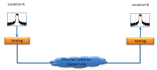
Analog RF over an Ethernet cable. The cable is only a copper line, so no digitizing or packetizing is needed.
- At Location A, the spectrum goes into an Analog block and directly onto the cable.
- The cloud in the middle is labelled Ethernet Cable as Copper Line. No network sits in the path.
- At Location B, another Analog block delivers the same spectrum.
The 100 m in the text above is the limit of a standard Ethernet link, which the packet solution has to respect. The analog solution does not run the Ethernet protocol, so that limit does not apply. But a twisted pair cable now carries the signal as an analog waveform. The cable loss rises with frequency, and noise picked up along the cable stays in the signal. So the Analog blocks usually do more than pass the signal through. Some systems shift the RF signal to a lower frequency where the cable loss is smaller, and the Analog blocks amplify and equalize it.
Analog transport removes the converters and the packet overhead : there is no sample rate and no bit rate to worry about.The Ethernet 100 m limit does not apply : the cable is used as a copper line, not as an Ethernet link.Cable loss and noise stay in the signal : the analog ends must amplify and equalize the signal, and some also shift its frequency.
Any advantage of using Copper wire over Optical fiber ?
In terms of technical aspect, I think Optical Fiber has more advantages over Copper in this application. So adopting Optical fiber is getting wider and wider, but still Copper ethernet cable would hold some advantage in practical sense.
- i) Cost of copper wiring would be lower than optical fiber
- ii) More importantly, we can use PoE (Power over Ethernet) and remove power line if we use copper ethernet cable. This will be huge advantage in terms of equipment deployment.
The technical advantages of fiber are easy to list. Fiber reaches kilometres instead of 100 m, and it carries 10 Gbit/s and more on one link. It is also immune to electromagnetic interference, because it carries light instead of current. For a macro base station, where the radio sits at the top of a tower and the baseband unit sits at the bottom, fiber is therefore the normal choice.
Copper is strongest where the distances are short and the radio units are many and small. An indoor small cell or a distributed antenna node in an office is one case. There, one cable that carries both the data and the power removes a separate electrical installation at every unit.
Fiber wins on distance, capacity and interference : it is the normal choice for macro site fronthaul.Copper wins on installation : PoE powers the remote unit over the same cable.