Whenever a signal travels from a source to a load, part of it may come back. The reflection coefficient is the number that says how much comes back and with what phase. VSWR, Return Loss and S11 are all built on it. So let's first see what the coefficient measures, then how the impedances set it, and finally how it turns into the other indicators.
- What does the reflection coefficient measure ?
- How do the impedances set the reflection coefficient ?
- How is the reflection coefficient related to VSWR and Return Loss ?
What does the reflection coefficient measure ?
A wave that meets a change in the medium does not simply continue. Part of it passes and part of it returns, and the reflection coefficient describes the returning part.
If a electric wave (or electro-magnetic wave) hits a discontinuous phase, there can be largely two possible paths. In one path, the signal goes through the discontinuity and in the other path it bounce back from the plane as illustrated below.
The sketch below draws an incident wave that arrives from the left at a vertical boundary. The arrows show the two directions the wave can take after the boundary.

A wave at a discontinuity. One part is transmitted through the boundary and the other part is reflected back towards the source.
- The green wave on the left travels to the right, as the green arrow above it shows. This is the incident wave.
- At the blue boundary, the red arrows split. One arrow continues through the boundary, and the other turns back.
- The lighter green wave on the right is the transmitted part. The blue wave below travels to the left, as the blue arrow shows, and it is the reflected part.
How much portions of the signal goes through the phase and how much portions get bounced back is dependent on various factors. Out of these two path, 'Reflection Coefficient' is an indicator showing how much portions of the impinging signal get bounced back and it is defined as shown below.
The diagram below puts the incident voltage and the reflected voltage on the same time axis. The marks at the right measure the amplitude of each wave.
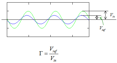
The reflection coefficient is the ratio of the reflected voltage to the incident voltage. A smaller reflected wave means a smaller coefficient.
- The green sine wave is the incident wave. Its amplitude is marked Vin.
- The blue sine wave is the reflected wave. Its amplitude is smaller and is marked Vref.
- The formula under the plot is Γ = Vref / Vin.
The plot shows the two waves nearly in phase, but that is only one case. In general Vref and Vin are phasors, so Γ is a complex number with a magnitude and a phase. The magnitude |Γ| is between 0 and 1 for any passive load. The phase tells whether the reflected wave returns in phase with the incident wave, in opposite phase, or somewhere in between.
Γ is a voltage ratio, and power goes with the square of voltage. So the fraction of the incident power that is reflected is |Γ|2, and the fraction that reaches the load is 1 - |Γ|2. For example, |Γ| = 0.2 means that 4 % of the power returns and 96 % is delivered.
Γ is a voltage ratio : Γ = Vref / Vin, and |Γ| lies between 0 and 1 for a passive load.Γ is complex : its phase tells how the reflected wave lines up with the incident wave.The reflected power is |Γ|2 : a voltage ratio of 0.2 returns only 4 % of the power.
How do the impedances set the reflection coefficient ?
In a circuit the discontinuity is a change of impedance. So the reflection coefficient can be written directly from the impedances on each side of that change, without measuring any waves.
In electric circuit, the reflection coefficient can be expressed as below.
The circuit below has a source with a source impedance ZS on the top line and a load ZL on the right. The arrow marked Γ points at the load terminals.
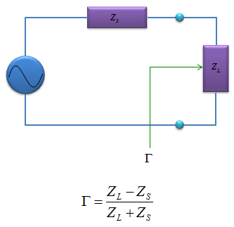
Reflection at the load. The coefficient depends only on how different ZL is from the impedance it is compared with.
- The sine wave symbol on the left is the source. ZS sits in series with it on the top wire.
- ZL is connected between the two dots on the right side.
- The formula under the circuit is Γ = (ZL - ZS) / (ZL + ZS).
The formula needs one note on what ZS stands for. On a transmission line, the load is compared with the characteristic impedance Z0 of the line, and the usual form is Γ = (ZL - Z0) / (ZL + Z0). In a 50 ohm system the source and the line are both 50 ohm, so the two forms give the same number. If the source impedance is complex, the formula that describes the power transfer uses its conjugate, Γ = (ZL - ZS*) / (ZL + ZS).
Three special cases are worth remembering. A matched load, ZL = Z0, gives Γ = 0 and no reflection. An open circuit gives Γ = +1, so the whole wave returns in phase. A short circuit gives Γ = -1, so the whole wave returns in opposite phase. The table below adds a few ordinary loads on a 50 ohm line.
ZL on 50 ohm | Γ | |Γ| | Reflected power |
50 ohm | 0 | 0 | 0 % |
75 ohm | +0.2 | 0.2 | 4.0 % |
100 ohm | +0.333 | 0.333 | 11.1 % |
25 ohm | -0.333 | 0.333 | 11.1 % |
50 + j50 ohm | 0.2 + j0.4 | 0.447 | 20.0 % |
Short, 0 ohm | -1 | 1 | 100 % |
Open | +1 | 1 | 100 % |
Note the 100 ohm and 25 ohm rows. Both loads are off by a factor of two, one above and one below 50 ohm, and both give the same |Γ| of 0.333. Only the sign differs. So the magnitude alone cannot tell whether a load is too high or too low. The phase of Γ, or a Smith chart, is needed for that.
The reflection coefficient compares two impedances : Γ = (ZL - Z0) / (ZL + Z0), and in a 50 ohm system Z0 = ZS = 50 ohm.Match, open and short are the reference points : they give Γ = 0, +1 and -1.A load too high and a load too low can give the same |Γ| : the sign or phase of Γ tells them apart.
How is the reflection coefficient related to VSWR and Return Loss ?
Instruments rarely display Γ itself. They display VSWR, Return Loss or S11 instead, and each one is a different view of |Γ|. Once you can convert between them, a specification in one form can be checked against a measurement in another.
Reflection Coefficient is an indicator which is a basis of other indicator such as VSWR, Return Loss.
The incident and reflected waves add along the line and form a standing wave. The ratio of its maximum to its minimum voltage is VSWR = (1 + |Γ|) / (1 - |Γ|). Return Loss expresses how far below the incident power the reflected power is, RL = -20 log10|Γ| dB. Mismatch loss is the power that does not reach the load, ML = -10 log10(1 - |Γ|2) dB. On a network analyzer, S11 is the reflection coefficient at port 1 when the other ports are terminated in the reference impedance.
|Γ| | Example load on 50 ohm | VSWR | Return Loss | Mismatch loss |
0.2 | 75 ohm | 1.5 | 13.98 dB | 0.18 dB |
0.333 | 100 ohm or 25 ohm | 2.0 | 9.54 dB | 0.51 dB |
0.447 | 50 + j50 ohm | 2.62 | 6.99 dB | 0.97 dB |
1 | Open or short | infinite | 0 dB | all power reflected |
The table shows why a VSWR of 1.5 is often accepted. It reflects only 4 % of the power and costs less than 0.2 dB. Even a VSWR of 2 loses only about 0.5 dB. The reflected power can still matter for other reasons, for example because it returns into a power amplifier. On a lossless line, |Γ| stays the same at every point and only its phase rotates. So the VSWR and the Return Loss measured through a lossless cable are the same as at the load, while the phase of Γ changes with the cable length.
VSWR, Return Loss and mismatch loss all come from |Γ| : VSWR = (1 + |Γ|)/(1 - |Γ|) and RL = -20 log10|Γ|.A moderate mismatch costs little power : VSWR 1.5 loses 0.18 dB and VSWR 2 loses 0.51 dB.A lossless cable rotates Γ but does not change |Γ| : the VSWR reading is the same at either end of the cable.