VSWR stands for Voltage Standing Wave Ratio. To understand this term completely, you need to know what is 'Standing Wave'. VSWR is one of the most common ways to state how well an antenna, a cable or an amplifier port is matched to its system impedance, usually 50 ohm. A perfect match gives a VSWR of 1, and any mismatch gives a larger number.
The sections below build the idea in four steps. First comes the standing wave itself, then the ratio that gives VSWR its name. After that, the reflection at a boundary produces the standing wave, and the last section converts VSWR into return loss and lost power.
- What is a Standing Wave ?
- What is the Standing Wave Ratio ?
- How is VSWR related to the Reflection Coefficient ?
- How much power does a given VSWR cost ?
What is a Standing Wave ?
You might have already learned about the standing wave in your high school physics class. Just refresh your mind, let me explain what the standing wave is.
Let's suppose that two waves with the same wavelength travels in opposite direction as shown below. One wave is represented as blue line and it is treveling in right direction. The other wave is represented as green line and it is treveling in left direction. As you learned in high school physics, these two waves would get summed up and the summed up wave is represented as red line.
This summed wave changes over time only in terms of amplitude but does not change in phase. Simply put, the location of nodes where the amplitude is zero never changes. Since the location of nodes does not change, the red wave looks as if it stays at the same position meaning 'it STANDs there'. This is why the red wave is called 'Standing Wave'.
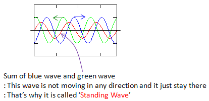
Two waves of the same wavelength travelling in opposite directions. Their sum is the red standing wave.
With only single snapshot as shown above, it would be difficult for you to understand the standing wave intuitively. To understand the standing wave visually and to confirm if the description above, you would need multiple snapshots showing a sequence of transisions of the two traveling waves over time. You can draw these sequence by hand, but that would be very tedius... just using a simple matlab code as shown below, you can create a long sequence of snapshots showing how standing wave is created.
The listing below draws 20 snapshots. The variable t is the position along the line, and the loop index i is the time step. At each step the green wave, sin(t + phase), moves to the left, and the blue wave, r x sin(t - phase), moves to the right. The value of r is the amplitude of the blue wave relative to the green wave. The listing shows r = 0.5, which produces Case 2 further down. Case 1 uses r = 1.
t = 0:pi/20:20*pi;
ph = pi/20;
r = 0.5;
for i=1:20
subplot(4,5,i);
plot(t,sin(t+(i-1)*ph),'g-',t,r*sin(t-(i-1)*ph),'b-',t,sin(t+(i-1)*ph)+r*sin(t-(i-1)*ph),'r-');
axis([0 6*pi -2 2]);
set(gca,'xticklabel',[]);set(gca,'yticklabel',[]);
title(['(' int2str(i) ')']);
end
One example sequence of snapshots of two traveling waves (blue one traveling right and green one traveling left. The red one is the wave formed by the summation of blue one and green one). First look at the red waves in all of the snapshots.
- Does the amplitude of the red wave changes in each of the snapshots ? --> Yes
- Does the frequency and wave length of the red wave changes in each of the snapshots ? =-> No
- Does the location of nodes (the place where the value gets zero) changes in each of the snapshots ? --> No
Let me give you some other questions to understand the characteristics of standing wave even further.
- What is the snapshot number showing the standing wave with largest amplitude ? --> It is (1). This is the snapshot where two traveling wave (blue and green) exactly overlap each other.
- What is the snapshot number showing the standing wave with smallest amplitude ? --> It is (11). This is the snapshot where two traveling wave (blue and green) alignes in such a way that the two waves has 180 degree phase difference.
< Case 1 >
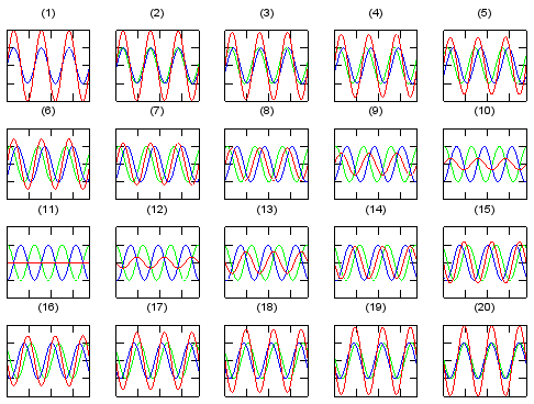
- In (1) the blue and green waves lie on top of each other, and the red sum has twice their amplitude.
- From (2) to (10) the two waves slide apart and the red wave shrinks. In (11) they are 180 degree apart, and the red wave is a flat line.
- From (12) to (20) the red wave grows again. Its zero crossings stay at the same positions in every snapshot.
A standing wave needs two waves travelling in opposite directions : with the same wavelength, their sum only grows and shrinks in place.Equal amplitudes give true nodes : the nodes stay at zero at every instant, so the pattern does not move along the line.
What is the Standing Wave Ratio ?
In a real line, the reflected wave is almost always smaller than the wave that goes forward. So the useful question is what happens when the two amplitudes differ. The answer gives the ratio that VSWR is named after, and it shows why the ratio tells you how large the reflection is.
In the example above, the amplitude of the two traveling wave are exactly same. What if the amplitude of the two traveling wave is different (wave length and frequency of the two waves are still same).
Let me give the same question as I asked you above.
- Does the amplitude of the red wave changes in each of the snapshots ? --> Yes
- Does the frequency and wave length of the red wave changes in each of the snapshots ? =-> No
- Does the location of nodes (the place where the value gets zero) changes in each of the snapshots ? --> Yes
The answer to the last question differs from Case 1, so let's check it with the formula. With r = 0.5, the red wave is sin(t + a) + 0.5 sin(t - a), where a is the phase step. At a = 0, snapshot (1), it is 1.5 sin(t), with zero crossings at multiples of π. At a = π/2, snapshot (11), it is 0.5 cos(t), with zero crossings shifted by π/2, a quarter wavelength. So the zero crossings move between snapshots. With unequal amplitudes the sum is a partial standing wave, a standing wave plus a travelling wave, and it has minimum points rather than true nodes.
Let me give you some other questions to understand the characteristics of standing wave even further.
- What is the snapshot number showing the standing wave with largest amplitude ? --> It is (1). This is the snapshot where two traveling wave (blue and green) has the same phase.
- What is the snapshot number showing the standing wave with smallest amplitude ? --> It is (11). This is the snapshot where two traveling wave (blue and green) alignes in such a way that the two waves has 180 degree phase difference. But unlike < Case 1>, the amplitude of the standing wave does not become zero in this case because the amplitude of the two traveling wave is different.
< Case 2 >
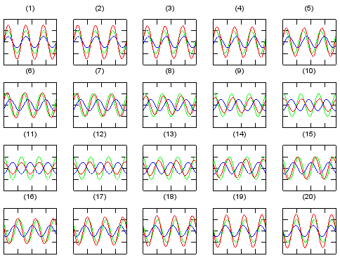
- The green wave has amplitude 1 and the blue wave has amplitude 0.5, as in the listing with r = 0.5.
- In (1) the red sum reaches 1.5. In (11) it drops to 0.5 but never to zero.
Now let's take the ratio of the standing wave amplitude for two snapshots with the smallest amplitude and the largest amplitude. In case of the two examples we saw above, it is the ratio of standing wave amplitude for snapshot (1) and (11). This ratio of standing wave with maximum amplitude and minimum amplitude is called 'Standing Wave Ratio'. Standing Wave Ratio for the first and second example that we saw above can be illustrated as below. (The upper one represents the min/max standing wave amplitude difference for < Case 1 > and the lower one represents the min/max standing wave amplitude difference for < Case 2 > )
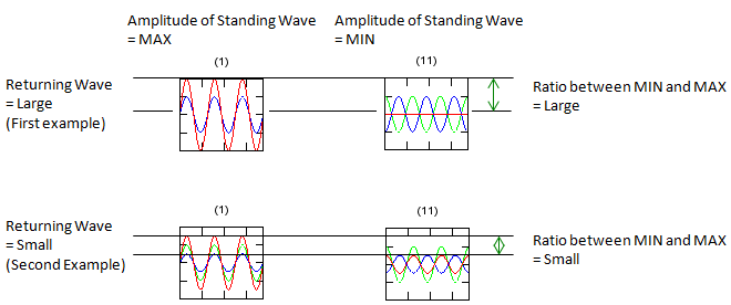
A large returning wave gives a large gap between the maximum and the minimum. A small returning wave gives a small gap.
- The left column is snapshot (1), labelled Amplitude of Standing Wave = MAX. The right column is snapshot (11), labelled Amplitude of Standing Wave = MIN.
- The upper row is labelled Returning Wave = Large (First example), and the ratio between MIN and MAX is large. The lower row is labelled Returning Wave = Small (Second Example), and the ratio is small.
If the two traveling wave represents the voltage of a signal, the Standing Wave Ratio is called 'Voltage Standing Wave Ratio (VSWR)'.
As you see in the two examples, you may notice the closer amplitude of the traveling wave are, the larger SWR. In other words, if you have larger SWR, the amplitude of the two traveling wave is similar. If you have smaller SWR, it means the amplitude of the traveling waves are much different (one is big and the other is very small).
We can put numbers on the two cases. With amplitudes 1 and r, the maximum of the red wave is 1 + r and the minimum is 1 - r. So the ratio is (1 + r) / (1 - r). For Case 2, with r = 0.5, this is 1.5 / 0.5 = 3. For Case 1, with r = 1, the minimum is 0 and the ratio is infinite. The same formula appears in the next section as the definition of VSWR, with r replaced by the reflection coefficient.
SWR is the maximum of the standing wave divided by its minimum : with amplitudes 1 and r, it is (1 + r) / (1 - r).A larger returning wave gives a larger SWR : equal amplitudes give an infinite SWR, and no returning wave gives an SWR of 1.Unequal amplitudes give a partial standing wave : its minimum is not zero, and its zero crossings move.
How is VSWR related to the Reflection Coefficient ?
A returning wave needs a cause, and on a transmission line the cause is a mismatch. This section shows where the reflected wave comes from, and then turns the SWR formula into the VSWR formula used on datasheets.
Where we see these standing wave most commonly ? The most common situation is the case where a traveling wave hits the boundary of another medium. In such a case, some portions of wave would transfer to the other medium but some portion of the wave would get reflected back as illustrated below.

This reflected wave would travel in opposite direction to the original wave but it's wave length (frequency) remain same as the original wave. As a result, the original wave and the reflected wave form a standing wave.
Based on how much portion of the original wave gets reflected from the boundary (this is described by Reflection Coefficient), you can calculate the VSWR using the following equations.
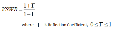
The reflection coefficient is in general a complex number, Γ = (ZL - Z0) / (ZL + Z0). The formula above uses its magnitude, so read Γ there as |Γ|, with 0 ≤ |Γ| ≤ 1. The magnitude alone sets VSWR, and the phase of Γ is lost. For example, on a 50 ohm line, a 100 ohm load gives Γ = +1/3 and a 25 ohm load gives Γ = -1/3. Both give VSWR = 2, so the VSWR cannot tell you whether the load is too high or too low.
What is the intuitive relationship between the reflection coefficient and VSWR ? You can guess from the following examples. In short, if you have larger reflection coefficient, you would get larger VSWR and if you have smaller reflection coefficient, you would get smaller VSWR
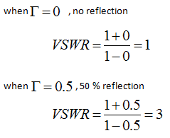
The label 50 % reflection for Γ = 0.5 refers to the voltage. Power goes with the square of the voltage, so Γ = 0.5 reflects 0.52 = 25 % of the power. The table in the last section lists both for common VSWR values.
Since reflection coefficient is tighly related to S11, you can represent VSWR using S11 as well, as shown below.
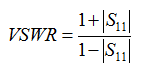
This form uses |S11|, the magnitude, for the same reason. A network analyzer measures S11 directly, so it can display VSWR, return loss or the Smith chart from the same measurement.
A mismatch between line and load creates the reflected wave : Γ = (ZL - Z0) / (ZL + Z0).VSWR = (1 + |Γ|) / (1 - |Γ|) : it runs from 1 for a perfect match to infinity for a full reflection.VSWR has no phase : a 100 ohm load and a 25 ohm load on a 50 ohm line both show VSWR 2.
How much power does a given VSWR cost ?
A VSWR number on a datasheet does not say directly how much power is lost. Engineers usually need that in dB, as return loss or as mismatch loss. The formulas below convert one into the other, and the table lists the values you will meet most often.
Start from |Γ| = (VSWR - 1) / (VSWR + 1). The return loss is RL = -20 log10|Γ| in dB, and a larger return loss means a better match. The reflected power is |Γ|2 of the incident power. The mismatch loss is the drop in delivered power, -10 log10(1 - |Γ|2) in dB.
VSWR |
|Γ| |
Return Loss, dB |
Reflected Power, % |
Mismatch Loss, dB |
1.0 |
0 |
infinite |
0 |
0 |
1.1 |
0.048 |
26.4 |
0.23 |
0.010 |
1.2 |
0.091 |
20.8 |
0.83 |
0.036 |
1.5 |
0.200 |
14.0 |
4.0 |
0.177 |
2.0 |
0.333 |
9.5 |
11.1 |
0.512 |
3.0 |
0.500 |
6.0 |
25.0 |
1.249 |
Read the last column with care. Even a VSWR of 2 loses only about 0.5 dB of delivered power. So a moderate mismatch rarely matters for the power budget. It matters more for what the reflected power does. A power amplifier can see its load change and become less linear, a filter can change its response, and the reflected wave adds ripple to the frequency response of a long cable.
Where you measure VSWR also changes the number. The reflected wave travels through any cable between the instrument and the load twice, once forward and once back. So a cable with a loss of L dB adds 2L dB to the measured return loss. Let's take an extreme case. An open end reflects everything, so its return loss is 0 dB. Behind a cable with 3 dB of loss, the instrument sees a return loss of 6 dB, which is a VSWR of 3.0. The load looks far better than it is. For that reason, antenna VSWR is best measured at the antenna port, or with the cable loss removed by calibration.
Return loss and VSWR carry the same information : VSWR 1.5 is 14.0 dB return loss, and VSWR 2 is 9.5 dB.Reflected power grows with |Γ|2 : VSWR 2 reflects 11.1 % of the power, and VSWR 3 reflects 25 %.Mismatch loss is small for moderate VSWR : it stays below 0.2 dB up to VSWR 1.5.Cable loss hides a bad load : the reflected wave passes the cable twice, so a 3 dB cable in front of an open end still measures VSWR 3.