As the name indicate, Waveguide is a special type of structure that can guide a wave from once place to another place. Depending on what kind of wave to be guided, there can be several different types of waveguide. If it guides RF/Microwave/mmWave, those wave guide is called 'RF/Microwave Waveguide'. If it guides optical wave, it is called Optical waveguide. If it guides sound wave, it is called 'Acoustic waveguide'.
- What does an RF Waveguide look like ?
- What determines the frequency of wave that can travel through a wave guide ?
- Why we use Waveguide ?
What does an RF Waveguide look like ?
The purpose of this page is to give you the introduction to RF/Microwave Waveguide. Followings are some examples of RF/Microwave waveguide. It is almost like a metalic pipe with rectangular or circular cross section of hollow space.
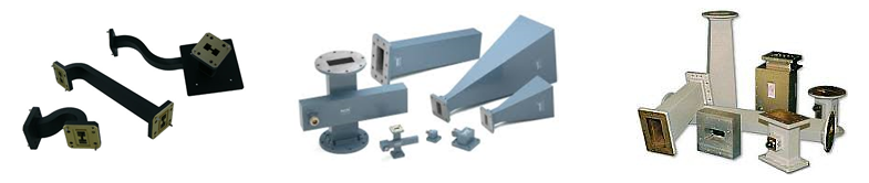
- On the left are rectangular waveguide sections with twists and bends. Each end carries a square flange with screw holes.
- In the middle are a tee junction, straight sections and horn antennas. A horn is a waveguide whose opening widens so that the wave leaves into free space.
- On the right are larger components with rectangular and circular flanges.
Even though you can design any shape of pipeline and cross-section shape of hollow space, there are several standardized shape at the opening at the ends of a waveguide to easily connect various kind of waveguide as shown below.
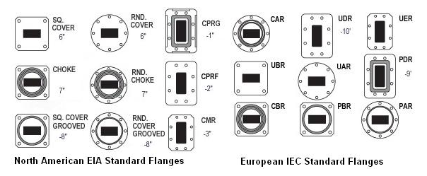
Note : This image is from http://mcli.com/documents/flanges.jpg
- The left group is labelled North American EIA Standard Flanges. It includes square and round cover flanges, choke flanges and grooved cover flanges, plus the CPRG, CPRF and CMR types.
- The right group is labelled European IEC Standard Flanges, with the CAR, UBR, CBR, UDR, UAR, PBR, UER, PDR and PAR types.
- A cover flange is flat. A choke flange has a groove around the opening, which makes a good RF contact without a perfect metal to metal joint. So a choke flange usually mates with a cover flange.
An RF waveguide is a hollow metal pipe : the wave travels in the air inside it, and the metal walls keep it there.Flanges are standardized : two waveguides connect only when their size and flange type match.
What determines the frequency of wave that can travel through a wave guide ?
As in most of the RF/Microwave/mmWave component (like Antenna, Coax cable), the frequency of a wave that can travel a wave guide is mainly determined by the dimension of the hollow space of the waveguide. As in Antenna, Coax Cable, the higher frequency it goes, the dimension of the hollow space (the cross section of the space) gets smaller.
A waveguide is a high pass structure. Below a cutoff frequency the wave does not travel at all; it decays within a short distance. Let's see where that cutoff comes from and how large it is for real waveguides.
In a rectangular waveguide with inner width a and height b, the lowest mode is TE10. Its cutoff frequency is fc = c / (2a) for an air filled guide. In other words, the wide wall must be at least half a wavelength across. The next modes are TE20, with cutoff c / a, and TE01, with cutoff c / (2b). A waveguide is normally used between the TE10 cutoff and the next cutoff, so that only one mode travels. Most rectangular waveguides use b close to a / 2, so the next cutoff is about twice the first one.
The WR name gives the inner width in hundredths of an inch. For example, WR-90 is 0.900 inch, or 22.86 mm, wide. The table below lists the cutoff frequencies computed from the dimensions for three common sizes.
Waveguide |
a x b, mm |
TE10 cutoff, GHz |
Next mode cutoff, GHz |
WR-90 |
22.86 x 10.16 |
6.56 |
13.11, TE20 |
WR-28 |
7.11 x 3.56 |
21.08 |
42.15, TE20 and TE01 |
WR-15 |
3.76 x 1.88 |
39.88 |
79.7, TE01 and TE20 |
The practical operating band sits inside these limits with a margin at both ends. Near the TE10 cutoff the loss and the dispersion rise quickly, and near the next cutoff a second mode can start. The wavelength inside the guide is also longer than in free space: λg = λ0 / √(1 - (fc/f)2). For WR-90 at 10 GHz, λ0 is 30.0 mm and λg is 39.7 mm. Keep this in mind when you size a waveguide component such as a quarter wave stub, because it has to use λg.
Refer to Waveguide : Waveguide in practice on Wikepedia for specific waveguide type and cutoff frequency.
The wide wall sets the lowest frequency : the TE10 cutoff is c / (2a), so a must be at least half a free space wavelength.A waveguide covers less than one octave : the single mode band runs from c / (2a) to about c / a.The guide wavelength is longer than the free space wavelength : in WR-90 at 10 GHz it is 39.7 mm instead of 30.0 mm.
Why we use Waveguide ?
Main reason to use Waveguide is that it is hard to use the flexible/handy coaxial cable at very high frequency (e.g, mmWave). As the frequency goes to very high, the dimension of Coaxial cable should be very small (e.g, less than a milimeter) and just a little bit of bending of a cable would drastically influence on transfer of a wave.
In terms of dimmension, Waveguide can be relatively larger than Coax cable for the same cutoff frequency. Also Waveguide does not allow arbitrary bending, so it can remove the problem caused by arbitrary bending of wave traveling path. (In some sense, this inflexibility can be a disadvantage of the waveguide, but in some sense it can be an advantage).
There is another important reason to use waveguide even in lower frequency application. Waveguide can handle much higher power (practically handling almost infinite power depending on how you design it) comparing to Coaxial cable. Due to this, you would see Waveguide is used even in such a low frequency that can be handled by Coax cable.
Two physical facts are behind these reasons. A waveguide has no center conductor and no dielectric filling. So there is no thin inner conductor to heat up and no dielectric to absorb power. The loss comes only from the currents in the walls, and those walls are large. So a waveguide usually has less loss than a coax cable at the same frequency. The power limit is still finite. It is set by voltage breakdown of the air inside, and a mismatch that raises the peak field lowers it.
The price is size and bandwidth. A waveguide must be at least half a wavelength wide, so at 2 GHz a WR-430 guide is already 109 mm wide. It also covers less than one octave, while a coax cable works from DC up to its own mode limit. This is why coax dominates at lower frequencies and inside equipment, and waveguide appears in radar, satellite ground stations, high power transmitters and mmWave test setups.
Waveguide has low loss : there is no dielectric and no thin center conductor, only the currents in large metal walls.Waveguide handles high power : the limit is the breakdown of the air inside, which is far above what a similar coax can take.Waveguide is large and narrow band : its width scales with the wavelength, and one size covers less than an octave.