Mixer can be called as a 'Frequency converter' or 'Frequency Translater'. It converts the frequency of an input signal to another frequency. In a receiver it moves the RF signal down to an IF or to baseband. In a transmitter it moves the signal up to the RF carrier frequency.
Every superheterodyne receiver and every up-converting transmitter has at least one mixer. The mixer moves a signal between the RF frequency on the antenna side and the IF or baseband frequency where filtering and processing are easier. This page starts with the principle and the math behind it, then looks at how a real mixer differs from the ideal one.
- How does a mixer change the frequency ?
- What does the math say ?
- Ideal vs Real Mixer
- What is Conversion Loss ?
How does a mixer change the frequency ?
A mixer has no knob for frequency. It changes the frequency by multiplying two signals, and the new frequencies come out of that product. Let's look at the block first and put the numbers in afterwards.
The principle of the mixer is very simple as shown below.
As you see, it has two input ports and two signals (in most case with different frequencies) comes in and produce one output signal which is generated by multiplying the two input signals. It means a mixer is just a component which multiplies two input signal. If you multiply two signals with different frequency, it produce a composite signal with the two frequencies, one of them is the sum of the two input frequencies and the other is the differences of the two frequencies. It is law of physics. (I don't know about your case. In our curriculum, I recal we learned this principle in high school physics class).
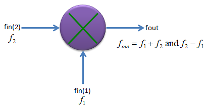
Generic mixer. Two inputs go in, and the output holds their sum and difference frequencies.
- The input fin(2) at f2 enters from the left, and the input fin(1) at f1 enters from the bottom.
- The output fout on the right is labelled fout = f1 + f2 and f2 - f1.
In most real application, one of the input port of a mixer is for RF input and the other port is for Local osciallator as shown below. As the result of the multiplication (mixing), you would get a frequencies, the frequency of which is lower than both inputs. Actually you will get two frequencies of the output, one is lower frequency than the two input (determined by the difference of the two input frequency) and the other one is higher frequency than the two inputs (determined by the sum of the two input frequency), but in most case we use the lower frequency part and filter out (remove) the higher frequency product.
With this principle and by changing the frequency of LO, you can change the input RF frequencies to any frequencies you want (at least in theory) and this is the main function of a mixer.
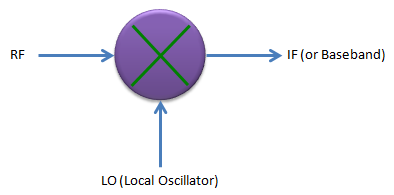
Mixer in a receiver. The RF and LO inputs produce an IF or baseband output.
One consequence of the difference frequency needs attention. The IF is |fRF - fLO|, so two RF frequencies give the same IF: one above the LO and one below it. The unwanted one is called the image frequency. For example, take fRF = 2140 MHz and fLO = 1950 MHz. The IF is 190 MHz. A signal at 1950 - 190 = 1760 MHz also produces a 190 MHz IF. The mixer cannot tell the two apart, so a filter before the mixer has to remove the image frequency.
A mixer multiplies two signals : the output holds the sum and the difference of the two input frequencies.The LO sets the conversion : changing the LO frequency moves the RF signal to the chosen IF.Two RF frequencies map to one IF : with a 1950 MHz LO, both 2140 MHz and 1760 MHz give a 190 MHz IF, so the image frequency must be filtered before the mixer.
What does the math say ?
The sum and difference frequencies are not a special property of the mixer. They come from one trigonometric identity, and the time and frequency plots below show that identity at work.
Now let's think about the principle of mixer in mathematical perspective. Don't get panic, this is just a high school math -:). As I described above, what mixer is doing is just to multiply two signals. If we assume that we have two signals expressed as a cos(2 pi f1 t) and b cos(2 pi f2 t). The multiplication of these two sinosodial function produces another sinosodial function which has two frequency component as shown below.
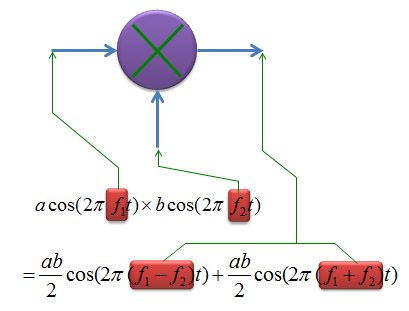
The product of two cosines is the sum of two cosines, one at f1 - f2 and one at f1 + f2.
The identity behind the picture is cos A x cos B = 1/2 [cos(A - B) + cos(A + B)]. So each output component has the amplitude ab/2. For example, with a = 2 and b = 3 each output cosine has the amplitude 3. The input frequencies f1 and f2 themselves do not appear in the output of an ideal multiplier.
If you plot the inputs and outputs of a mixer in both time and frequency domain, you would get following graphs.
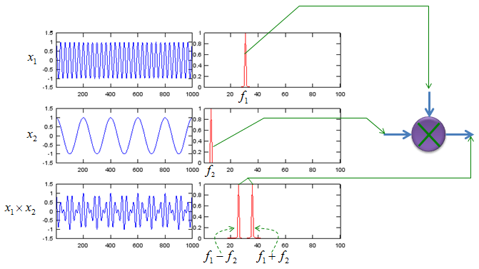
Mixer inputs and output in time and frequency. The product has no component at f1, only at f1 - f2 and f1 + f2.
- The top row, x1, is a fast sine wave with one spectral line at f1.
- The middle row, x2, is a slow sine wave with one spectral line at f2, near the left edge of the frequency axis.
- The bottom row, x1 x x2, is the fast wave with an envelope that follows x2. Its spectrum has two lines, marked f1 - f2 and f1 + f2, on either side of the empty position of f1.
A real mixer is usually not a perfect multiplier. Most diode and transistor mixers act closer to a switch that the LO turns on and off. A switching waveform contains the odd harmonics of the LO. So a real mixer also produces outputs at 3 fLO +/- fRF, 5 fLO +/- fRF and so on, and the IF filter has to remove them as well.
The product of two cosines is two cosines : one at the difference frequency and one at the sum frequency, each with the amplitude ab/2.An ideal multiplier removes the input frequencies : the spectrum of x1 x x2 has nothing at f1 or f2.A switching mixer adds LO harmonics : products such as 3 fLO +/- fRF also appear at the output.
Ideal vs Real Mixer
Like any other components, for Mixer as well, there would be some gaps between ideal behavior and real device. If you are mixer developer/designer, your job is to improve the behavior as close as the ideal behavior and if you are just user of the component, you job is to find out the device which fits the best fit your requirement.
I will put some plots later showing the deferences between the ideal mixer and real mixer. I was trying to find measurement result of very poor mixer but I didn't get it. There would a lot of ugly devices but hard to find the detailed measurement result for those ugly device -:)
Now let's think of what kind of factors are involved in producing non ideal behavior of a mixer. Most common factors are shown below and these are the factors that all of designer and users wants to get rid of. The factors shown here are produced by those signal component which directly reaches the other ports without going through operation process of the mixer.
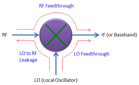
Leakage paths of a real mixer. Each red path carries a signal around the mixing process instead of through it.
RF feedthrough : This is generated by the component of RF input signal reaching directly to IF (output) port without going through mixer's operation block.
LO feedthrough : This is generated by the component of LO signal reaching directly to IF (output) port without going through mixer's operation block.
LO to RF leakage : This is generated by the comonent of LO signal reaching to RF input port without going through mixer's operation block.
Of course, the less you have this kind of factors, the better mixer you have.
A datasheet states these paths as isolation in dB, for example LO to IF isolation and LO to RF isolation. The LO is usually the strongest signal at the mixer, so its leakage matters most. For example, an LO drive of +7 dBm and an LO to IF isolation of 30 dB leave -23 dBm of LO at the IF port. LO to RF leakage travels backwards towards the antenna. In a direct conversion receiver, where the LO equals the RF carrier, the leaked LO also mixes with itself and appears as a DC offset at baseband.
Feedthrough bypasses the mixing : RF and LO signals reach the IF port without being converted.Isolation is the number to read : the leaked level is the drive level minus the isolation, so +7 dBm of LO and 30 dB of isolation give -23 dBm.LO to RF leakage goes backwards : it can reach the antenna, and in a direct conversion receiver it creates a DC offset.
What is Conversion Loss ?
The leakage paths above add unwanted signals. Conversion loss is the other side of a real mixer: the wanted IF signal comes out weaker than the RF signal went in. It is the first gain figure to check when a mixer sits in a receiver chain.
There is another aspects of real mixer which is different from ideal case. That is about output power. As shown in the mathematical model of the mixer at the top, in ideal case the amplitude of each output component of mixer is ab/2, but in reality the output power is smaller than the theoretical value. If you look at the power of RF input, the output power (IF power) tend to be lower than the RF input power. The difference between the RF input power and IF output power of a mixer is called 'Conversion Loss'.
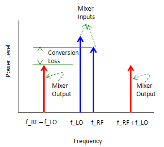
Conversion loss is the level difference between the RF input and the IF output.
- The blue arrows are the mixer inputs, at f_LO and f_RF. The LO arrow is the taller one.
- The red arrows are the mixer outputs, at f_RF - f_LO and f_RF + f_LO.
- The green bracket measures the conversion loss from the level of f_RF down to the level of the f_RF - f_LO output.
In dB the definition is a subtraction: conversion loss = PRF - PIF. For example, an RF input of -10 dBm and an IF output of -17 dBm give a conversion loss of 7 dB. Part of that loss is built into the mixing itself. The picture shows two outputs, and only one of them is used. The LO harmonics of a switching mixer take a further part of the power. For an ideal switching mixer, the amplitude of each output is 2/π of the RF amplitude, which is a loss of 3.9 dB. Diode and transistor losses come on top of that.
What would cause the conversion loss of the mixer ? It is mainly because a mixer also has non linear operating region as we saw in Amplifier. Conversion Loss gets larger as the RF input power to the mixer goes deeper into non linear operating region.
So two effects add up. At low RF input, the conversion loss is roughly constant and set by the design of the mixer, as described above. The non linear region adds extra loss once the RF input grows too large. The picture below shows that second effect.
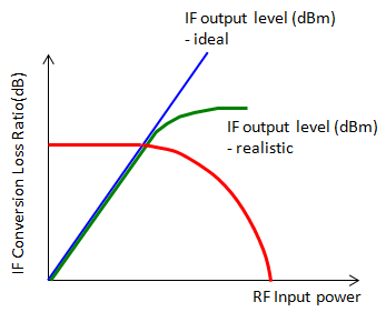
IF output against RF input. The realistic output compresses, so the conversion loss grows at high input power.
- The blue line is the ideal IF output level in dBm. It rises in proportion to the RF input power.
- The green curve is the realistic IF output level. It follows the blue line at low input and then flattens.
- The red curve, read on the IF Conversion Loss Ratio axis, is flat at low input and falls as the green curve compresses. A falling IF to RF ratio means a growing conversion loss.
Conversion loss is PRF - PIF in dB : -10 dBm in and -17 dBm out is 7 dB.Some loss is unavoidable : an ideal switching mixer already loses 3.9 dB, because the power splits into the sum, the difference and the harmonic outputs.Compression adds more loss : above the linear range the IF output flattens, so the conversion loss grows with the RF input.