Going into very details, 802.11 Physical Frame structure gets different from each standard(e.g, b/g/a/ac etc) and it is difficult to draw a single diagram to represent the physical frame structure of every WLAN standards. However, taking a very high level view, the physical frame structure of WLAN can be represented as follows.
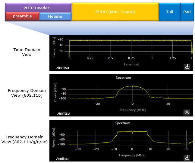
There are many different ways to represents PHY frames. Most common way would be to draw various diagram as you can easily find from specification documents or web search. I will use various diagrams as well, but I would try to put various captures from measurement equipment trying to give you more intuitive and realistic image.
The diagram above shows one frame in three views. At the top, the PLCP Header, made of the preamble and the header, comes first. The PSDU follows it, and the PSDU is the MAC frame. Tail and Pad close the frame. The time domain view below shows one frame of about 1.5 ms at a constant power level. The two spectrum views show why the frequency domain structure matters. The 802.11b DSSS signal has a rounded shape, while the OFDM signal of 802.11a/g/n/ac has a flat top with steep edges and a small notch at the center.
- Frequency Domain Structure
- Time Domain Structure/PHY Frame Structure
- 802.11a
- 802.11n
- 802.11ac VHT
- 802.11ad ControlPHY Frame
- 802.11ad Single Carrier PHY Frame
- 802.11ad Low Power Single Carrier PHY Frame
- 802.11ad OFDM PHY Frame
- Spectrum Analysis Example
- Reference :
Frequency Domain Structure
WLAN is using roughly two types of modulation method, DSSS and OFDM. DSSS is a kind of old technology which is the base technology for 802.11b and most of recent standard like 802.11a, g, n, ac are all based on OFDM. Following is summary of requency domain structure for OFDM based WLAN standard.
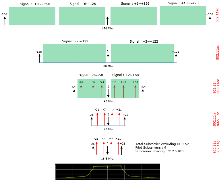
Each row of the diagram above is one channel bandwidth. The numbers on the axis are subcarrier indices, and the standards that use the row are printed in red on the right. The index 0 in the middle is the DC subcarrier, and it carries nothing. The arrows in the narrow channels mark pilot subcarriers, and the green blocks in the wide channels mark the ranges that carry data and pilots. The spectrum capture at the bottom shows the same structure on a real 20 MHz signal. It has a flat top, steep edges, and a small notch at DC.
- 802.11a/g, 20 MHz : 52 subcarriers from -26 to +26, not counting DC. Four of them, at -21, -7, +7 and +21, are pilots, so 48 carry data. The spacing is 312.5 kHz, which is 20 MHz divided by a 64-point FFT. The occupied width is 53 x 312.5 kHz = 16.56 MHz, and the diagram rounds it to 16.6 MHz.
- 802.11n/ac, 20 MHz : 56 subcarriers from -28 to +28. The pilots stay at -21, -7, +7 and +21, so 52 subcarriers carry data.
- 802.11n/ac, 40 MHz : subcarriers -58 to -2 and +2 to +58, which is 114 in total, on a 128-point FFT. Six pilots at +/-11, +/-25 and +/-53 leave 108 data subcarriers.
- 802.11ac, 80 MHz : subcarriers -122 to -2 and +2 to +122, which is 242 in total, on a 256-point FFT. Eight of them are pilots, so 234 carry data.
- 802.11ac, 160 MHz : four blocks, -250 to -130, -126 to -6, +6 to +126 and +130 to +250. This is two 80 MHz segments side by side, with 484 subcarriers, 16 pilots and 468 data subcarriers.
Let's turn these counts into a data rate, because that is where they matter. One OFDM symbol lasts 3.2 us, and the normal guard interval adds 0.8 us, so a symbol takes 4.0 us. The rate is the number of data subcarriers x bits per subcarrier x coding rate, divided by the symbol time. For 802.11a at 64-QAM with rate 3/4, this gives 48 x 6 x 3/4 / 4.0 us = 54 Mbps, the top rate of 802.11a/g. For 802.11n MCS 7 at 20 MHz, it gives 52 x 6 x 5/6 / 4.0 us = 65 Mbps. With the 0.4 us short guard interval, the symbol takes 3.6 us and the same MCS gives 72.2 Mbps. For one 802.11ac stream at 80 MHz, MCS 9 with 256-QAM rate 5/6 and short guard interval gives 234 x 8 x 5/6 / 3.6 us = 433.3 Mbps.
The subcarrier spacing stays at 312.5 kHz : from 802.11a to 802.11ac, a wider channel adds subcarriers and a larger FFT, and the spacing does not change.A wider channel gives more than a proportional number of data subcarriers : 40 MHz carries 108 data subcarriers, which is more than twice the 52 of 20 MHz, because the guard band and DC are shared.The data rate follows directly from the subcarrier count : data subcarriers x bits x coding rate / symbol time gives 54 Mbps for 802.11a and 433.3 Mbps for one 802.11ac stream at 80 MHz.
Time Domain Structure/PHY Frame Structure
The time domain structure or Physical Layer (PHY) frame structure of WiFi, as defined by the IEEE 802.11 standards, encompasses the organization of data, control information, and management information as they are transmitted over the air. This structure is crucial for ensuring reliable communication between WiFi devices.
The PHY frame structure can vary slightly depending on the specific version of the 802.11 standard being used (e.g., 802.11a, 802.11b, 802.11g, 802.11n, 802.11ac, etc.), as each version may introduce different modulation schemes, data rates, and channel bandwidths. However, the basic concept of a preamble, header, and payload remains consistent across these variations.
The design of the PHY frame structure is critical for the efficient use of the wireless medium, supporting various service qualities, and enabling coexistence with other signals in the same frequency band. It allows for dynamic adjustments in response to changes in signal strength, interference levels, and other factors affecting wireless communication.
Overall structure of WiFi PHY frame is made up of :
Preamble and Header: At the beginning of each WiFi frame, there is a preamble and header. The preamble is used for synchronization, allowing the receiver to establish the timing of the incoming signals. It also aids in signal detection and equalization. The header contains important control information, such as the rate at which the data is transmitted and the length of the payload.Payload: Following the header, the payload carries the actual data being transmitted. Majority part of the PHY payload is a MAC frame that can include user data, network management information, or control messages. The size of the payload varies depending on the type of frame and the specific requirements of the data being sent.
802.11a
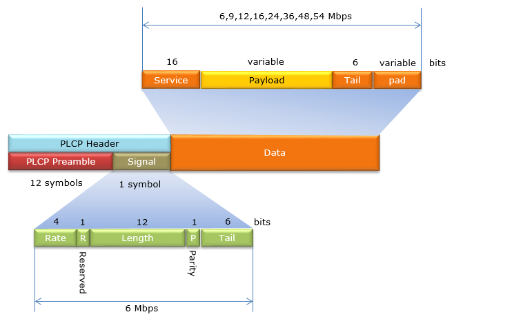
This is a diagram of the PHY frame structure for the 802.11a standard. 802.11a is the first OFDM PHY in the 802.11 family, and 802.11g uses the same frame in the 2.4 GHz band. The later formats keep this frame as their legacy part, so these fields appear again in 802.11n and 802.11ac.
This is breakdown of this frame :
PLCP Header: This is located at the beginning of PHY frame and it is made up of two parts - PLCP Preamble and Signal.PLCP Preamble: This is the Physical Layer Convergence Protocol preamble. It's used for synchronization and consists of 12 symbols that help the receiver to lock onto the signal and understand the modulation and coding schemes being used.Signal: It's a part of the PLCP header and it carries the information as follows- Rate (4 bits): Indicates the data rate at which the packet is transmitted.
- Reserved (1 bit): A reserved bit for future use or to maintain compatibility.
- Length (12 bits): Specifies the length of the PSDU (PLCP Service Data Unit), which is the actual data payload.
- Parity (1 bit): A bit to check the correctness of the header.
- Tail (6 bits): These are extra bits used to flush the convolutional decoder within the receiver.
Data: This is the actual payload that carries the user data. It's divided into:- Service (16 bits): Used for various service functions within the PHY layer.
- Payload: This is the variable-length field that carries the MAC frame
- Tail (6 bits): Similar to the tail bits in the PLCP header, these are used to clear out the decoder.
- Pad: Padding bits are used to ensure that the data payload is an integer number of symbols. The length of the pad varies depending on the size of the payload.
The Rate field selects one of eight data rates: 6, 9, 12, 18, 24, 36, 48 and 54 Mbps. The diagram above prints the fourth value as 16, but the 802.11a rate set has no 16 Mbps, and the value is 18 Mbps. The Signal field itself is always sent at 6 Mbps, with BPSK and rate 1/2 coding, so a receiver can read it before it knows the data rate. One symbol at that rate holds exactly 48 x 1 x 1/2 = 24 bits. That is the 4 + 1 + 12 + 1 + 6 bits of the Signal field. The Length field counts octets, so its 12 bits allow a PSDU of up to 4095 octets.
802.11n
This is overall structure of 802.11n PHY frame( also known as High Throughput (HT) Wi-Fi). It significantly improved data throughput and range over previous Wi-Fi standards through the use of multiple antennas, wider RF bandwidth, and more advanced signal processing. The 802.11n PHY frame structure supports enhanced modulation and coding schemes, allows for multiple spatial streams, and can utilize wider channel bandwidths, all of which contribute to the increased throughput and range of this standard compared to its predecessors.
The IEEE 802.11n standard introduced several enhancements over previous Wi-Fi standards, particularly with the PHY layer, to increase throughput. A notable feature of 802.11n is its ability to operate in different PHY modes to accommodate both older and newer devices: Legacy, Mixed, and Greenfield modes. These modes dictate how the PHY header is structured to either allow backward compatibility or to provide optimized performance.
Each of these modes has a specific use case:
Legacy Mode: Ensures that new 802.11n devices can communicate with older devices but doesn't take advantage of 802.11n's speed enhancements.Mixed Mode: Provides compatibility with older devices while allowing 802.11n devices to benefit from some of the standard's enhancements. If there are legacy devices in the area, the network typically operates in Mixed Mode to prevent interference and ensure all devices can understand the transmissions.Greenfield Mode: Optimizes performance for 802.11n devices, excluding older devices from the network. When an 802.11n device is communicating in Greenfield mode, it sends out a preamble that is only understandable by other 802.11n devices. This preamble signals that the following transmission will be using 802.11n-only features like MIMO or channel bonding, which are not compatible with older standards.
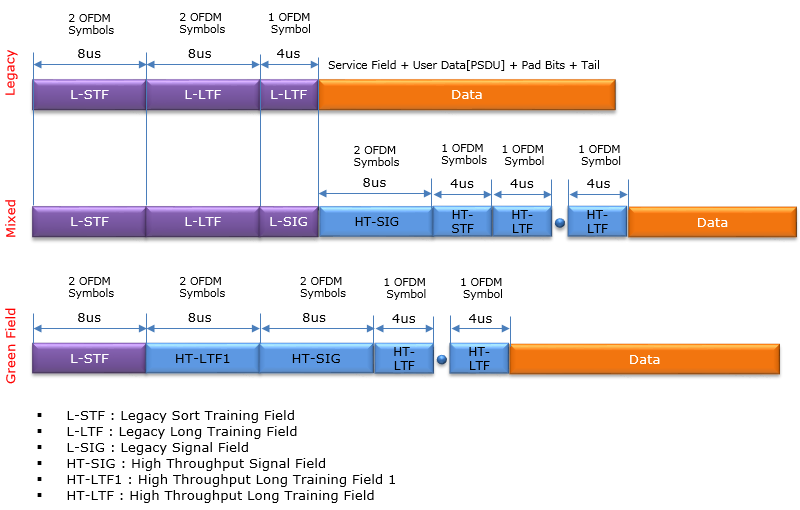
In the diagram above, the three formats share the same timing grid. The Legacy row labels its third field L-LTF, but that field is the L-SIG, one 4 us symbol, as the Mixed row shows. The Greenfield row replaces L-LTF with HT-LTF1 and has no L-SIG, so its HT-SIG starts 4 us earlier than in the Mixed row.
Following is the structure of the mixed mode frame.
The Mixed Mode Frame Structure in IEEE 802.11n is designed to ensure compatibility with legacy devices operating under older 802.11 standards such as 802.11a/b/g while providing the benefits of the n standard's enhancements. It allows 802.11n-compliant devices to communicate at high throughput rates without excluding legacy devices from the network.
The Mixed Mode frame structure is a combination of fields understandable by both legacy and HT (High Throughput) devices. It begins with a preamble that is compatible with legacy devices, followed by HT-specific fields that are ignored by legacy devices. After the preamble, there is an HT frame that includes the HT Signal field (HT-SIG), HT Short Training Field (HT-STF), and HT Long Training Fields (HT-LTFs). Finally, the frame carries the actual data payload.
The Mixed Mode frame structure thus supports communication in environments where both legacy and HT devices are present, ensuring that 802.11n devices can take advantage of higher data rates and more robust signal processing while maintaining backward compatibility with older Wi-Fi technologies.
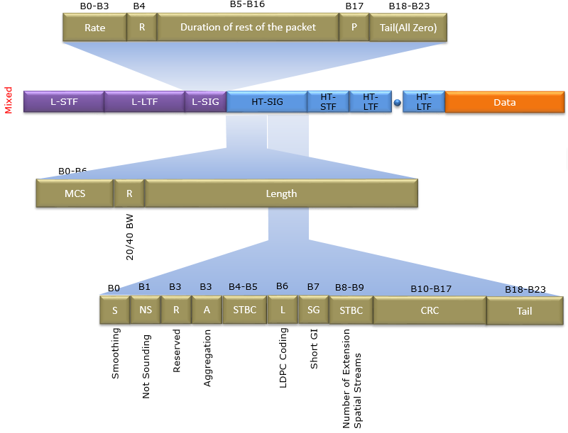
Followings are breakdown of the frame structure
L-STF (Legacy Short Training Field): An 8-microsecond field used for signal detection, AGC (Automatic Gain Control), and setting the radio frequency timing for legacy devices.L-LTF (Legacy Long Training Field): Another 8-microsecond field for fine-tuning frequency offset and channel estimation for legacy devices.L-SIG (Legacy Signal Field): A 4-microsecond field containing rate and length information readable by legacy devices, ensuring they can process the frame correctly up to this point.HT-SIG (High Throughput Signal Field): A two-symbol field specifically for 802.11n devices, carrying information required for decoding the HT data, such as MCS index, channel bandwidth, and guard interval.HT-STF (High Throughput Short Training Field): This is used to adjust the AGC again for the MIMO part of the frame in an 802.11n environment and lasts for 4 microseconds.HT-LTF (High Throughput Long Training Field): Used for fine channel estimation, MIMO channel calibration, and sounding. The number of HT-LTFs sent depends on the number of spatial streams being used.Data: Contains the MAC Service Data Unit (MSDU) or Aggregate MAC Service Data Unit (A-MSDU), along with any necessary padding bits and tail bits for proper decoding.
The top of the diagram above opens the L-SIG field of a mixed mode frame. Its Rate, Reserved, Parity and Tail bits are the same as in 802.11a. But the 12 bits in B5-B16 are labelled "Duration of rest of the packet" rather than Length. A legacy device reads this value, works out how long the transmission lasts, and stays off the medium until it ends. This is how a mixed mode frame protects itself from legacy devices that cannot decode HT-SIG. HT-SIG is sent with BPSK rotated by 90 degrees, called QBPSK, and an 802.11n receiver uses this rotation to tell an HT frame from a legacy frame.
Following is the PHY frame structure for a Greenfield format in the IEEE 802.11n standard. The Greenfield format is designed for an environment where only 802.11n devices are present and therefore does not need the legacy preamble and header. Greenfield mode can enhance efficiency because it skips the legacy preamble and header, reducing overhead and allowing for a shorter transmission time, which can improve network throughput under the right conditions.
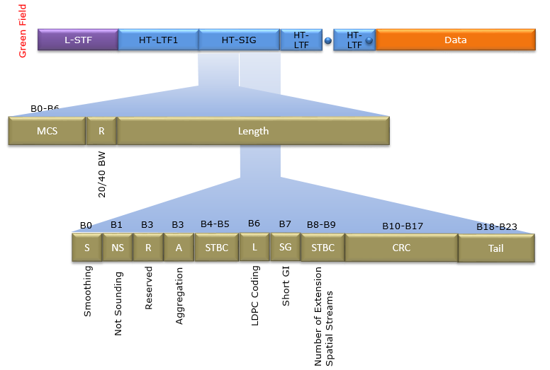
Here's a breakdown of the Greenfield frame structure:
L-STF (Legacy Short Training Field): The diagram labels this field L-STF. In the Greenfield format it is the HT-GF-STF, an 8 us short training field for signal detection and AGC. A legacy device cannot decode a Greenfield frame, so this field does not give backwards compatibility.HT-LTF1 (High Throughput Long Training Field 1): The first long training field specific to 802.11n, which is used for channel estimation. It's critical for MIMO operations and allows for fine-tuning the signal processing based on the current channel conditions.HT-SIG (High Throughput Signal Field): A field specific to 802.11n that provides detailed information about the transmission, such as the Modulation and Coding Scheme (MCS), data rate, and length of the frame.HT-LTFs (High Throughput Long Training Fields): Additional training fields are included based on the number of spatial streams being used. In a full MIMO configuration (e.g., 4 spatial streams), you would have one HT-LTF for each spatial stream.The first part of HT-SIG field includes:- MCS (Modulation and Coding Scheme, B0-B6): This indicates the modulation and coding used for the data fields of the frame.
- Bandwidth (R, B7): Signifies whether a 20 MHz or 40 MHz channel is used.
- Length (B8-B23): The length of the PSDU in octets.
The second part of HT-SIG are as follows:- B0: Smoothing required or not.
- B1: Not sounding PPDU.
- B2: Reserved.
- B3: Aggregation.
- B4-B5: STBC (Space-Time Block Coding) used or not.
- B6: Advanced coding (LDPC) used or not.
- B7: Short Guard Interval (SGI) used or not.
- B8-B9: Number of extension spatial streams.
- B10-B17: CRC over the HT-SIG bits.
- B18-B23: Tail bits.
Data: This is the main payload section, which carries the MAC frame including the MAC header, frame body, and Frame Check Sequence (FCS).
The HT-SIG bit numbers above follow the diagram, with one correction. The diagram labels both Reserved and Aggregation as B3, but the second part of HT-SIG counts B0, B1, B2 and B3 in order, so Reserved is B2. You can check the widths by adding them. The first part has 7 + 1 + 16 = 24 bits, and the second part has 1 + 1 + 1 + 1 + 2 + 1 + 1 + 2 + 8 + 6 = 24 bits. Each part fills one OFDM symbol of 24 bits at BPSK rate 1/2.
802.11ac VHT
Following is a representation of the PHY frame format and modulation specifics for the 802.11ac VHT (Very High Throughput). It shows the division of the signal into different fields, each with a specific function and duration in microseconds. The purpose of this structure is to allow devices to communicate the necessary information to decode and understand the subsequent data frames.
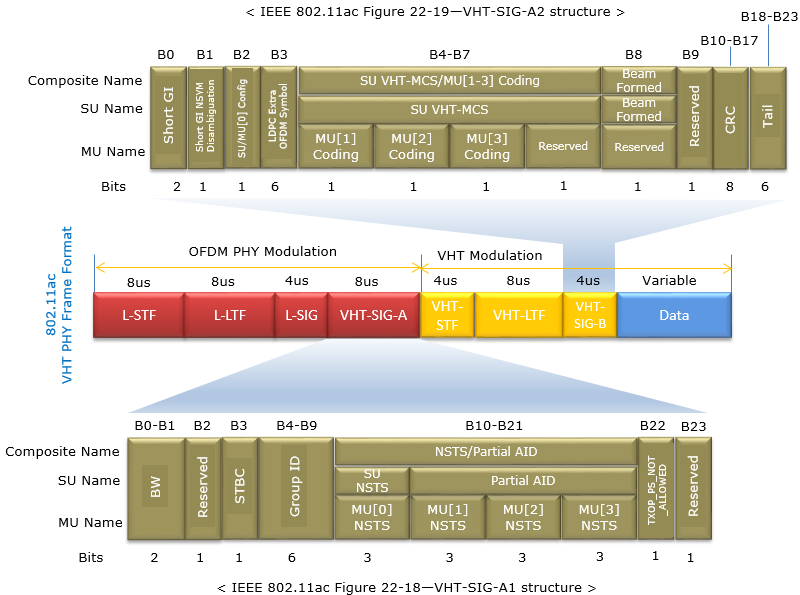
This frame is made up of two large segments :
OFDM PHY Modulation: This part of the diagram shows the preamble of the frame, which includes different fields such as L-STF (Legacy Short Training Field), L-LTF (Legacy Long Training Field), L-SIG (Legacy Signal), and VHT-SIG-A, each with a specified duration in microseconds. These are used for synchronization, channel estimation, and signaling for legacy devices.VHT Modulation: This part specifies fields that are specific to the 802.11ac standard, such as VHT-STF, VHT-LTF, and VHT-SIG-B, also with specified durations. These fields are used for channel estimation, signaling for 802.11ac devices, and other functions.
VHT-SIG-A takes two OFDM symbols in the OFDM PHY Modulation segment, and the two symbols carry VHT-SIG-A1 and VHT-SIG-A2 respectively
VHT-SIG-A1: - It's part of the frame preamble used for signaling in 802.11ac VHT (Very High Throughput) wireless communication.
- Contains information required by the receiver to decode the upcoming VHT frame.
- It's transmitted in a non-HT (High Throughput) format so that it can be decoded by devices not supporting VHT.
- Bandwidth (BW) field: Indicates the channel bandwidth (e.g., 20 MHz, 40 MHz, 80 MHz, etc.).
- STBC field: Indicates if Space-Time Block Coding is used for the transmission, which is a method to improve reliability.
- Group ID field: Used for group identification in multi-user MIMO environments.
- Number of Space-Time Streams (NSTS): Indicates the number of space-time streams used in the transmission.
- Partial AID field: A shortened association identifier that helps the receiver identify the transmission's intended recipient.
VHT-SIG-A2: - Also part of the preamble, it complements the A1 segment by providing additional information needed for frame decoding.
- Transmitted in the second VHT-SIG-A symbol, before VHT-STF, with its BPSK constellation rotated by 90 degrees (QBPSK). A VHT device uses this rotation to detect a VHT frame.
- Short GI (Guard Interval) field: Indicates whether a short guard interval is used, which can help increase data rate.
- Coding: Provides information on the coding used for the user’s data.
- MU-MIMO (Multi-User MIMO) Coding: Shows the coding for multi-user MIMO transmissions.
- Beamformed field: Indicates whether beamforming is used, which is a technique to direct signals towards specific receivers to improve signal quality.
- CRC (Cyclic Redundancy Check): A checksum for error-checking the VHT-SIG-A fields.
The bit positions in the diagram are the numbers to trust. VHT-SIG-A1 adds up to 2 + 1 + 1 + 6 + 12 + 1 + 1 = 24 bits. For VHT-SIG-A2, the Bits row in the diagram is shifted and adds up to 30, which cannot fit. The bit positions give B0 to B3 one bit each, B4-B7 four bits, B8 and B9 one bit each, the CRC in B10-B17 eight bits and the Tail in B18-B23 six bits, which is 24 bits. Note also the 8 us drawn for VHT-LTF. Each VHT-LTF symbol is 4 us, and the number of VHT-LTF symbols grows with the number of space-time streams, so the 8 us is one example.
802.11ad ControlPHY Frame
This is 802.11ad Control PHY Frame which carries control information which includes packet type, data length, and other parameters essential for the management and proper routing of the data packet through the network.
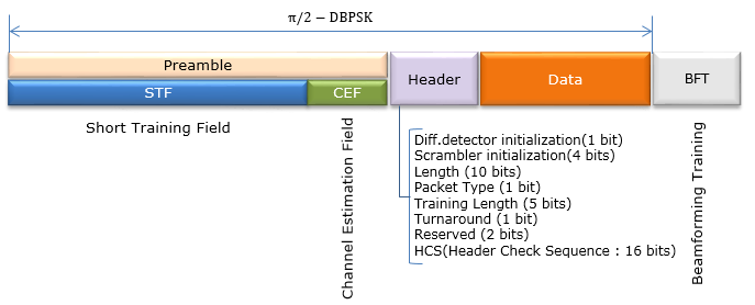
The composition of this frame is as follows :
Preamble: This part of the frame is used for synchronization and includes the Short Training Field (STF) and the Channel Estimation Field (CEF). It allows the receiver to lock onto the signal and begin interpreting it correctly.Header: Contains vital information for the receiver, such as modulation and coding schemes, frame length, and other control information.Data: The actual payload of the frame, which includes the transmitted information or user data.BFT: BeamForming Training. This is used for directional communication, which is a feature of 802.11ad that allows devices to increase signal quality and range.
The frame uses π/2 – DBPSK modulation, which is a type of phase modulation used for robust, low-complexity communication in wireless systems.
The detailed elements in the Header include:
Differential detector initialization (1 bit): Used for setting up the differential decoder at the start of the header decoding process.Scrambler initialization (4 bits): Provides the initial state for the scrambler, which is used to randomize the data and reduce the likelihood of long runs of zeroes or ones.Length (10 bits): Specifies the length of the data field.Packet Type (1 bit): Identifies the type of packet, which could be data or control.Training Length (5 bits): Indicates the length of the training field used for beamforming.Turnaround (1 bit): A bit indicating whether there is a switch from transmit to receive mode.Reserved (2 bits): Bits reserved for future use or for specific proprietary functions.HCS (Header Check Sequence - 16 bits): A checksum used for error detection in the header.
The Control PHY header adds up to 1 + 4 + 10 + 1 + 5 + 1 + 2 + 16 = 40 bits. The Length field has only 10 bits here, against 18 bits in the other 802.11ad headers below. The Control PHY carries short control frames at a low rate, so it does not need a longer field.
802.11ad Single Carrier PHY Frame
This is 802.11ad Single Carrier PHY Frame which carries control information which includes packet type, data length, and other parameters essential for the management and proper routing of the data packet through the network.
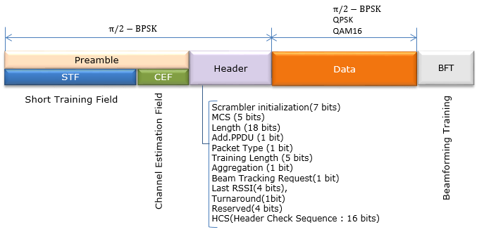
The detailed elements in the Header include:
Preamble: The preamble is used to prepare the receiving system for the incoming frame. It includes the Short Training Field (STF) for signal detection, timing, and coarse frequency correction, and the Channel Estimation Field (CEF) for fine frequency and channel estimation.Header: This section contains metadata about the frame, including the transmission rate, frame length, and other control information necessary for the receiver to correctly decode the incoming data.Data: This is the payload of the frame, containing the user data that is being transmitted.Beamforming Training (BFT): This segment is used for the beamforming process, which is critical for communication in the 60 GHz band. Beamforming optimizes the signal quality and strength by focusing the transmission in a specific direction between the transmitter and receiver.
The modulation techniques indicated (π/2 – BPSK, QPSK, QAM16) refer to the types of modulation used for different parts of the transmission, indicating the method by which data is encoded into radio waves.
In the header, the fields include:
Scrambler Initialization (7 bits): Sets up the pattern for scrambling the data to reduce interference.Modulation and Coding Scheme (MCS) (5 bits): Specifies the data rate and error correction methods.Length (18 bits): Indicates the length of the data field.Additional PPDU (1 bit) and Aggregation (1 bit): Indicate whether there are additional PPDU fields and whether multiple frames are aggregated together, respectively.Training Length (5 bits): Specifies the length of the training field for beamforming.Beam Tracking Request (1 bit): Indicates if beam tracking is required for the connection.Last RSSI (4 bits): Represents the last received signal strength indication, which is a measure of the signal power in the received frame.Reserved/Unused (4 bits): Reserved for future use or customization.Turnaround (1 bit): Indicates if a transition from transmit to receive mode is needed.Header Check Sequence (HCS) (16 bits): A checksum used to verify the integrity of the header information.
The diagram above lists one field that the bullets leave out. Packet Type (1 bit) sits between Additional PPDU and Training Length. With it, the header adds up to 7 + 5 + 18 + 1 + 1 + 5 + 1 + 1 + 4 + 1 + 4 + 16 = 64 bits.
802.11ad Low Power Single Carrier PHY Frame
This is 802.11ad Low Power Single Carrier PHY Frame which carries control information which includes packet type, data length, and other parameters essential for the management and proper routing of the data packet through the network.
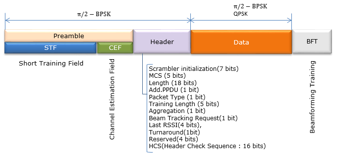
Here is the high-level functionality of this frame:
Preamble: Contains the Short Training Field (STF) and the Channel Estimation Field (CEF), which are used to synchronize the receiver to the signal and estimate the channel conditions, respectively. The preamble prepares the receiver for the data that follows and ensures the accuracy of the signal reception.Header: Provides the receiver with essential information needed to decode the data section of the frame. This includes the modulation and coding scheme (MCS), the length of the data, and other parameters.Data: The main payload of the frame, containing the information intended to be transmitted to the receiver.Beamforming Training (BFT): A section used for beamforming, which is a process to direct the wireless signal towards the specific receiver to optimize the connection quality, especially important in the 60 GHz band where signals have high directionality.
The frame uses π/2 – BPSK modulation for the Preamble and Header to ensure robustness and better range, even at low power, while the Data section can use more advanced modulation schemes like QPSK to increase throughput.
The specific fields in the Header include:
Scrambler Initialization (7 bits): Sets up the initial state of the scrambler to randomize the data, which helps in reducing interference.MCS (5 bits): Defines the data rate and error correction coding.Length (18 bits): Specifies the length of the data payload.Additional PPDU (1 bit): Indicates if there is additional PHY Protocol Data Unit information.Packet Type (1 bit): Distinguishes between different types of packets.Training Length (5 bits): Indicates the duration of the training for beamforming.Aggregation (1 bit): Signifies whether multiple frames are aggregated together.Beam Tracking Request (1 bit): Indicates if beam tracking is needed.Last RSSI (4 bits): Provides the last Received Signal Strength Indicator, which is a measure of the signal power level.Turnaround (1 bit): Indicates whether a switch from transmit to receive is required.Reserved (4 bits): Space reserved for future use or proprietary features.Header Check Sequence (HCS) (16 bits): A checksum for error detection to ensure the header is correctly received.
This header has the same fields as the Single Carrier header above, and it also adds up to 64 bits. The difference between the two frames is in the data part. The Low Power Single Carrier PHY uses simpler coding in the data part to save power at the receiver, and the diagram shows only π/2 - BPSK and QPSK there.
802.11ad OFDM PHY Frame
This is 802.11ad OFDM PHY Frame which carries control information which includes packet type, data length, and other parameters essential for the management and proper routing of the data packet through the network.
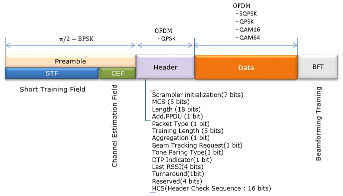
Here is the high-level functionality of this frame:
Preamble: Comprising the Short Training Field (STF) and Channel Estimation Field (CEF), it allows the receiver to lock onto the signal, synchronize, and estimate the channel characteristics.Header: This contains control information that describes how the Data section is encoded and how it should be processed. This includes the modulation scheme, length of the data, and other parameters needed for decoding.Data: The main content of the frame, which carries the actual information to be communicated.Beamforming Training (BFT): A necessary step for the 60 GHz frequency band to optimize the transmission path between the transmitter and receiver, enhancing signal focus and reception.
The modulation schemes shown (π/2 – BPSK for the Preamble, OFDM QPSK for the Header, and SQPSK, QPSK, QAM16 and QAM64 for Data) indicate the type of modulation used for different parts of the frame. The Preamble and Header use a more robust modulation scheme to ensure proper reception under various conditions, while the Data section can use higher-order modulation schemes to increase data throughput.
The detailed components of the Header are as follows:
Scrambler Initialization (7 bits): Provides the initial state for the scrambler to help protect against interference.Modulation and Coding Scheme (MCS) (5 bits): Specifies the data rate and error correction schemes.Length (18 bits): Indicates the length of the Data field.Additional PPDU (1 bit): Signifies if there is more PPDU (PHY Protocol Data Unit) information to follow.Packet Type (1 bit): Distinguishes the packet type for appropriate processing.Training Length (5 bits): Specifies the length of the training field for beamforming.Aggregation (1 bit): Indicates if multiple frames are aggregated together.Beam Tracking Request (1 bit): Signals if beam tracking is needed for maintaining the communication link.Tone Pairing Type (1 bit) and DTP Indicator (1 bit): Used for specifying details about the OFDM sub-carriers.Last RSSI (4 bits): Indicates the last received signal strength to gauge the quality of the received signal.Turnaround (1 bit): Indicates a change from transmit to receive mode, if needed.Reserved (4 bits): Space reserved for future use or proprietary extensions.Header Check Sequence (HCS) (16 bits): A checksum for error detection to ensure the header's integrity.
The OFDM header in the diagram adds up to 7 + 5 + 18 + 1 + 1 + 5 + 1 + 1 + 1 + 1 + 4 + 1 + 4 + 16 = 66 bits. That is two bits more than the 64-bit Single Carrier header. The two extra fields, Tone Pairing Type and DTP Indicator, are drawn next to a Reserved field that still has 4 bits. The field widths on this page have not been checked against the IEEE 802.11ad text. If the OFDM header is also 64 bits, its Reserved field would be 2 bits.
Spectrum Analysis Example
In this section, I will provide a list of snapshots of WLAN RF signals in different formats like spectrogram, power vs time and frequency waveform at a specific point in time. The purpose is to help you with building up some intuitions on how those signal look like. I would not explain the details verbally. I assume that you have a certain degree of understandings on spectrum analysis (i.e, meaning of spectrogram, power vs time and frequency waveform). With this type of basic understanding, try to make sense out of these snapshots by yourselves.
Snapshots on 802.11g
The 802.11g captures are taken on a 2.4 GHz channel centered at 2.412 GHz, which is channel 1, with a 31.25 MHz span. The series starts with a view of several hundred milliseconds and then zooms into one burst in a 250 us window. The pictures after that step a 4 us window through the start of that burst, and the spectrum at the bottom of each picture belongs to that 4 us window.
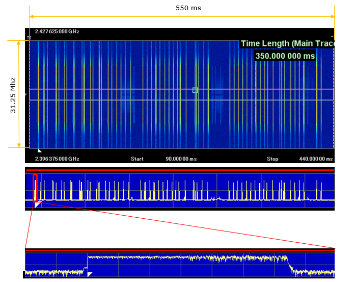
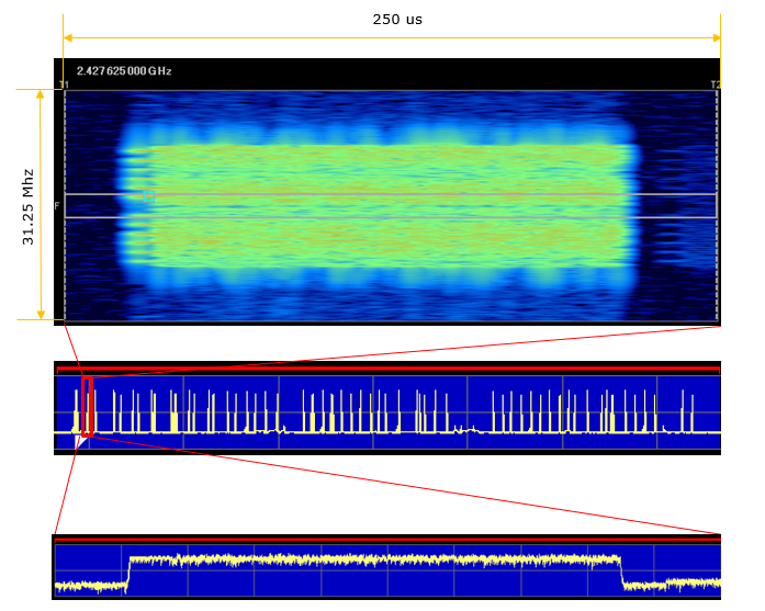
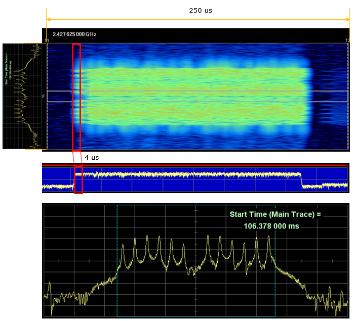
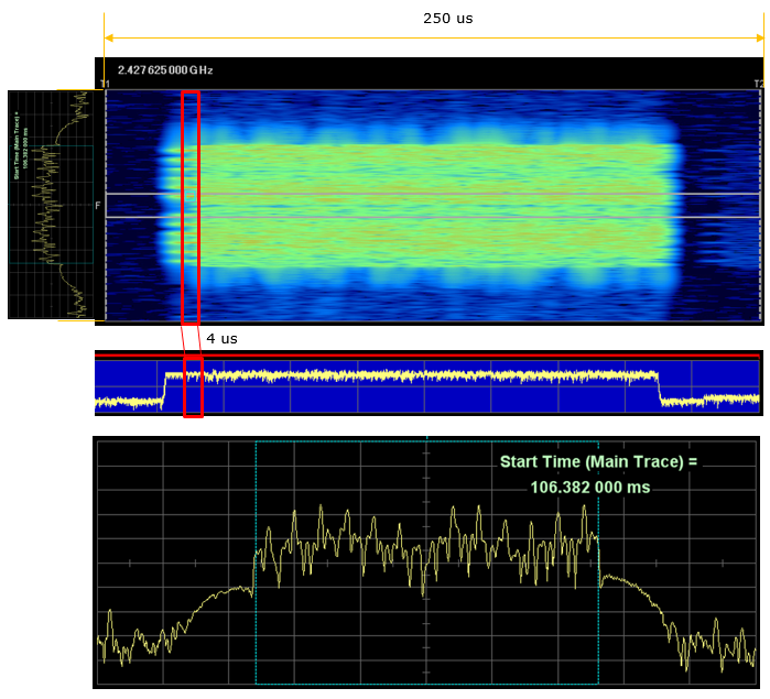
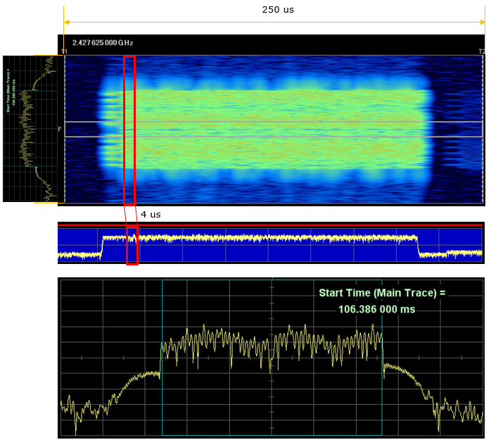
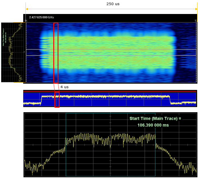
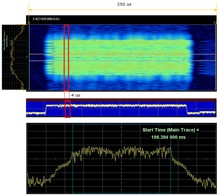
- In the wide view at the top of the series, each vertical line in the spectrogram is one frame. The power vs time trace below it shows the same frames as spikes, and the zoomed trace shows one burst with a flat power envelope.
- In the 250 us view, the burst fills about 16 MHz of the 31.25 MHz span. This matches the 16.6 MHz occupied by 52 subcarriers in the Frequency Domain Structure section.
- The 4 us window at the rising edge of the burst shows a comb of 12 spikes. This is the pattern of L-STF, which uses only every fourth subcarrier, 12 of the 52. Every fourth subcarrier means a 1.25 MHz step, and that repeats the waveform every 0.8 us.
- As the window moves into the burst 4 us at a time, the comb disappears. The spectrum becomes flat and noisy with a small dip at DC, because every occupied subcarrier now carries a symbol.
Snapshots on 802.11n - 20 Mhz
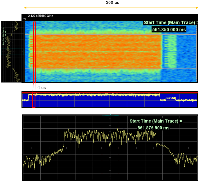
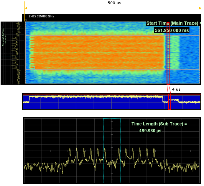
The 802.11n captures use the same channel and span, with a longer 2000 ms view. The zoom picks a long burst that is followed by a short, weaker burst. A 4 us window is then placed at the start of the long burst, twice more about 20 us into it, and finally at the start of the short burst.
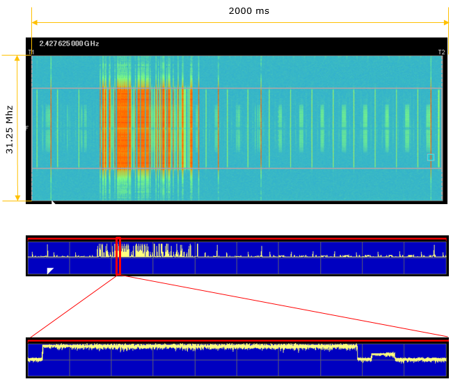
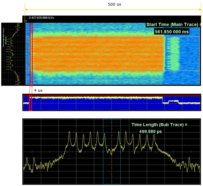
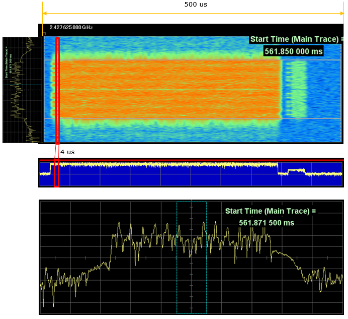
- At the start of the long burst, the window again shows the comb of L-STF. So this 802.11n frame starts with the same legacy preamble as the 802.11g frame, which is the mixed mode format.
- The windows at 561.8715 ms and 561.8755 ms, about 20 us into the burst, show a filled spectrum with no comb.
- The short burst after the gap starts with the comb again, so it is a separate frame with its own preamble. Its lower power and short length suggest an acknowledgement from the receiving device, but the capture alone does not prove this.
A 4 us window is one OFDM symbol : the window matches the 3.2 us symbol plus the 0.8 us guard interval, so each step moves by one symbol.The L-STF comb marks the start of every OFDM frame : when the spectrum shows 12 evenly spaced spikes, the window sits on the short training field.The power vs time trace shows the frame boundaries : the spectrogram shows the bandwidth, and the power trace shows where each frame starts and stops and how long the gap is.
Reference :
[6] 802.11n Tutorial