Protocol
There are a couple of different mode of WLAN operation. Following is the protocol sequence for the case we commonly use where we have an AP(Access Point) and the Device(client PC or Smart phone WLAN) gets connected to the access point.
Overall Procedure
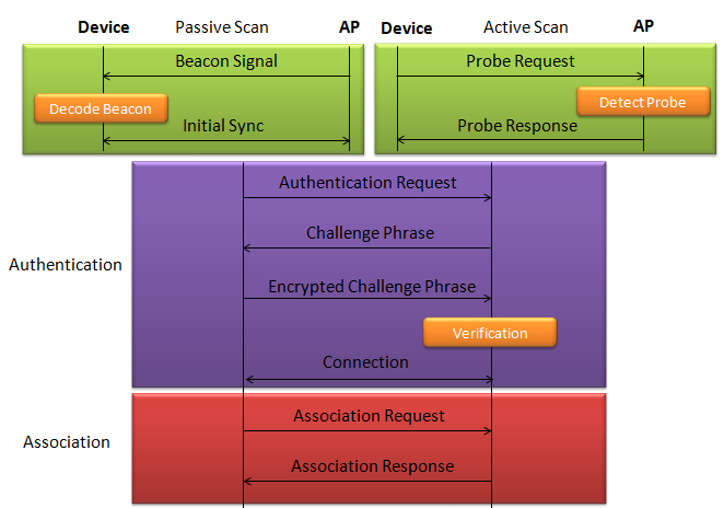
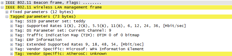
The AP is periodically transmitting (broadcasting) a special signal called Beacon signal saying "I am here.. I am here .. I am capable of this and that .. etc)". Basically this Beacon is like MIB/SIB + Physical Layer Sync channel in mobile communication (e.g, WCDMA/LTE etc). AP broadcast this Beacon several times per seconds. Beacon transmission interval is contained in one of Beacon information fields. (See Beacon data field)
When you turn on WLAN on your PC or Smart phone, the device first detect and decode this beacon signal and establish physical synchronization.
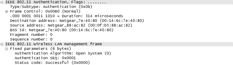
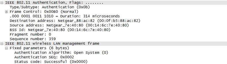
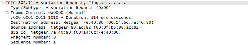
After the physical Sync get established, the device and WLAN network goes through the authentication process and then association process which is similar concept to the registration process in mobile phone communication.
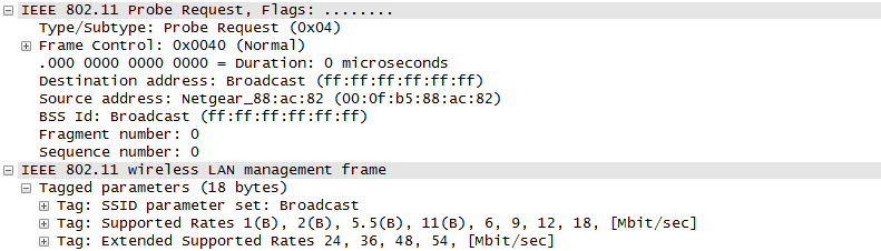
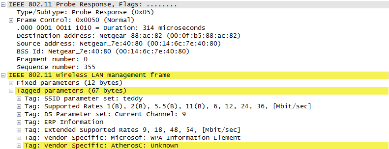
Speaking of scanning, there are two types of scanning. One is called Passive Scan and the other one is called Active Scan. As shown below, in Passive Scan the device scans and detect Beacon signal from AP and establish the sync based on the Beacon signal. In Active Scan mode, device broadcast Probe Request to all the APs (or any specific AP), if there is any AP that detect the probe request, it sends Probe Response to the device.
Once they went through Authentication and Association process, now the device can send and receive user data. Here comes a tricky issues for packet transaction especially when a party tries to transmit something. WLAN does not have concept of dedicated channel (e.g, as in UMTS mobile communication) and it does not have any well designed physical/MAC layer scheduing for each separate user. Basically they are allowed to transmit anytime they like, but in reality a device cannot transmit any time. If it transmit some data while another device is sending data, the data may get lost in the air or it would cause the data for other device get lost since the transmission from the two device would interfer each other. We need some special technique to prevent this problem happening. In Wired LAN, we use a techniq called CSMA/CD and in WLAN we use another technique called CSMA/CA. For the details of these technique, i will write a separate section.. but the goal/purpose of the technique is to make it sure that a device transmit the data when no other device is transmitting anything.
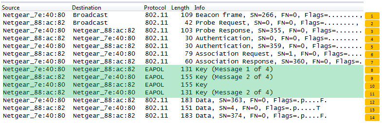
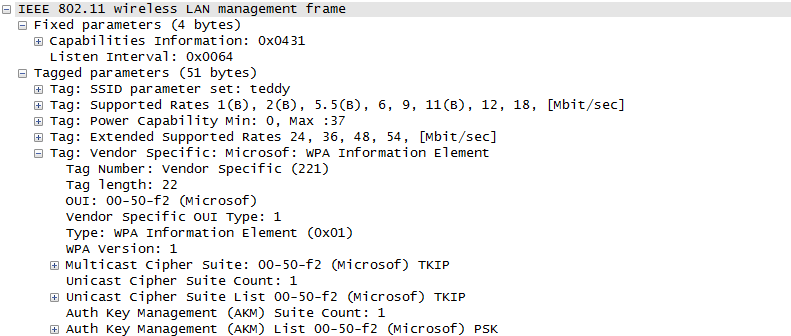
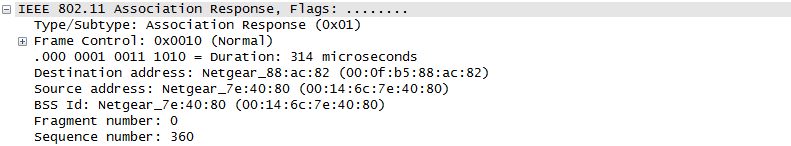
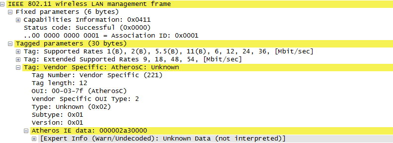
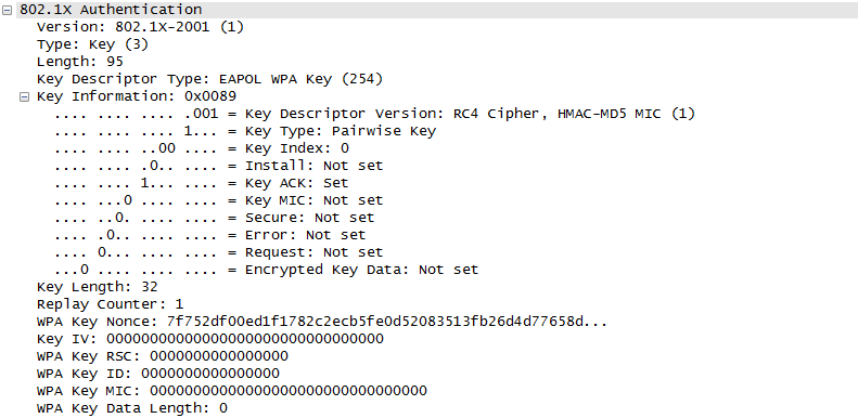
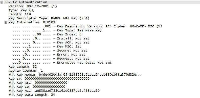
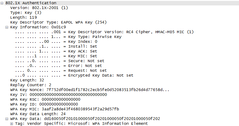
The trace log shown here came from Aircrack-NG Tutorial: WPA Packet Capture Explained. In general, Step (1)~(7) is common to most of WLAN attach process, but the steps after this would be different depending on the security option you set on the device and access point. (Refer to ePDG protocol sequence if you want to see an examples that is different from the step (8) and later)

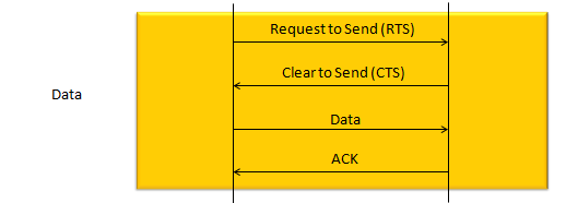
The techniqu that WLAN is using to transmit data without interfering other's is as shown below. The concept is simple. a device (let's call this a source device) send a short signal called RTS to another device (let's call this a destination device). If destination device successfully got the RTS, it is supposed to send CTS. If the source device successfully detect/decode the CTS, it transmit the main data. if the data is successfully recieved/decoded by the destication device, the destination device send 'ACK'. For each and every packet transmission, this process repeats.
Data Transmission in Detail
Once the initial connection setup is completed by the procedure that is explained in previous section, usually the procedure for user data flow starts. In this section, I will go over how the user data flow goes on.
First case is where a chunk of user data is transmitted in single transmission as illustrated below.
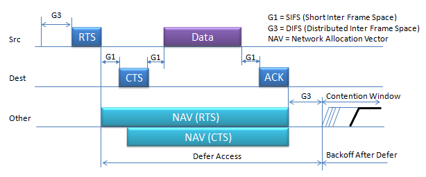
More detailed process of this data tranmission in terms of timing can be illustrated as shown below.
- i) Source transmit the short RTS burst which carries source, destination and duration of following transaction.
- ii) All other devices around the source may receive the RTS burst. They are all checking if the RTS is for itself or not.
- iii) If it is for itself and the medium is free, the destination device transmit the CTS which also carries the duration of following transaction.
- iv) Now all the other device (the neighbouring device other than 'Destination' device) also knows that the medium will be occupied for a certain time from now, they would set their NAV(Network Allocation Vector) accordingly so that it would not try sensing and try to transmit anything during that period.
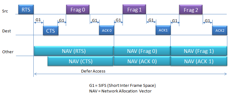
When data packets are larger than the network's Maximum Transmission Unit (MTU) or when the network conditions are such that sending smaller packets is more reliable.Fragmentation in Wi-Fi networks happens. In case of Fragmented Frame, the sequence goes as follows :
-
i) Source (Src) Initiates Transmission:
-
The source device begins by sending a Request to Send (RTS) frame, which includes the source, destination, and the duration of the transmission.
-
ii) Destination (Dest) Responds:
-
If the medium is free, the destination device responds with a Clear to Send (CTS) frame, which also contains the duration of the transaction, indicating that it is ready to receive the data.
-
iii) Fragmented Data Transmission:
-
The source then sends the first fragment of the data (Frag 0).
-
After the destination device successfully receives Frag 0, it sends an acknowledgment (ACK 0).
-
iv) Continued Data Exchange:
-
This process continues with the source sending the next fragment (Frag 1), followed by another acknowledgment from the destination (ACK 1).
-
The sequence repeats for all subsequent fragments (e.g., Frag 2 followed by ACK 2, and so on) until the entire message is transmitted.
-
v)Other Devices Set NAV:
-
Other devices in the network (labeled as "Other") listen to these exchanges and set their Network Allocation Vector (NAV) for the duration indicated in the RTS and CTS frames.
-
The NAV informs these other devices not to attempt transmission and to wait for the medium to become free.
-
vi) Contention Window and Backoff:
-
If any device wants to access the medium, it must wait for a Distributed Inter Frame Space (DIFS) and then proceed to a contention window.
-
During the contention window, each device waits for a random backoff time before attempting to transmit. This helps prevent collisions by randomizing transmission attempts.
It is a short inter frame space that usually happens in some situation as below.
-
Large Packets (G1 Consideration):
-
When dealing with large packets that exceed the MTU, the network must fragment these packets. Between the transmission of each fragment and its corresponding acknowledgment (ACK), the devices observe a short wait time known as a Short Interframe Space (SIFS), labeled as G1 in the diagram. This is the shortest wait time and ensures rapid exchange of frames related to the same data transmission.
-
Poor Network Conditions (G1 Application):
-
In difficult network conditions, such as interference or low signal quality, sending smaller fragments becomes necessary. After sending a fragment, the sending device waits for the duration of G1 (SIFS) before expecting an ACK. If the ACK is received, the next fragment can be sent. This short wait time defined by G1 is crucial for maintaining a quick and orderly flow of the fragmented transmission, allowing for immediate response from the receiving device.
Fragmentation in Wi-Fi networks happens when data packets are larger than the network's Maximum Transmission Unit (MTU) or when the network conditions are such that sending smaller packets is more reliable. The decision to fragment is typically made by the device's network stack, which takes into account the current network conditions, the capabilities and settings of the network devices, and the size of the data being sent.
-
Large Packets:
-
If a data packet is larger than the MTU, which is the largest size of a packet that can be sent in a single frame on a network, the packet needs to be broken down into smaller fragments.
-
Poor Network Conditions:
-
In an environment with a lot of interference, high error rates, or low signal strength, larger packets are more likely to be corrupted. It is often more reliable to send smaller fragments because they have a higher chance of being received correctly.
-
Distance Between Devices:
-
The further the distance between the communicating devices, the higher the likelihood of signal degradation. Smaller packets can be more successfully transmitted over longer distances without error.
-
Regulatory Requirements:
-
Some regulatory bodies may set specific limits on the duration of transmission to ensure fair medium sharing. In such cases, large packets might be fragmented to comply with these "airtime fairness" regulations.
-
Retry Strategy:
-
With fragmentation, if a single fragment is lost or corrupted, only that fragment needs to be retransmitted, not the entire packet. This can reduce the amount of data that needs to be resent and can be more efficient in terms of network bandwidth usage.
-
Dynamic Fragmentation:
-
Some protocols dynamically adjust the packet size based on current transmission acknowledgments (ACKs). If packets are frequently not acknowledged, indicating a high loss rate, the protocol might choose to fragment subsequent packets to improve reliability.
Sleeping Mode and Data Transmission
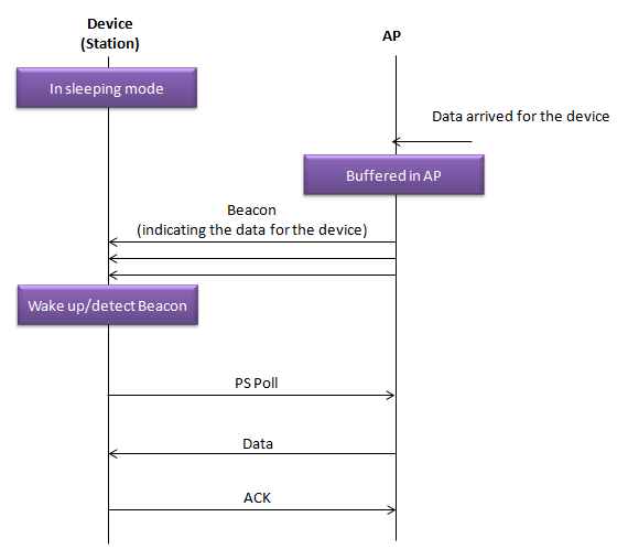
The sequence diagram shown bellow illustrate how a Wi-Fi-enabled device (Station) in power-saving mode communicates with an Access Point (AP) to receive data. This process ensures that devices on a Wi-Fi network can conserve power by sleeping and only waking when necessary to receive data.
Here’s a step-by-step explanation of what’s happening:
-
In Sleeping Mode: The device is in a low-power state, commonly known as sleeping mode, to conserve battery. Data Arrived for the Device: While the device is asleep, data intended for it arrives at the AP.Buffered in AP: Since the device is in sleeping mode, the AP holds onto (buffers) the data instead of immediately sending it.Beacon: The AP regularly sends out beacon frames, which are like lighthouses for Wi-Fi, signaling its presence. These beacons contain a TIM (Traffic Indication Map), which has a bit set if there's data buffered for specific devices.Wake up/detect Beacon: The device periodically wakes up to listen for these beacon frames. When it detects a beacon with a TIM indicating there is data for it, it knows it needs to take action to receive this data.PS Poll: The device sends a Power-Save Poll (PS-Poll) frame to the AP to request the delivery of the buffered data. This is a signal to the AP that the device is awake and ready to receive the data.Data: Upon receiving the PS-Poll frame from the device, the AP sends the buffered data to the device.ACK: After the device successfully receives the data, it sends an acknowledgment (ACK) back to the AP, confirming that the data was received.
Reference :
[1] IEEE 802.11 - Part 11: Wireless LAN Medium Access Control (MAC) and Physical Layer (PHY) Specifications