|
|
|||||||||||||||||||||||||||||||||||||||||||||||||||||||||||||||||||||||||||||||||||||||||||||||||||||||||||||||||||||||||||||||||||||||||||||||||||||||||||||||||||||||||||||||||||||||||||||||||||||||||||||||||||||||||||||||||||||||||||||||||||||||||||||||||||||||||||||||||||||||||||||||||||||||||||||||||||||||||||||||||||||||||||||||||||||||||||||||||||||||||||||||||||||||||||
|
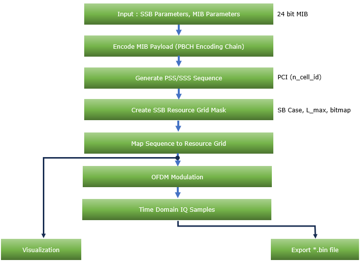
For this note, the script provides a comprehensive 5G NR SSB (Synchronization Signal Block) generator that creates time-domain IQ samples containing fully encoded SSB bursts. The tool generates PSS (Primary Synchronization Signal), SSS (Secondary Synchronization Signal), PBCH (Physical Broadcast Channel), and PBCH DMRS (Demodulation Reference Signal) sequences according to 3GPP TS 38.211 and TS 38.212 specifications. It provides an interactive GUI for configuring SSB parameters, MIB (Master Information Block) content, and exporting binary IQ files suitable for testing SSB detection and decoding tools.
Followings are brief descriptions on each procedure with the focus on sionna api
Toolkits for the scriptI didn't write the code myself. What I did was just prompting for AI tool and did basic check up for the output. Followings are the tool kits that I used for this script
Source Code and OutputYou can get the source code for this note here. I would not describe / explain on every single line of the code since AI (e.g, chatGPT, Gemini etc) will explain better than I do. Disclaimer !!! I have checked and fixed some obvious issues of the script while I am prompting the script, but I haven't verified all the details of the implementation. So there likely to be bugs / errors that I missed. So take this purely as an educational purpose for getting some high level idea on how 3GPP NR Phy specification can be implemented
The script output some part of the result in text and some part in graphics. Followings are the output of the code in text
Followings are the snapshots of graphical output (NOTE : If you want to get images for better resolution, I would suggest you to install the sionna on your PC and run the script that I shared).
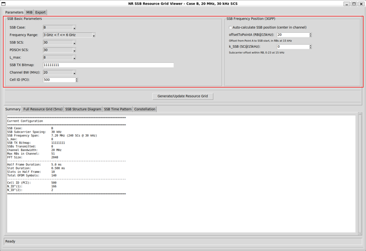
The following parameters define the overall NR carrier context and where the SSB burst is placed inside that carrier. On the left, you select the SSB case and frequency range (which determines the allowed SSB patterns and rules), set the SSB and PDSCH subcarrier spacings, choose L<sub>max</sub> and the SSB TX bitmap to control how many SSBs can appear in a burst and which ones are enabled, and set the channel bandwidth and PCI (Cell ID) that drive the synchronization sequences. On the right, you specify the 3GPP SSB frequency positioning using the Point A reference, including offsetToPointA and kSSB, so the tool can place the 240-subcarrier SSB precisely within the channel grid (or auto-center it) in a way that matches the standard’s resource grid mapping.
Followings are brief descriptions on each parameters
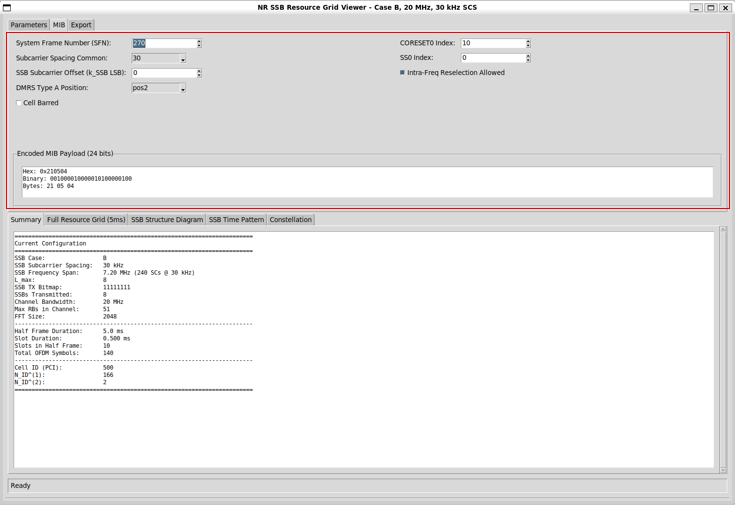
The MIB parameter configures the key MIB (Master Information Block) fields that the gNB broadcasts on PBCH inside the SSB. These parameters describe the cell’s basic frame timing (SFN), the common numerology used for initial access, the SSB’s frequency offset reference, and the control-channel bootstrap information (CORESET#0 and SearchSpace#0) that lets a UE find and decode the first downlink control. It also includes basic access restrictions and mobility hints (cell barred and intra-frequency reselection). The tool then packs these settings into the encoded MIB payload so you can see exactly what will be transmitted.
Followings are brief descriptions on each parameters
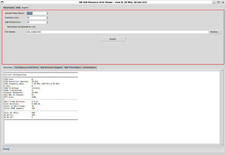
The export parameters define how the tool generates the time-domain IQ output for the SSB burst and how it is saved to a file. You set the sample rate to control the waveform sampling resolution, and you choose the duration to decide how long the generated capture should be. The SSB period configures how often the SSB burst is repeated within that duration. You can optionally normalize the waveform amplitude to a fixed level for consistent scaling. Finally, you specify the output file name (and location) and export the generated binary IQ data.
Followings are brief descriptions on each parameters
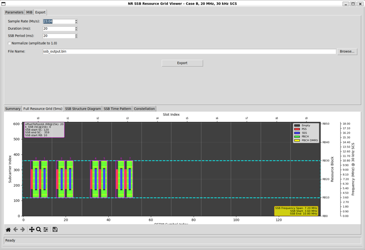
This view gives a high-level summary of how the SSB burst is placed inside the generated NR resource grid over time and frequency. It visualizes where the SSB-related signals (PSS, SSS, PBCH, and PBCH-DMRS) appear across OFDM symbols and subcarriers, so you can quickly confirm the SSB timing pattern, frequency location within the configured channel bandwidth, and overall span of the generated waveform before exporting IQ data.
Followings are the brief descriptions on each components of the plot
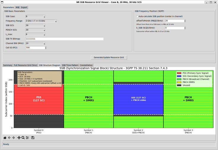
This SSB Structure view illustrates the internal layout of a single Synchronization Signal Block (SSB) on the time–frequency grid, so you can verify that the four OFDM symbols are populated with the correct physical signals per 3GPP mapping. It shows where PSS and SSS are placed for cell search, and where PBCH and its DMRS are placed for broadcasting and enabling coherent PBCH demodulation, making it easy to confirm the expected 240-subcarrier SSB span and the symbol-by-symbol composition before generating or exporting the waveform.
Followings are the brief descriptions on each components of the plot
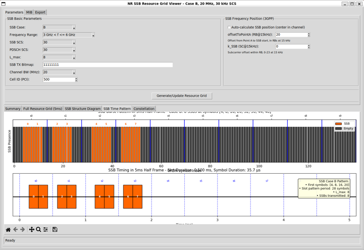
This SSB Time Pattern view summarizes when each SSB is transmitted over time within a 5 ms half-frame, so you can quickly confirm the burst scheduling used for initial access and beam sweeping. It visualizes the slot-by-slot placement of SSBs based on the selected SSB case, subcarrier spacing, Lmax, and SSB TX bitmap, letting you verify the intended SSB periodicity and the exact time locations (slot/symbol windows) where SSBs appear versus where the grid remains empty.
Followings are the brief descriptions on each components of the plot
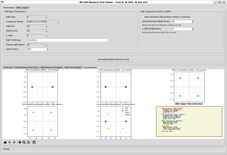
This Constellation view gives a quick sanity check of the modulation mapping used inside the SSB by plotting the ideal I/Q points for each SSB component. By separating PSS/SSS and the PBCH-related signals (PBCH payload and PBCH DMRS), it helps you confirm that each part is using the expected modulation (e.g., BPSK vs QPSK) and that the generated symbols land on the correct constellation points for the selected Cell ID, SSB case, and grid configuration
Followings are the brief descriptions on each components of the plot
Source Code OverviewEven though I no longer need to describe every single line of code in the age of AI, I still think it is valuable to write down some key points. This is not to show off the code itself. It is to record the intention behind the script. I want to clarify what I was trying to do, what kind of idea I had in mind, and what kind of problems this script is designed to solve. This allows the reader to connect the final result with the original design goal. It also helps me later when I come back to this code after a long time and forget my own thinking process. You may not need all of these details if your only goal is to understand the output of the script. For simple usage, you can often treat the script as a black box. You run it. You look at the result. You move on. In many cases this is enough. However, if you want to modify, revise, or extend the script for your own purpose, the situation changes. You would need to know which part of the code is doing what. You would need to know which parameters control which behavior. You would also need to know what kind of assumptions I made when I first wrote the code. In that case, a clear description of the code is not a luxury. It becomes a kind of map. One of the best ways to learn anything related to programming is still very old-fashioned. You break it and then you fix it. You change a small part of the script and see what goes wrong. You check the error. You adjust. You run it again. This loop may look inefficient at first, but it forces your brain to connect cause and effect inside the code. So my intention with these explanations is not just to document the script. It is to give you enough context so that you can safely break it, understand why it broke, and then fix it in a way that matches your own idea. This process is painful sometimes, but it is also the part that makes the knowledge stick to your brain. Key Features
What is Implemented ?Followings are the features that I fully implemented (hopefully :)
What is NOT Implemented ?
Description of Parameters (Global Variables)SSB Configuration Parameters
Channel Bandwidth Configuration
SSB Physical Parameters
Time Domain Configuration
SSB Position Parameters
PBCH Encoding Constants
Cell Configuration
Debug Configuration
Description of FunctionsMIB and PBCH Encoding Functionsencode_mib_payload(self)Encodes MIB information elements into a 24-bit payload per 3GPP TS 38.331. Returns:
3GPP Reference: TS 38.331 Section 6.2.2 encode_pbch(mib_payload_bits, n_cell_id, sfn, ssb_idx, k_ssb_msb, Lmax, n_hf=0)Implements the complete PBCH encoding chain per 3GPP TS 38.211 and TS 38.212, starting from the 24-bit MIB payload and producing 432 QPSK PBCH symbols. Parameters:
Returns:
Processing Steps:
3GPP References:
compute_crc24c(bits)Computes the CRC-24C checksum using a byte-based table lookup method designed to match common reference implementations (e.g., srsRAN). Parameters:
Returns:
3GPP Reference: TS 38.212 Section 5.1 SSB Sequence Generation Functionsgenerate_pss_sequence(n_id_2)Generates the PSS (Primary Synchronization Signal) sequence as a 127-length BPSK sequence derived from n_id_2. Parameters:
Returns:
3GPP Reference: TS 38.211 Section 7.4.2.2.1 generate_sss_sequence(n_id_1, n_id_2)Generates the SSS (Secondary Synchronization Signal) sequence as a 127-length BPSK sequence derived from n_id_1 and n_id_2. Parameters:
Returns:
3GPP Reference: TS 38.211 Section 7.4.2.3.1 generate_pbch_dmrs_sequence(n_cell_id, ssb_idx, Lmax)Generates the PBCH DMRS sequence using a Gold-sequence-based initialization and QPSK mapping for the given cell ID and SSB index. Parameters:
Returns:
3GPP Reference: TS 38.211 Section 7.4.1.4 generate_gold_sequence(length, c_init)Generates a Gold sequence of the requested length using the specified initialization value, typically used for scrambling and DMRS generation. Parameters:
Returns:
Resource Grid Functionscreate_ssb_masks(num_symbols, num_subcarriers, ssb_start_sc, ssb_symbol_positions, ssb_num_subcarriers=None, ssb_scs_ratio=1.0, n_cell_id=0)Creates per-component masks for the SSB region (PSS, SSS, PBCH, PBCH DMRS) so the generator can place each signal on the correct RE locations within the overall resource grid. Parameters:
Returns:
Time-Domain Generation Functionsgenerate_ssb_time_domain(self, sample_rate_hz, num_symbols, fft_size, cp_length, max_subcarriers, ssb_case, l_max, ssb_tx_bitmap, ssb_scs_khz, pdsch_scs_khz, n_cell_id, ssb_period_ms)Generates time-domain IQ samples by mapping SSB components into the resource grid at the configured time/frequency locations, then applying OFDM modulation (IFFT + CP) to produce a continuous complex baseband waveform. Parameters:
Returns:
|
|||||||||||||||||||||||||||||||||||||||||||||||||||||||||||||||||||||||||||||||||||||||||||||||||||||||||||||||||||||||||||||||||||||||||||||||||||||||||||||||||||||||||||||||||||||||||||||||||||||||||||||||||||||||||||||||||||||||||||||||||||||||||||||||||||||||||||||||||||||||||||||||||||||||||||||||||||||||||||||||||||||||||||||||||||||||||||||||||||||||||||||||||||||||||||