Programming in C
Example 1 >
In this example, I will show you how to manipulate the famous GPIO 60 pin using C. If you have never tried playing with the GPIO pin on Beaglebone, I would suggest you try with Shell Programming for GPIO first to get some intuitive feeling of GPIO manipulation.
In terms of final result, this C program would the do exactly the same thing you do in the Shell Programming page. The difference is the way to implement it. In this example, I will operate the GPIO pin by directly manipulating the registers (a kind of special purpose memory) connected to the GPIO. This would be the one of the biggest reason why we use C in stead of other high level tools. The original source code that I refered to is in Ref [2]. But the explanation is in my own words.
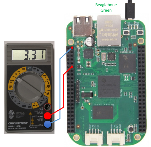
First I connected a voltmeter as shown below (same way and same reason as I did in Shell Progrogramming example).
Before I look into the source code, I will first show you how the program works. It is super simple.
root@beaglebone:/home/jaeku/c/gpio60# ./gpio60 <== Run the program
Value in gpio_oe_addr = 0xEFFFFFFF <== This is the value I assigned to gpio_oe_addr. I will get back to this later
Start toggling PIN
Ctrl + C to quit
Value in gpio_setdataout_addr = 0x10000000
Press Any Key to turn OFF <== At this point (before you pressy any key), you will read 3.3 V on Voltmeter
Value in gpio_cleardataout_addr = 0x10000000
Press Any Key to turn ON <== At this point (before you pressy any key), you will read 0.0 V on Voltmeter
Value in gpio_setdataout_addr = 0x10000000
Press Any Key to turn OFF <== At this point (before you pressy any key), you will read 3.3 V on Voltmeter
Value in gpio_cleardataout_addr = 0x10000000
Press Any Key to turn ON <== At this point (before you pressy any key), you will read 0.0 V on Voltmeter
^C <== Press [Ctrl + C] to quit the program
Following is the source code for this program.
gpio60.c --------------------------------------------------------------------------
#include <stdio.h>
#include <stdlib.h>
#include <sys/mman.h>
#include <sys/stat.h>
#include <fcntl.h>
#define GPIO1_START_ADDR 0x4804C000
#define GPIO1_SIZE 0x1000
#define GPIO_OE 0x134
#define GPIO_SETDATAOUT 0x194
#define GPIO_CLEARDATAOUT 0x190
#define PIN (1<<28)
int main(int argc, char *argv[]) {
volatile void *gpio_addr = NULL;
volatile unsigned int *gpio_oe_addr = NULL;
volatile unsigned int *gpio_setdataout_addr = NULL;
volatile unsigned int *gpio_cleardataout_addr = NULL;
int fd = open("/dev/mem", O_RDWR);
gpio_addr = mmap(0, GPIO1_SIZE, PROT_READ | PROT_WRITE, MAP_SHARED, fd, GPIO1_START_ADDR);
gpio_oe_addr = gpio_addr + GPIO_OE;
gpio_setdataout_addr = gpio_addr + GPIO_SETDATAOUT;
gpio_cleardataout_addr = gpio_addr + GPIO_CLEARDATAOUT;
if(gpio_addr == MAP_FAILED) {
printf("Unable to map GPIO\n");
exit(1);
}
*gpio_oe_addr = (0xFFFFFFFF - PIN);
printf("Value in gpio_oe_addr = 0x%08X\n",*gpio_oe_addr);
printf("Start toggling PIN \n");
printf("Ctrl + C to quit \n");
while(1) {
*gpio_setdataout_addr= PIN;
printf("Value in gpio_setdataout_addr = 0x%08X\n",PIN);
printf("Press Any Key to turn OFF\n");
getchar();
*gpio_cleardataout_addr = PIN;
printf("Value in gpio_cleardataout_addr = 0x%08X\n",PIN);
printf("Press Any Key to turn ON\n");
getchar();
}
close(fd);
return 0;
}
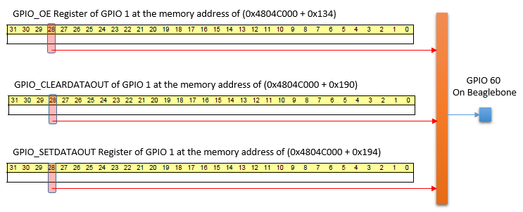
Does this source already make sense to you ? Don't worry even if not the case. The main logic is simple. Each I/O pins on the board is connected to various Registers listed in Table 25-5. GPIO Registers table in Memory Map page. In this example, we will use three registers connected to GPIO 60 pin. Actually not a whole registers are connected to each IO pin. In stead, one specific bit in the register is connected to a specific GPIO pin. In case of GPIO 60 pin, Bit 28 of each register is connected to the pin.
The functionality of GPIO_OE configures the direction of the pin. That is, it determines whether the pin will function as INPUT or OUTPUT pin. If you set the bit to be 1, it makes the pin as INPUT pin. If you set the bit to be 0, it makes the pin as OUTPUT pin.
The functionality of GPIO_SETDATAOUT register is to set '1' to a specific PIN. If you set '1' to the specified bit (Bit 28 in this case), it set HIGH to the GPIO PIN.
The functionality of GPIO_CLEARDATAOUT register is to set '0' to a specific PIN. If you set '1' to the specified bit (Bit 28 in this case), it set LOW to the GPIO PIN.
With this in mind, go through each line of the source code. I think it would make more sense to you if you are familiar with basic C syntax.
Another thing that you should notice is following :
gpio_addr = mmap(0, GPIO1_SIZE, PROT_READ | PROT_WRITE, MAP_SHARED, fd, GPIO1_START_ADDR);
This is to remap a specified physical memory into another memory block (user memory area). Why we do this ? I think it is because most of ARM core does not allow user program to get direct access to the memory blocks for I/O pins. So we make a kind of virtual memory mapped to the physical memory. If we do a certain operation to this virtual memory, it will be automatically reflected to the physical memory (original location)
Reference :
[1] Register access to the GPIOs of the Beaglebone via memory mapping
[2] github: chiragnagpal/beaglebone_mmap (Source Code that I referred to)