'Bearer' in the dictionary means "Carrier" or "Porter" which carries something from a point to another point. Under the context of communication technology, I would define the 'Bearer' as a 'pipe line' connecting two or more points in the communication system in which data traffic follow through.
Taking this definition, we can define 'EPS Bearer' as a pipe line through which data traffic flows within EPS (Evolved Packet switched System).
Four questions follow from that. Where the pipe starts and stops, what it is built from, how it gets configured, and why there is more than one type. The sections below take them in that order.
- Where does an EPS bearer start and end ?
- What is it built from ?
- How does a bearer get configured ?
- Why are there two types ?
- Reference :
Where does an EPS bearer start and end ?
The definition above leaves one question open, and it is the first one to settle. Where does the pipe begin, and where does it stop ? The drawing below answers both, and the far end is closer than most readers expect.
EPS Bearer can be illustrated as the Red path in the following illustration.
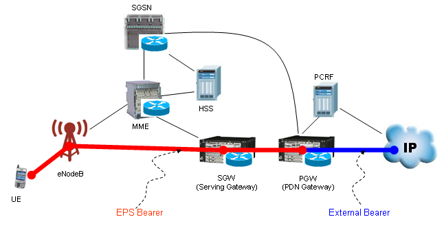
- The red line runs from the UE through the eNodeB to the S-GW and the P-GW, and it stops there. The label
EPS Bearer sits under it in red. - The blue line continues from the P-GW to the IP cloud, labelled
External Bearer . That segment is outside the EPS bearer. - Red dots mark the UE, the S-GW and the P-GW. A blue dot marks the IP cloud, on the far side of the boundary.
- Everything drawn as a thin black line is signalling rather than user data. eNodeB to MME, MME to HSS, MME to SGSN and PCRF to P-GW all sit off the red path.
- The MME appears in the drawing and not on the red line. It sets a bearer up and never carries its traffic.
23.401 draws the same boundary in words. For E-UTRAN access with a GTP-based S5/S8, the PDN connectivity service is provided by an EPS bearer, and that bearer runs between the UE and the PDN GW. The specification names the external bearer beyond it and does not define it.
The purpose is stated just as plainly. An EPS bearer uniquely identifies traffic flows that receive a common QoS treatment between a UE and a PDN GW. The consequence follows immediately. Providing different packet forwarding treatment requires separate EPS bearers, which is the reason a UE ever has more than one.
An EPS bearer ends at the P-GW : the segment past it is the external bearer, which 23.401 names but leaves undefined.The red path carries user data only : the MME sets the bearer up and never carries its traffic, which is why it sits off the line.A bearer is a unit of QoS treatment : 23.401 defines it as the traffic flows that receive one common QoS treatment between the UE and the P-GW.
What is it built from ?
One line on a network diagram turns out to be three bearers laid end to end. The drawing below separates the same path into its segments, and every segment below the top bar belongs to a different pair of nodes.
As shown above, EPS bearer has several components in it. It means EPS beare is a complex of multiple element bearers as in the following diagram.
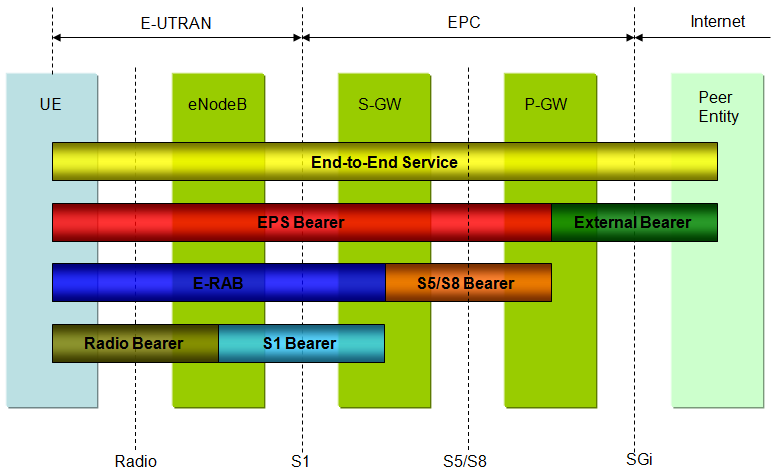
It would seem to be a simple diagram, but as you see EPS bearer includes all the components from Radio Link to the final packet core. It means understanding EPS bearer means understanding the whole LTE network.
I would leave it up to you to study the very details of each component.
If you have any experience or knowledge on the other technology like WCDMA, you can think of EPS Bearer as an entity similar to WCDMA PS Bearer.
- The top bar is the
End-to-End Service in yellow. It reaches from the UE to the Peer Entity and is not a bearer at all. - The second bar splits at the P-GW.
EPS Bearer in red covers UE to P-GW, andExternal Bearer in dark green covers the rest. - The third bar splits at the S-GW.
E-RAB in blue covers UE to S-GW, andS5/S8 Bearer in orange covers S-GW to P-GW. - The bottom bar splits at the eNodeB.
Radio Bearer covers UE to eNodeB, andS1 Bearer covers eNodeB to S-GW. - The dashed verticals along the bottom name the interfaces those splits happen on: Radio, S1, S5/S8 and SGi.
- Read the bars downward and each one refines the bar above it. EPS Bearer is E-RAB plus S5/S8 Bearer, and E-RAB is Radio Bearer plus S1 Bearer.
23.401 clause 4.7.2.2 lists the same elements. A radio bearer carries the packets of an EPS bearer between the UE and the eNodeB. An S1 bearer carries them between the eNodeB and the Serving GW. An S5/S8 bearer carries them between the Serving GW and the PDN GW.
The word to keep from that clause is concatenation. 36.300 defines an E-RAB as uniquely identifying the concatenation of an S1 bearer and the corresponding Data Radio Bearer. An existing E-RAB maps one to one onto an EPS bearer. The drawing writes Radio Bearer where 36.300 writes Data Radio Bearer, which separates it from the signalling radio bearers that carry RRC.
Every join in the chain is one to one, and each node holds one half of a mapping. The UE maps an uplink packet filter to a radio bearer. The eNodeB maps a radio bearer to an S1 bearer. The Serving GW maps an S1 bearer to an S5/S8 bearer. The PDN GW maps a downlink packet filter to an S5/S8 bearer.
That chain is why the paragraph above is right about understanding the whole network. No segment means anything on its own, because each one exists only to pass the same packets to the next.
An EPS bearer is three bearers in a row : a radio bearer, an S1 bearer and an S5/S8 bearer, joined at the eNodeB and at the Serving GW.E-RAB is a name for a pair : 36.300 defines it as the concatenation of an S1 bearer and the corresponding data radio bearer.Every mapping in the chain is one to one : so one EPS bearer means exactly one E-RAB and exactly one data radio bearer, wherever those exist.No single node holds the whole path : the UE, the eNodeB, the Serving GW and the PDN GW each store one link of it and nothing more.
How does a bearer get configured ?
Two different protocols have to agree before any of those segments carries a packet. RRC configures the radio side and NAS configures the core side. LTE arranges for both to reach the UE inside one message, which is what the paragraphs below describe.
If you see the diagram shown above, you would notice that this bearer has two main part. One is 'Radio Bearer' and the other part is Core network bearer.
In UMTS case, the 'Radio Bearer' part is configured by 'Radio Bearer Setup' message and the Core Network Bearer is configured by Activate PDP Context procedure .
In LTE, the both 'Radio Bearer' part and 'Core Network Bearer' both configured by a single message, 'RRC Connection Reconfiguration'. Actually within 'RRC Connection Reconfiguration' message there is one part for Radio configuration and another part for Core Network configuration. See the following two links for the details.
- RRC : RRC Connection Reconfiguration + NAS : Attach Accept + NAS : Activate Default EPS Bearer Context Req
- RRC : RRC Connection Reconfiguration + NAS : Activate Dedicated EPS Bearer Context Request
One field carries the core network configuration. Inside RRC Connection Reconfiguration the NAS message travels in
23.401 makes the same division explicit from the other side. It requires the distinction between default and dedicated bearers to be transparent to the access network. An eNodeB sets up a radio bearer with the QoS it was given, and never learns which kind of EPS bearer that radio bearer belongs to.
Each NAS message names the bearer it concerns. 24.301 puts the EPS bearer identity in bits 5 to 8 of the first octet of every ESM message, which is four bits. The MME selects a value from the range 5 to 15, and uses 0 to say that no EPS bearer identity is assigned.
That range is a real limit rather than a formality. The eleven values from 5 to 15 cap a UE at eleven EPS bearers at once. Both the UE and the MME must support signalling for fifteen EPS bearer contexts before the values 1 to 4 become available.
Two protocols and one message : RRC configures the radio bearer and NAS configures the EPS bearer, and the NAS message travels inside the RRC one.The eNodeB does not know the bearer type : 23.401 requires the default and dedicated distinction to be transparent to the access network.The bearer identity is four bits wide : 24.301 places it in bits 5 to 8 of the first octet of every ESM message.A UE carries fifteen EPS bearers at the most : and only eleven without support for the extended range, because the MME then selects from 5 to 15.
Why are there two types ?
The two lists below are this page's own summary, and 23.401 agrees with most of them. Two lines are worth qualifying, because both are put more strongly here than the specification puts them.
There are two types of EPS Bearer. One is 'Default EPS Bearer' and the other one is 'Dedicated EPS Bearer'. Simply put, we can describe as follows.
i) Default EPS Bearer :
- Be established during Attach Process
- Allocate IP address to UE
- Does not have specifc QoS (only Nominal QoS is applied).
- Similar to Primary PDP Context in UMTS
ii) Dedicated EPS Bearer
- Normally be established during the call setup after idle mode. (but can be established during the attach as well).
- Does not allocate any additional IP address to UE
- Is linked to a specified default EPS bearer
- Have a specific (usually guaranteed) QoS
- Similar to Secondary PDP Context in UMTS
23.401 separates the two by counting rather than by kind. One EPS bearer is established when the UE connects to a PDN, and it stays up for the lifetime of that PDN connection. That one is the default bearer. Any additional bearer on the same PDN connection is a dedicated bearer.
The first line to qualify is the QoS one. A default bearer does carry QoS parameters. 23.401 gives every EPS bearer a QCI and an ARP, GBR and non-GBR alike, and the MME sets the default bearer's initial values from subscription data held in the HSS. What a default bearer cannot have is a guaranteed bit rate, because 23.401 requires it to be a non-GBR bearer.
The second is the mirror of the first. A dedicated bearer can be either a GBR or a non-GBR bearer, in 23.401's words, so a guaranteed rate is available to it rather than usual for it. A dedicated bearer with no guaranteed rate is an ordinary case rather than an exception.
The link between the two is a real information element. 24.301 defines the Linked EPS bearer identity, whose stated purpose is to identify the default bearer associated with a dedicated EPS bearer. That is the mechanism behind the bullet above about being linked to a specified default EPS bearer.
The traffic flow template decides which traffic goes on which bearer, and the Default vs Dedicated EPS Bearer page covers it alongside the message contents.
The difference is ordinal rather than structural : the first bearer on a PDN connection is the default one, and every later one on it is dedicated.A default bearer has QoS but never a guaranteed rate : 23.401 gives it a QCI and an ARP and then requires it to be non-GBR.A dedicated bearer may be GBR or non-GBR : the guarantee is available to it rather than automatic, which is weaker than usually guaranteed.The linkage is signalled and not implied : 24.301's Linked EPS bearer identity names the default bearer that a dedicated bearer belongs to.
Reference :
[1] 23.401 : 3GPP - General Packet Radio Service enhancements for E-UTRAN access, v20.0.0. Clause 4.7.2.1 defines the EPS bearer and the default and dedicated split, clause 4.7.2.2 lists the elements it is realized from, and clause 4.7.3 gives the bearer level QoS parameters.
[2] 24.301 : 3GPP - Non-Access-Stratum protocol for Evolved Packet System; Stage 3, v20.0.0. Clause 9.3.2 gives the EPS bearer identity and clause 9.9.4.6 the Linked EPS bearer identity.
[3] 36.300 : 3GPP - E-UTRA and E-UTRAN; Overall description; Stage 2, v19.2.0. The definitions clause gives the E-RAB, and clause 13 repeats the bearer service architecture from the radio side.
[4] 36.331 : 3GPP - E-UTRA; Radio Resource Control; Protocol specification, v19.3.0. dedicatedInfoNASList carries the NAS message inside RRC Connection Reconfiguration.