Pseudo-Random Sequence (Gold Sequence)
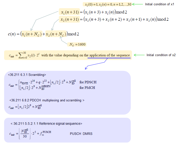
This is not a specific physical channel, but this sequence (variation of the sequence) are used in many way to generate a specific sequence itself (e.g, Downlink Reference Signal) or to scramble the data of a specific channel. The Pseudo-Random Sequence used for LTE is a type of Gold Sequence defined as follows in 36.211 7.2 Pseudo-random sequence generation. (If you are not familiar with the concep of Gold Sequence, refer to Gold Code page)
Followings are the list of topics to be discovered in this page.
- What is this used for ?
- How to implement ?
- Special Chat with Victor : LTE Pseudo Random Sequence in terms of Gold Code Concept
What are we use this for ? There are several different application for this sequence as listed below.
- Generation of Downlink Reference Signal : Two of this Pseudo Random Sequence (Gold Sequence) is used
- Scrambling of PDSCH
- Scrambling of PMCH
- Scrambling of PDCCH
- Generation of PUSCH DMRS (e.g, PUSCH DMRS - 1RB)
I will show you a couple of different ways of implementing this pseudo random sequence here. Depending on the language that you use and your programming style, you would have a little bit different code. Matlab communication package and srsLTE API is verified code, but my MatLab code is not verified but I hope it is written correctly.
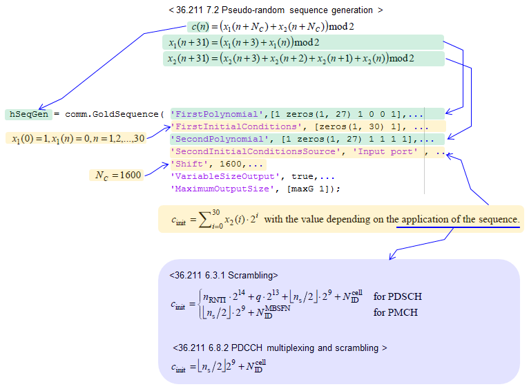
< Matlab Communication Package >
If you have access to Matlab Communication Toolbox, you can implement this sequence as shown below. (This Matlab code clip is from the book : Understanding LTE with Matlab)
Following is the implementation in srsLTE.
void srslte_sequence_set_LTE_pr(srslte_sequence_t *q, uint32_t seed) {
int n;
uint32_t *x1, *x2;
x1 = calloc(Nc + q->len + 31, sizeof(uint32_t));
if (!x1) {
perror("calloc");
return;
}
x2 = calloc(Nc + q->len + 31, sizeof(uint32_t));
if (!x2) {
free(x1);
perror("calloc");
return;
}
for (n = 0; n < 31; n++) {
x2[n] = (seed >> n) & 0x1;
}
x1[0] = 1;
for (n = 0; n < Nc + q->len; n++) {
x1[n + 31] = (x1[n + 3] + x1[n]) & 0x1;
x2[n + 31] = (x2[n + 3] + x2[n + 2] + +x2[n+1] + x2[n]) & 0x1;
}
for (n = 0; n < q->len; n++) {
q->c[n] = (x1[n + Nc] + x2[n + Nc]) & 0x1;
}
free(x1);
free(x2);
}
Following is the Matlab code that I wrote using Matlab default function only. This would be very inefficient at machine level. You may not see this kind of implement at professional code example. But I wrote the code to make it look as closer to the way described in 3GPP document as possible. The purpose of this code is to give you better understanding of the 3GPP spec.
clear all;
% Initial condition of the polynomia x1(). This is fixed value as described in 36.211 7.2
x1_init = [1 0 0 0 0 0 0 0 0 0 ...
0 0 0 0 0 0 0 0 0 0 ...
0 0 0 0 0 0 0 0 0 0 ...
0];
% Initial condition of the polynomia x2().
% This is supposed to be used as c_init as described in 36.211 7.2
% But for simplicity, I just se the arbitrary value for now
x2_init = [0 0 0 0 0 0 1 0 0 0 ...
0 0 0 0 0 0 0 0 0 0 ...
0 0 0 0 0 0 0 0 0 0 ...
0];
% Mpn is the length of the final sequence c()
Mpn = 12*10;
% Nc as defined in 36.211 7.2
Nc = 1600;
% Create a vector(array) for x1() and x2() all initialized with 0
x1 = zeros(1,Nc + Mpn + 31);
x2 = zeros(1,Nc + Mpn + 31);
% Create a vector(array) for c() all initialized with 0
c = zeros(1,Mpn);
% Initialize x1() and x2()
x1(1:31) = x1_init;
x2(1:31) = x2_init;
% generate the m-sequence : x1()
for n = 1 : (Mpn+Nc)
x1(n+31) = mod(x1(n+3) + x1(n),2);
end;
% generate the m-sequence : x2()
for n = 1 : (Mpn+Nc)
x2(n+31) = mod(x2(n+3) + x2(n+2) + x2(n+1) + x2(n),2);
end;
% generate the resulting sequence (Gold Sequence) : c()
for n = 1 : Mpn
c(n)= mod(x1(n+Nc) + x2(n+Nc),2);
end;
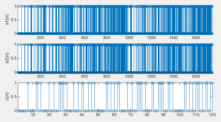
% Following has no meaning in practice, but I just plotted the result just to give you
% overall pattern
subplot(3,1,1);
stem(x1);xlim([1 length(x1)]); ylabel('x1(n)');
subplot(3,1,2);
stem(x2);xlim([1 length(x2)]); ylabel('x2(n)');
subplot(3,1,3);
stem(c);xlim([1 length(c)]); ylabel('c(n)');
Following is the code written by Victor Ivanov (vic.m.ivanov[at]gmail.com ) and shared here with permission by him. Depending on your background, it may be a little bit difficult to understand comparing to the two other examples shown above. But in terms of shift register logic this code would be more relavant. That is, this code would better represent the hardware implementation of the sequence.
Following is the comments from Victor when he was sharing the code with me. I always like to read some comments from experts, coming directly out of his mind without considering much on formal writing. Once we try thinking of formal writing, it tend to dry and less lively :). I hope this give some insight for other readers as well.
Having looked at the examples, it struck me that both the Matlab as well as the one from srsLTE, while easy to understand, use a lot of memory as they allocate space for at least (Nc + Mpn) to perform the computation after which only the last Mpn elements are taken into account. They both make use of traditional additions making them slow. You've already put a disclaimer on that so that's ok. But more importantly, with the hardware based implementation of gold sequence generation using LFSRs (explained here: GoldCode ) initially I found it difficult to relate how the 3GPP examples fit together with the LFSR logic.
So I thought you might be interested in adding the following C function that I quickly drafted to your page for the scrambling sequence generation. It can allocates memory for only Mpn bits and works entirely with bitwise operations making it at least twice and up to several times faster to compute the scrambling sequence 'c'.
#include <stdint.h>
#include <stdlib.h>
uint8_t* generate_sequence(uint32_t seed, uint32_t length) {
int Nc = 1600;
int n;
uint32_t x1, x2; // m-sequence 'registers'
uint32_t x1_fb, x2_fb; // LFSR feedback values
uint8_t *c;
c = malloc(length * sizeof(uint8_t));
x1 = 0x1;
x2 = seed;
for (n = 0; n < Nc + length; n++) {
if (n >= Nc) {
// Only start taking values for 'c' after seeding
c[n - Nc] = (x1 ^ x2) & 0x1;
}
// Advance the 1st m-sequence
x1_fb = ((x1 >> 0) ^ (x1 >> 3)) & 0x1;
x1 = (x1 >> 1) | (x1_fb << 30);
// Advance the 2nd m-sequence
x2_fb = ((x2 >> 0) ^ (x2 >> 1) ^ (x2 >> 2) ^ (x2 >> 3)) & 0x1;
x2 = (x2 >> 1) | (x2_fb << 30);
}
return c;
}
Special Chat with Victor : LTE Pseudo Random Sequence in terms of Gold Code Concept
I had some chat with Victor in email about LTE Pseudo Random Sequence in terms of Gold Code Concept and I thought the comment / explanation can be helpful (very practical explanation) for other readers, especially for the person like me who is not a real expert on this low layer implementation. So I decided to share the chat here with his permission of course.
[Victor] (...) it's not immediately obvious why it works and how it fits with the Gold Sequence LFSR diagram",
[Sharetechnot] Sorry if I confused you, in my understanding LFSR, m-Sequence, Gold Sequence is a TYPE of sequence generation algorithm which has a certain kind of characteristics, they do not indicate any specific sequence of numbers.
Gold Sequence is generated by combining two m-Sequence (m-Sequence is a type of LFSR) as illustrated in my Gold Sequence page (number of shift register and wiring may vary as long as it meets a certain set of characterstics).
In LTE PRS, I think c[] is a type of Gold Sequence which is made up of two m-Sequence (x1[], x2[]).
[Victor] No problem at all. I too have mostly been using it to understand / study it. My research is actually in computer microarchitecture for 5G. It's difficult to say how it's currently implemented in real hardware as a lot of it is proprietary information of chip manufacturers and hardly any of it is available in the public domain.
Your understanding of the Gold Sequence is correct. My confusion did not come from your Gold Code diagram itself, but the question I was trying to answer to myself was "How do I implement the LTE sequence generator as gold code in hardware with LFSRs?". Which was difficult to answer from the Matlab and srsLTE code as they do not describe LFSR logic but rather in-memory computation of arrays.
But since Gold Code does, in fact, combine two m-sequences to generate the Gold sequence and each m-sequence can be easily implemented (in hardware) with a linear feedback shift register (LFSR), like the two on your Gold Code page. And the way we describe which individual bits are used in the feedback logic of the LFSR is by generator polynomials. In fact, it's the generator polynomials that tells us exactly what the wiring of the LFSR is. In the 3GPP LTE PHY specs, the two equations for x1(n+31)=... and x2(n+31)=... essentially describe (in a non-obvious way) the two generator polynomials for the two m-sequences that the LTE Gold Code generator uses:
G(m1) = x^3 + 1 (derived from x1(n+31)=...)
G(m2) = x^3 + x^2 + x^1 + 1 (derived from x2(n+31)=...)
Once we know these, along with the fact that in 3GPP LTE the two m-sequences are 31 bits wide (as specified in chapter 7.2) we can go back to your Gold Code circuit diagram and create the same diagram with 31 [D] cells (each [D] cell stores a single bit) and making our feedback wiring based on based on the above generator polynomials (see attached diagram for the LTE Gold Code generator).
You could have different wiring and it would still produce a valid Gold Code sequence, but if the wiring is different it will produce a different sequence. Thus, there can only be one exact wiring in LTE that can be used which is described by the above generator polynomials.
But to have the circuit actually generate any bit sequence at all it must have an initial value. For example, if the Gold Code circuit that you have on your page had a value of 0 stored in each [D] cell for both the top and bottom LFSR, then the output for c[n] will always be 0, regardless of how many clock cycles pass and it won't generate any sequence at all.
This is why 3GPP specifies the _initial_ values for the m1 and m2 sequences. Assuming the LTE PRS generator is implemented with two shift registers (as in your Gold Code diagram), the initial value for the 1st m-sequence LFSR is always set to 0x1, meaning that all the left-most 30 [D] cells of the shift register will hold a value of 0, and the right-most [D] cell will have a value of 1.
The _initial_ value of the 2nd m-sequence LFSR is the binary value for c_init which varies for each channel (xPDSCH, xPDCH, etc) and device, and the way it's computed is described in the specs for each channel.
And before we start taking the values for c[n] we let the circuit shuffle around for Nc=1600 cycles to induce extra randomness for the initial state. We can then start taking the bit values coming out of the circuit for c[n].
The example binary number (00...101101) that I gave in my previous email is completely arbitrary and not related to LTE specifically, but it serves well to demonstrate how the code works and how it relates to the Gold Code circuit that you have (which for me was difficult to comprehend initially). And since the code uses binary shift operators, we can immediately see how the two real shift registers of the Gold Code generator would behave (if implemented with LFSR logic).