|
|
|||||||||||||||||||||||||||||||||||||||||||||||||||||||||||||||||||||||||||||||||||||||||||||||||||||||||||||||||||||||||||||||||||||||||||||||||||||||||||||||||||||||||||||||||||||||||||||||||||||||||
|
Frame StructureAs you may noticed from other technology that I posted, the way I study about a communication technology is always same. Study and understand the details of frame structure and then understand how these frames are exchanged at each step of communication process (protocol).
Overview of WLAN FrameFollowings are some of the bullelts for WLAN Frame. (The list would get longer as I learn more)
PHY/MAC FrameThis is the frame being exchanged between the mobile device and Access point. The overall frame is structed as shown below. The 'Network Data' shown in Green is the part which are eventually eventually conveyed to wired backbone and all the other portion (PHY, DataLink, Packet Trailer) are used for communicating between the mobile client and access point. PHY and 'Data Link' part will be main subject of WLAN frame.
PLCP (Physical Layer Convergence Protocol) StructureNow let's look into the details of PLCP. PLCP is a kind of header deing added at PHY layer. It consists of two main parts, preamble and Header as shown below.
The first part of PLCP is for 'Sync' (Synchronization). This is a part made of 80 bits of alternation 0 and 1s. The next portion is SFD (Start Frame Delimiter). This is a kind of tag indicating the start of physical frame and it is a specifically determined 16 bit sequence (0000110010111101). MAC Header StructureMAC Header would be a most complicated structure of the frame. The most important information contained in the MAC header would be as follows.
Frame Control Field Structure
You see four different locations allocated for Address. What kind of address is assigned to which address field is determined by 'To DS' and 'From DS' field. The mapping between DS field and Address field are specified as follows.
Regardless of the contents in the frame, the structure of MAC header is same. Then how do we (the WLAN device) knows what kind of the information (data) is contained in the frame. 'Type' and 'Sub Type' field determines the characteristics of the frame. Type field (2 bits) determines the major characteristics of the contents carried by the frame and 'Sub type' defines the details of the information. The 'Type'/'Sub Type' and characteristics of the contents are mapped as shown in the following table. This table is mostly for 802.11 a,b,g and there is some changes (additions) in recent specification (e.g, 802.11ac, 802.11ad). Regarding the changes in recent specification, I would not list in this table and I will list those changes in separate pages dealing with 802.11ac or 802.11ad. Frame Type Table
Duration ID Field StructureThe value in the duration field has different meaning (interpretation) depending on the one or two bits at Most Significant Bits (MSB) as shown below.
Sequence Control Field StructureWhen a packet comes into the MAC layer from higher layer, a sequence number is assigned at 'Sequence Number' field. If the incoming packet is too big for a single MAC frame, it be splitted into multiple fragment. In this case, a fragment number is assigned at 'Fragment No' field. When a packet gets into multiple MAC frame, those fragmented frame gets the same value at 'Sequence Number' field and different values at 'Fragment No' field. 802.11 can transmit the max 2304 bytes of higher layer packet. Considering WEP overhead and 8 bytes LLC header, the maximum MAC frame size should be 2296 bytes.
RTS Frame
CTS Frame
ACK Frame
Beacon Frame
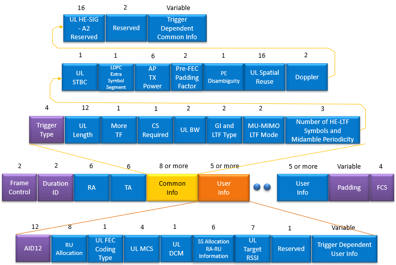
The contents of the Beacon Frame (Beacon Body) is a huge structure, so I created a separate page for Beacon and it's contents. Trigger Frame
NOTE : Log file is from Gjermund Raaen who kindly allowed me to share the log clips.
Reference
|
|||||||||||||||||||||||||||||||||||||||||||||||||||||||||||||||||||||||||||||||||||||||||||||||||||||||||||||||||||||||||||||||||||||||||||||||||||||||||||||||||||||||||||||||||||||||||||||||||||||||||