Massive MIMO has been a key component for achieving such a high throughput promised by 5G/NR. So you may guess that Enhancement of Massive MIMO would be for even higher throughput, but it is not. In terms of throughput, we already have almost all the capability with Release 15. We already got max 8 CC CA in FR2 and 256 QAM. The only remaining technology to push up the throughput even further would be 2 codewords in both FR1 and FR2, 8 layers in FR1 and 400 Mhz bandwidth in FR2, but it doesn't seem to be the target for Release 16.
- Multi TRP (Transmission and Reception Point)
- How is a Multi-TRP transmission scheduled ?
- Codebook Type II Enhancement
- What does the Enhanced Type II codebook actually change ?
- PDSCH DMRS
- What changed in beam management ?
- What happened after Release 16 ?
- RRC Parameters
- UE Capability Information
- Reference
Major focus for Release 16 is to increase the stability of MIMO connection and more robust recovery process for beam failure.
The list of the feature to enhance Massive MIMO in Release 16 in comparison to Release 15 is described as follows in RP-200474 and Ref [1].
|
Release 15 |
Release 16 |
|
Support of Beam-Based Operation |
|
|
CSI codebook : Upto 32 ports |
|
|
CSI Type I Codebook : Basic Closed Loop MIMO |
|
|
CSI Type II Codebook : High Resulution, MU-MIMO |
Enhanced Type II Codebook
|
|
|
Multi-TRP/Multi-Panel transmission enhancements
|
|
|
Multi-beam operation enhancement
|
|
|
Low PAPR Reference Signal
|
Multi TRP (Transmission and Reception Point)
One of the most frequently mentioned feature related to enahanced massive MIMO would be the featured called Multi TRP. This is a feature that enable gNB to use more than one TRP to communicate to a UE. There are a couple of different ways for this type of communication and it can be summarized as in the following illustration.
(A) TRP1 and TRP2 is transmitting two two different PDSCH but control signal (PDCCH/DCI) for the two PDSCH is transmitted by TRP1. In this case, if there is some problem in radio link with TRP1 and PDCCH reception fails, the communication via TRP2 is impacted as well.
(B) TRP1 and TRP2 is transmitting two two different PDSCH and each TRP is transmitting its own corresponding PDCCH/DCI. In this case, if there is any problem in radio link with one of the TRPs, the communication via other TRP can be intact.
(C) This scenario shows the case where TRP1 and TRP2 is used to jointly process the DL and UL signal (Similar scenario as CoMP)
Three arrangements are drawn, and the arrows are what separate them. In (A) both TRPs send a PDSCH, and both PDCCH beams originate at TRP1. In (B) each TRP sends its own PDCCH beside its own PDSCH, so the two orange cones sit on different towers. In (C) there is no PDCCH drawn at all, and a single blue arrow reaches the UE from each TRP.
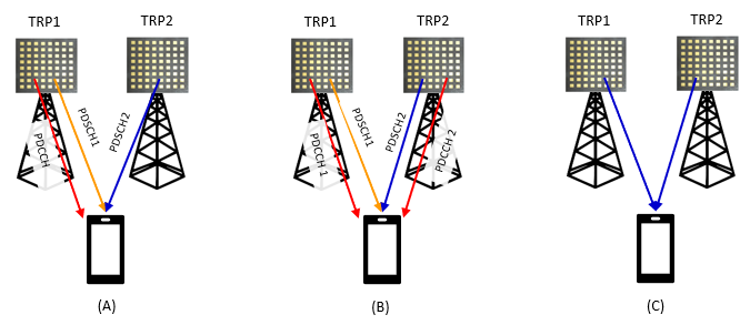
Figure 1. The difference that matters is which TRP sends the control channel. In (A) one failed PDCCH costs both data streams, and in (B) it costs one.
How is a Multi-TRP transmission scheduled ?
The three pictures above have names in 3GPP, and the names are more useful than the letters. I read single-DCI and multi-DCI in specifications for a long time without connecting them to this diagram. (A) is single-DCI multi-TRP, (B) is multi-DCI multi-TRP, and (C) is joint transmission.
In the single-DCI case there is one PDCCH and one DCI, so the UE has to learn from that one DCI that two TRPs are involved. It learns it from the TCI field. A TCI codepoint can be configured to map to two TCI states rather than one, and two TCI states means two sources. Nothing else in the DCI changes.
In the multi-DCI case the two TRPs schedule independently, so the UE has to keep the two apart. It does that by CORESET. Each CORESET carries a CORESETPoolIndex, and CORESETs with different values belong to different TRPs. The UE then maintains separate HARQ processes and separate feedback for each.
Single-DCI multi-TRP is mostly used for reliability rather than for throughput, and Rel-16 defines four ways to use the second TRP for repetition. They differ in whether the copies are separated in space, in frequency or in time.
|
Scheme |
Copies separated in |
What the UE receives |
RRC |
|
SDM |
space, using layers |
one transmission, with the layers split between the two TCI states |
two TCI states and no repetition scheme configured |
|
FDM scheme A |
frequency |
one redundancy version, spread across two frequency allocations |
repetitionScheme-r16 = fdmSchemeA |
|
FDM scheme B |
frequency |
two redundancy versions, one in each frequency allocation |
repetitionScheme-r16 = fdmSchemeB |
|
TDM scheme A |
time, inside one slot |
two transmissions in the same slot, offset by startingSymbolOffsetK |
repetitionScheme-r16 = tdmSchemeA |
|
TDM scheme B |
time, across slots |
one transmission per slot, over several slots |
slotBased-r16, with tciMapping and repetitionNumber |
The ordering in that table is also an ordering in latency. SDM costs nothing in time and gives the least diversity, because both copies meet the same instant of the channel. Inter-slot TDM gives the most diversity and costs the most time. A URLLC deployment usually wants the bottom of the table, and a throughput deployment usually wants the top.
Two TCI states in one codepoint is the single-DCI signal : Nothing else tells the UE that two TRPs are transmitting. The TCI field carries it.CORESETPoolIndex is the multi-DCI signal : Different values mark different TRPs, and the UE keeps HARQ and feedback separate for each.The repetition schemes trade latency for diversity : SDM is the fastest and the weakest. Inter-slot TDM is the slowest and the strongest.FDM scheme A and B differ only in redundancy version : Scheme A sends one version across both allocations. Scheme B sends a different version in each.Rel-16 caps this at two TRPs : The feature is written for two transmission points, not for an arbitrary number of them.
Codebook Type II Enhancement
This is not a new feature. It is an enhanced feature for an existing feature. Type II codebook is already there in Release 15. Then what will be changed in Release 16 ? Unfortunately it is not each to precisely point out the difference unless you look into the codebook equation itself.
- Number of supported layers is increased from 2 (Rel 15) to 4 (Rel 16).
- Codebook itself will get more sophisticated in Rel 16 comparing to Rel 15. This would not look obvious unless you analyze the codebook equation to the very detailed level. I did this analysis in my codebook page. If you take a close at the equation and compare it to Rel 15 equation, you would notice that the granularity of amplitude and phase parameter is improved in Rel 16.
The upper table is the Rel-15 Type II codebook and the lower one is the Rel-16 enhancement, both quoted from 38.214. Two differences are visible without reading the subscripts. The Rel-15 table stops at v=2 and the Rel-16 table runs to v=4. The Rel-15 expression has a single sum over i, and the Rel-16 expression has a double sum, over i and over f.
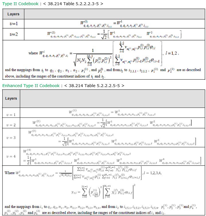
Figure 2. That second summation index is the whole enhancement. It is the frequency-domain basis, and it is what turns a per-subband report into a compressed one.
This is the same comparison for the port selection codebook, from Table 5.2.2.2.4-1 and Table 5.2.2.2.6-2. The pattern repeats exactly. Rel-15 covers v=1 and v=2 with a single sum, and Rel-16 covers v=1 to v=4 with the same double sum over i and f. The normalisation term gamma appears in the Rel-16 version and not in the Rel-15 one.
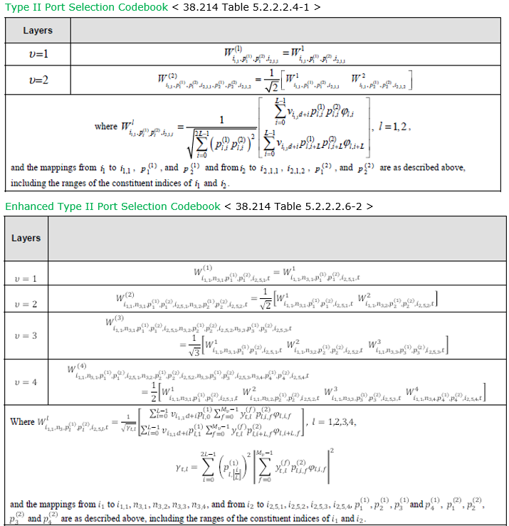
Figure 3. Port selection gets the same treatment. The compression is applied to both Type II variants rather than to one of them.
What does the Enhanced Type II codebook actually change ?
The section above says it is hard to point out the difference without reading the equation. The two figures do point it out, and it is one summation. You do not have to follow the subscripts to see it.
Rel-15 Type II builds a precoder from L beams. For each beam the UE reports an amplitude and a phase, and it reports them for every subband. The report therefore grows with the number of subbands, and Type II was already the most expensive feedback in NR. That cost is what limited it to rank 2.
Rel-16 adds a third stage. Instead of reporting a coefficient per beam per subband, the UE projects the frequency variation onto a small DFT basis of M vectors. It then reports coefficients in that compressed domain. The extra sum over f in Figure 2 is that projection. Most of the coefficients are then zero, and the UE reports only the ones that are not, together with a bitmap saying which.
Two consequences follow. The feedback shrinks, because the report no longer scales with the subband count in the same way. The saving is then spent on rank, which is why the Rel-16 table runs to v=4 while the Rel-15 table stops at v=2. Higher rank is what MU-MIMO needed.
The change is compression, not a new beam structure : The L beams are unchanged. What changed is how their variation across frequency is reported.The second summation index is the whole difference : Rel-15 sums over beams. Rel-16 sums over beams and over a frequency basis.Sparsity is the reason it works : The compressed coefficients are mostly zero, so a bitmap plus the non-zero values is smaller than a per-subband report.The saving is used for rank : Rel-15 Type II stops at rank 2. Rel-16 reaches rank 4, and that is what MU-MIMO scheduling wanted.Port selection gets the same treatment : Figure 3 shows the identical change applied to the port selection codebook.
PDSCH DMRS
A new DMRS sequence is introduced in release 16 mainly which can be summarized as below.
Two versions of the same initialisation are stacked, and only c_init differs. The Rel-15 expression uses n_SCID directly. The Rel-16 expression replaces it with a value that carries a lambda superscript, and it adds a floor of lambda over two as a separate term. The notes below define lambda as the CDM group, and they give one rule for when DMRS-DownlinkConfig.dmrs-Downlink is configured and another for when it is not.
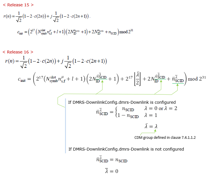
Figure 4. The Rel-16 sequence depends on the CDM group. Two CDM groups therefore no longer share one scrambling sequence, which is what multi-TRP needs when each TRP owns a different group.
What changed in beam management ?
The table at the top of this page lists three beam management items and the page never returns to them. They matter more than the codebook work for most deployments, because they decide what happens when a beam fails rather than how well it performs while it works.
The first is beam failure recovery on a secondary cell. In Rel-15 the recovery procedure existed only on the cell that carries the random access resources. A failed beam on an SCell therefore had no dedicated recovery at all. Rel-16 adds beamFailureRecoverySCellConfig, and the request travels as a MAC CE on a serving cell that still works rather than as a PRACH preamble.
The second is L1-SINR. Rel-15 measured beams by L1-RSRP, which says how strong a beam is and nothing about what else is arriving at the same time. Rel-16 adds cri-SINR and ssb-Index-SINR as report quantities. In an interference limited cell the strongest beam and the most usable beam are often not the same beam, and RSRP cannot tell them apart.
The third is latency and overhead in beam switching, which is less a single feature than a set of small reductions. The direction is the same throughout Rel-16 eMIMO. Keep the beam management machinery and make it react faster.
SCell beam failure recovery was missing before : A Rel-15 UE could lose an SCell beam with no dedicated way to report it. The Rel-16 request is a MAC CE, not a preamble.RSRP measures power and SINR measures usability : Adding cri-SINR and ssb-Index-SINR lets the network pick a beam with less interference rather than merely more power.This is the stability half of the release : The codebook work raises throughput. The beam management work keeps the link working, and the page opening says that is the Rel-16 focus.
What happened after Release 16 ?
The comparison table at the top of this page runs from Rel-15 to Rel-16, and MIMO did not stop there. Three releases have followed, and each moved the work somewhere different. I find the releases easier to keep apart by what they were trying to fix than by the feature lists.
Rel-17 targeted the indication machinery rather than the radio. By the end of Rel-16 a UE could be told about beams in several different ways, one per channel, and separately for downlink and uplink. The unified TCI framework replaces that. A single TCI state applies across channels, and unifiedTCI-StateType-r17 says whether downlink and uplink share one state or keep two, with the values joint and separate. Rel-17 also let a TRP carry a different physical cell identity, through additionalPCI-r17, which is what made inter-cell multi-TRP possible. PDCCH gained repetition across two TRPs, and the further enhanced port selection codebook arrived as typeII-PortSelection-r17.
Rel-18 reworked the codebook, and stopped treating it as one thing. Two new Type II variants appeared, each shaped for a case the Rel-16 codebook handled badly. typeII-CJT-r18 is for coherent joint transmission. Several TRPs transmit the same layers there, and their phases have to be aligned. typeII-Doppler-r18 is for UEs moving fast enough that the channel ages between report and use. The uplink also got a codebook of its own in CodebookTypeUL-r18, alongside the work on eight transmit antennas. Unified TCI was extended across carriers and cells, with UL-TCI-AcrossCC-r18 and UL-TCI-AcrossCells-r18.
Rel-19 is still arriving, and the names in the ASN.1 point in two directions. One is prediction, in CodebookParametersCSI-PredictionDoppler-r19 and CodebookParametersType2DopplerExt-r19, which continue the Rel-18 attempt to report a channel that will still be current when it is used. The other is reporting control, in CSI-ReportUE-Initiated-r19, where the UE rather than the network decides that a report is worth sending. Hybrid beamforming codebooks appear as well, in CodebookParametersHybridBF-eType2-r19.
|
Release |
What it was trying to fix |
Representative RRC |
|
Rel-15 |
make MIMO work at all |
CSI Type I and Type II, up to 32 CSI-RS ports |
|
Rel-16 |
make the link stable |
RepetitionSchemeConfig-r16, beamFailureRecoverySCellConfig-r16, typeII-r16 |
|
Rel-17 |
unify how beams are indicated |
unifiedTCI-StateType-r17, additionalPCI-r17, typeII-PortSelection-r17 |
|
Rel-18 |
fit the codebook to the case |
typeII-CJT-r18, typeII-Doppler-r18, CodebookTypeUL-r18 |
|
Rel-19 |
predict the channel, and let the UE ask |
CodebookParametersCSI-PredictionDoppler-r19, CSI-ReportUE-Initiated-r19 |
One thread runs through all of it. Rel-15 gave the network a very good description of the channel and charged a great deal of feedback for it. Every release since has been trying to pay less for that description, or to keep it accurate for longer. Compression did the first, in Rel-16. Doppler and prediction are doing the second.
Rel-17 is about indication, not about the radio : The unified TCI framework replaces several separate beam indications with one state, and unifiedTCI-StateType-r17 chooses joint or separate for downlink and uplink.Inter-cell multi-TRP needed a second cell identity : additionalPCI-r17 lets a TRP use a different physical cell ID. The Rel-16 multi-TRP design had no way to express that.Rel-18 split the codebook by use case : Coherent joint transmission and high Doppler each got a Type II variant of their own, rather than one codebook stretched to cover both.The uplink got a codebook of its own in Rel-18 : CodebookTypeUL-r18 gave the uplink its own codebook type, alongside the move to eight transmit antennas.The direction is cheaper CSI that stays true for longer : Compression reduced what a report costs. Doppler and prediction extend how long a report stays true.
RRC Parameters
The features above are configured by a small number of information elements, and they are easier to read together than scattered through 38.331. Each block below is quoted from the newest release dump on this site that carries it, and the release is named beside the heading. An element that has not changed since its introduction therefore still shows its original release.
This is the multi-TRP repetition configuration described earlier on this page. The CHOICE is the important part. fdm-TDM covers the schemes that fit inside one slot, and slotBased covers repetition across slots.
RepetitionSchemeConfig-r16 ::= CHOICE {
fdm-TDM-r16 SetupRelease { FDM-TDM-r16 },
slotBased-r16 SetupRelease { SlotBased-r16 }
}
RepetitionSchemeConfig-v1630 ::= SEQUENCE {
slotBased-v1630 SetupRelease { SlotBased-v1630 }
}
FDM-TDM-r16 ::= SEQUENCE {
repetitionScheme-r16 ENUMERATED {fdmSchemeA, fdmSchemeB, tdmSchemeA },
startingSymbolOffsetK-r16 INTEGER (0..7) OPTIONAL -- Need R
}
SlotBased-r16 ::= SEQUENCE {
tciMapping-r16 ENUMERATED {cyclicMapping, sequentialMapping},
sequenceOffsetForRV-r16 INTEGER (1..3)
}
SlotBased-v1630 ::= SEQUENCE {
tciMapping-r16 ENUMERATED {cyclicMapping, sequentialMapping},
sequenceOffsetForRV-r16 INTEGER (0)
}
The field that matters for multi-DCI multi-TRP is coresetPoolIndex. Two CORESETs with different values belong to different TRPs, and that is how the UE keeps two independent schedulers apart.
ControlResourceSet ::= SEQUENCE {
controlResourceSetId ControlResourceSetId,
frequencyDomainResources BIT STRING (SIZE (45)),
duration INTEGER (1..maxCoReSetDuration),
cce-REG-MappingType CHOICE {
interleaved SEQUENCE {
reg-BundleSize ENUMERATED {n2, n3, n6},
interleaverSize ENUMERATED {n2, n3, n6},
shiftIndex INTEGER(0..maxNrofPhysicalResourceBlocks-1) OPTIONAL -- Need S
},
nonInterleaved NULL
},
precoderGranularity ENUMERATED {sameAsREG-bundle, allContiguousRBs},
tci-StatesPDCCH-ToAddList SEQUENCE(SIZE (1..maxNrofTCI-StatesPDCCH)) OF TCI-StateId OPTIONAL, -- Cond NotSIB-initialBWP
tci-StatesPDCCH-ToReleaseList SEQUENCE(SIZE (1..maxNrofTCI-StatesPDCCH)) OF TCI-StateId OPTIONAL, -- Cond NotSIB-initialBWP
tci-PresentInDCI ENUMERATED {enabled} OPTIONAL, -- Need S
pdcch-DMRS-ScramblingID INTEGER (0..65535) OPTIONAL, -- Need S
...,
[[
rb-Offset-r16 INTEGER (0..5) OPTIONAL, -- Need S
tci-PresentDCI-1-2-r16 INTEGER (1..3) OPTIONAL, -- Need S
coresetPoolIndex-r16 INTEGER (0..1) OPTIONAL, -- Need S
controlResourceSetId-v1610 ControlResourceSetId-v1610 OPTIONAL -- Need S
]],
[[
followUnifiedTCI-State-r17 ENUMERATED {enabled} OPTIONAL -- Need R
]],
[[
applyIndicatedTCI-State-r18 ENUMERATED {first, second, both, none} OPTIONAL -- Cond FollowUTCI
]]
}
An identifier, quoted here only so the next block reads on its own.
TCI-UL-StateId-r17 ::= INTEGER (0..maxUL-TCI-1-r17)
The uplink half of the Rel-17 unified TCI framework. A single state names a reference signal and the spatial relation derived from it, so one indication can serve several uplink channels.
TCI-UL-State-r17 ::=
SEQUENCE {
tci-UL-StateId-r17 TCI-UL-StateId-r17,
servingCellId-r17 ServCellIndex
OPTIONAL, -- Need R
bwp-Id-r17 BWP-Id
OPTIONAL, -- Cond CSI-RSorSRS-Indicated
referenceSignal-r17 CHOICE {
ssb-Index-r17 SSB-Index,
csi-RS-Index-r17 NZP-CSI-RS-ResourceId,
srs-r17 SRS-ResourceId
},
additionalPCI-r17 AdditionalPCIIndex-r17
OPTIONAL, -- Need R
ul-powerControl-r17 Uplink-powerControlId-r17
OPTIONAL, -- Need R
pathlossReferenceRS-Id-r17 PathlossReferenceRS-Id-r17
OPTIONAL, -- Cond Mandatory
...
}
[[
tag-Id-ptr-r18 ENUMERATED {n0,n1} OPTIONAL -- Cond 2TA
]],
[[
pathlossOffset-r19 ENUMERATED {
dB-12, dB-8, dB-4, dB0, dB4, dB8,
dB12, dB16, dB20, dB24, dB28, dB32, dB36,
dB40, dB44, dB48, dB52, dB56, dB60}
OPTIONAL -- Need R
]]
}
The downlink TCI state, which the unified framework extends rather than replaces. A codepoint that maps to two of these is what tells a UE that two TRPs are transmitting in the single-DCI case.
TCI-State ::= SEQUENCE {
tci-StateId TCI-StateId,
qcl-Type1 QCL-Info,
qcl-Type2 QCL-Info OPTIONAL, -- Need R
...,
[[
additionalPCI-r17 AdditionalPCIIndex-r17 OPTIONAL, -- Need R
pathlossReferenceRS-Id-r17 PathlossReferenceRS-Id-r17 OPTIONAL, -- Cond JointTCI1
ul-powerControl-r17 Uplink-powerControlId-r17 OPTIONAL -- Cond JointTCI
]],
[[
tag-Id-ptr-r18 ENUMERATED {n0,n1} OPTIONAL -- Cond 2TA
]],
[[
pathlossOffset-r19 ENUMERATED {
dB-12, dB-8, dB-4, dB0, dB4, dB8,
dB12, dB16, dB20, dB24, dB28, dB32, dB36,
dB40, dB44, dB48, dB52, dB56, dB60} OPTIONAL -- Cond JointTCI
]]
}
QCL-Info ::= SEQUENCE {
cell ServCellIndex OPTIONAL, -- Need R
bwp-Id BWP-Id OPTIONAL, -- Cond CSI-RS-Indicated
referenceSignal CHOICE {
csi-rs NZP-CSI-RS-ResourceId,
ssb SSB-Index
},
qcl-Type ENUMERATED {typeA, typeB, typeC, typeD},
...
}
dmrs-Downlink-r16 is the switch behind Figure 4. When it is enabled the DMRS scrambling depends on the CDM group, so two groups no longer share one sequence.
DMRS-DownlinkConfig ::= SEQUENCE {
dmrs-Type ENUMERATED {type2} OPTIONAL, -- Need S
dmrs-AdditionalPosition ENUMERATED {pos0, pos1, pos3} OPTIONAL, -- Need S
maxLength ENUMERATED {len2} OPTIONAL, -- Need S
scramblingID0 INTEGER (0..65535) OPTIONAL, -- Need S
scramblingID1 INTEGER (0..65535) OPTIONAL, -- Need S
phaseTrackingRS SetupRelease { PTRS-DownlinkConfig } OPTIONAL, -- Need M
...,
[[
dmrs-Downlink-r16 ENUMERATED {enabled} OPTIONAL -- Need R
]],
[[
dmrs-TypeEnh-r18 ENUMERATED {enabled} OPTIONAL -- Need R
]]
}
The reference signal set used for beam failure detection and candidate selection on a secondary cell. beamFailureRecoverySCellConfig points at this, and it is the Rel-16 addition that gave SCells a recovery procedure.
BeamFailureRecoveryRSConfig-r16 ::= SEQUENCE {
rsrp-ThresholdBFR-r16 RSRP-Range OPTIONAL, -- Need M
candidateBeamRS-List-r16 SEQUENCE (SIZE(1..maxNrofCandidateBeams-r16)) OF CandidateBeamRS-r16 OPTIONAL, -- Need M
...
[[
candidateBeamRS-List2-r17 SEQUENCE (SIZE(1..maxNrofCandidateBeams-r16)) OF CandidateBeamRS-r16 OPTIONAL -- Need R
]]
}
CodebookConfig is deliberately not reproduced here. In the Rel-19 dump it runs to nearly five hundred lines, because every codebook type since Rel-15 is nested inside one CHOICE. The subtypes are what this page cares about, and they are listed below.
|
codebookType subtype |
Release |
What it is for |
|
typeI-SinglePanel, typeI-MultiPanel |
Rel-15 |
basic closed loop MIMO |
|
typeII-r16, typeII-PortSelection-r16 |
Rel-16 |
frequency domain compression, rank up to 4 |
|
typeII-PortSelection-r17 |
Rel-17 |
further enhanced port selection, for reciprocity |
|
typeII-CJT-r18, typeII-CJT-PortSelection-r18 |
Rel-18 |
coherent joint transmission across TRPs |
|
typeII-Doppler-r18, typeII-DopplerPortSelection-r18 |
Rel-18 |
high Doppler, where the channel ages |
|
CodebookParametersType2DopplerExt-r19 |
Rel-19 |
Doppler extension and CSI prediction |
The release suffix is the fastest way to date a feature : A field with no suffix is Rel-15. Everything after that carries the release it arrived in, which is why the same IE can hold four generations of codebook.coresetPoolIndex is the whole of multi-DCI multi-TRP : One integer in ControlResourceSet decides whether two CORESETs belong to one scheduler or two.The unified TCI states are separate IEs for uplink and downlink : TCI-UL-State and TCI-State are distinct, and unifiedTCI-StateType chooses whether one indication drives both.CodebookConfig grew rather than forked : Every codebook since Rel-15 lives inside one CHOICE, so the IE is large while any single configuration uses one branch of it.
UE Capability Information
The capability fields below are the ones a UE uses to say which of the features above it actually supports. Almost every item on this page is optional, so a Rel-16 UE is not required to implement any particular one of them. The fields sit in MIMO-ParametersPerBand rather than in Phy-ParametersFRX-Diff, and they are reported per band. simultaneousReceptionDiffTypeD indicates whether the UE can receive from two TRPs whose beams need different spatial receive filters. That is the hard case for multi-TRP. The SINR entries are the reporting capability that the beam management section above depends on.
The multi-TRP and beam management capabilities sit in MIMO-ParametersPerBand, which is reported per band rather than once per UE. The full IE runs to more than a thousand lines in the Rel-19 dump, so the excerpt below keeps the fields this page refers to and marks the gaps. simultaneousReceptionDiffTypeD is the one to read first, because it says whether the UE can receive two beams that need different receive filters at the same time. That is the hard case for multi-TRP, and a UE that does not support it cannot use most of what this page describes.
MIMO-ParametersPerBand ::= SEQUENCE {
...
simultaneousReceptionDiffTypeD-r16 ENUMERATED {supported} OPTIONAL,
...
ssb-csirs-SINR-measurement-r16 SEQUENCE {
maxNumberSSB-CSIRS-OneTx-CMR-r16 ENUMERATED {n8, n16, n32, n64},
maxNumberCSI-IM-NZP-IMR-res-r16 ENUMERATED {n8, n16, n32, n64},
maxNumberCSIRS-2Tx-res-r16 ENUMERATED {n0, n4, n8, n16, n32, n64},
maxNumberSSB-CSIRS-res-r16 ENUMERATED {n8, n16, n32, n64, n128},
maxNumberCSI-IM-NZP-IMR-res-mem-r16 ENUMERATED {n8, n16, n32, n64, n128},
supportedCSI-RS-Density-CMR-r16 ENUMERATED {one, three, oneAndThree},
maxNumberAperiodicCSI-RS-Res-r16 ENUMERATED {n2, n4, n8, n16, n32, n64},
supportedSINR-meas-r16 ENUMERATED {ssbWithCSI-IM, ssbWithNZP-IMR, csirsWithNZP-IMR, csi-RSWithoutIMR} OPTIONAL
} OPTIONAL,
...
nonGroupSINR-reporting-r16 ENUMERATED {n1, n2, n4} OPTIONAL,
...
groupSINR-reporting-r16 ENUMERATED {supported} OPTIONAL,
...
multiDCI-multiTRP-Parameters-r16 SEQUENCE {
-- R1 16-2a-0: Overlapping PDSCHs in time and fully overlapping in frequency and time
overlapPDSCHsFullyFreqTime-r16 INTEGER (1..2) OPTIONAL,
-- R1 16-2a-1: Overlapping PDSCHs in time and partially overlapping in frequency and time
overlapPDSCHsInTimePartiallyFreq-r16 ENUMERATED {supported} OPTIONAL,
-- R1 16-2a-2: Out of order operation for DL
outOfOrderOperationDL-r16 SEQUENCE {
supportPDCCH-ToPDSCH-r16 ENUMERATED {supported} OPTIONAL,
supportPDSCH-ToHARQ-ACK-r16 ENUMERATED {supported} OPTIONAL
} OPTIONAL,
}
...
maxMIMO-LayersForMulti-DCI-mTRP-r16 ENUMERATED {supported} OPTIONAL
...
mTRP-PUCCH-CyclicMapping-r17 ENUMERATED {supported} OPTIONAL,
...
mTRP-BFR-twoBFD-RS-Set-r17 SEQUENCE {
maxBFD-RS-resourcesPerSetPerBWP-r17 ENUMERATED {n1, n2},
maxBFR-r17 INTEGER (1..9),
maxBFD-RS-resourcesAcrossSetsPerBWP-r17 ENUMERATED {n2, n3, n4}
}
...
}
The rest of the relevant capabilities are spread across three IEs, and the table below gathers them. Reading down the release column is a compact history of the feature.
|
Capability field |
Release |
IE |
What it says the UE can do |
|
simultaneousReceptionDiffTypeD-r16 |
Rel-16 |
MIMO-ParametersPerBand |
can receive from two TRPs whose beams need different receive filters |
|
multiDCI-multiTRP-Parameters-r16 |
Rel-16 |
MIMO-ParametersPerBand |
supports multi-DCI multi-TRP, and what it supports within it |
|
maxMIMO-LayersForMulti-DCI-mTRP-r16 |
Rel-16 |
MIMO-ParametersPerBand |
how the layer limit is counted when two TRPs schedule separately |
|
harqACK-separateMultiDCI-MultiTRP-r16 |
Rel-16 |
Phy-Parameters |
separate HARQ-ACK feedback per TRP |
|
ssb-csirs-SINR-measurement-r16 |
Rel-16 |
MIMO-ParametersPerBand |
which resources may be used for L1-SINR measurement |
|
nonGroupSINR-reporting-r16, groupSINR-reporting-r16 |
Rel-16 |
MIMO-ParametersPerBand |
how many L1-SINR values may be reported, and whether grouped |
|
mTRP-PDCCH-Repetition-r17 |
Rel-17 |
MIMO-ParametersPerBand |
PDCCH repetition across two TRPs |
|
mTRP-PUCCH-CyclicMapping-r17 |
Rel-17 |
MIMO-ParametersPerBand |
PUCCH repetition alternating between two TRPs |
|
mTRP-BFR-twoBFD-RS-Set-r17 |
Rel-17 |
MIMO-ParametersPerBand |
beam failure detected per TRP rather than per cell |
|
codebookComboParameterMultiTRP-PerBC-r17 |
Rel-17 |
CodebookParameters |
the codebook combinations supported for multi-TRP CSI |
|
dmrs-MultiTRP-SingleDCI-r18, dmrs-MultiTRP-MultiDCI-r18 |
Rel-18 |
MIMO-ParametersPerBand |
the Rel-18 DMRS enhancements for each multi-TRP mode |
|
maxNumberNZP-CSI-RS-MultiTRP-CJT-r18 |
Rel-18 |
CodebookParameters |
how many TRPs may take part in coherent joint transmission, 2 to 4 |
|
multiDCI-IntraCellMultiTRP-TwoTA-r18 |
Rel-18 |
MIMO-ParametersPerBand |
two timing advances inside one cell |
|
twoTA-IntraCellMultiTRP-r19 |
Rel-19 |
MIMO-ParametersPerBand |
the Rel-19 continuation of the two timing advance work |
These are per band, not per UE : MIMO-ParametersPerBand is reported for each supported band, so a UE can support multi-TRP on one band and not on another.simultaneousReceptionDiffTypeD is the gating one : Without it the UE cannot hold two receive beams at once, and most of multi-TRP depends on that.Every field is optional : A Rel-16 or later UE is not obliged to implement any feature on this page. The capability set is what a network actually has to plan around.The release suffix dates the feature : Reading the suffixes in order gives Rel-16 multi-TRP and L1-SINR, Rel-17 PDCCH and PUCCH repetition and per-TRP beam failure, then Rel-18 CJT and two timing advances.
Reference :
RP-200474 is the Rel-16 work item description and the source of the table at the top. The parameter names used on this page are from 38.331, and the codebook tables are from 38.214.
[1] The 5G Evolution:3GPP Releases 16-17 (5G Americas)