|
CSI RS Codebook in Detail
This page is about Beamforming of CSI RS. I think this would be the most complicated part in NR protocol (at least to me). It will be helpful if you have the detailed understanding on LTE Beamforming (TM9) before you start reading on this topic.
Simply put, this is all about understanding 38.214-5.2.2.2 Precoding Matrix Indicator (PMI), but after reading this section several times I came to conclusion that it would be impossible for me to have complete understanding on this section without studying on additional documents outside of this specification (i.e, 38.214-5.2.2.2).
I am not sure how long it will take for me to reach to the certain level of understanding on this part but let's just start. This page will get updated by small steps for a long period as I learn more and get a little bit deeper understanding step by step.
- What is Codebook ?
- Evolution of the Codebook
- Types of Codebook
- Do we(the reciever) have to know the precoding matrix to decode the received signal ?
- Looking Further Into Reference Signals
- How can UE or gNB knows about the precoder information ?
- Where to start ? - Understanding basic terminologies.
- Linking TDoc to TS
- Wideband and Subband Report Configuration
- PMI Tables
- Derivation of W1 and W2 matrix
- Derivation of W matrix derivation Examples
- Example 01 : p4, 1 Layer , N1 = 2, N2 = 1, O1 = 4, O2 = 1, i1,1 = 0 i1,2 = 0 i2 = 0
- Example 02 : p4, 1 Layer , N1 = 2, N2 = 1, O1 = 4, O2 = 1, i1,1 = 1 i1,2 = 0 i2 = 1
- Example 03 : p4, 2 Layer , N1 = 2, N2 = 1, O1 = 4, O2 = 1, i1,1 = 0 i1,2 = 0 i2= 0, i1,3 = 0
- Example 04 : p4, 2 Layer , N1 = 2, N2 = 1, O1 = 4, O2 = 1, i1,1 = 0 i1,2 = 0 i2= 1, i1,3 = 1
- Example 05 : p16, 1 Layer , N1 = 8, N2 = 1, O1 = 4, O2 = 1
- Example 06 : p8, 4 Layer , N1 = 4, N2 = 1, O1 = 4, O2 = 1
- Base Formula for Type II Codebook
- Type II Codebook
- Type II Port Selection Codebook
- Enhanced Type II Codebook
- Putting All these together
- Does UE knows all these detailed mapping information ?
- How to interpret the RRC Parameters and i values?
- RRC Parameters for CSI RS
What is Codebook ?
What is Codebook ? It would many different things in different situation, but the meaning of Codebook under the context of CSI-RS is a set of Precoders (a set of Precoding Matrix).
Putting it other way, Codebook is a kind of matrix (a matrix having complex value elements) that transform the data bit (PDSCH) to another set of data that maps to each antenna port.
Evolution of the Codebook ?
The concept of codebook is pretty complex and confusing by itself. To make things even more confusing, it has continuously evolved into more and more complicated way. Following diagram is a well summarized illustration of codebook evolution. This diagram highlight the progression of codebook design from the introduction of LTE to future iterations of 5G and beyond.
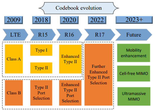
Image Source : A Review of Codebooks for CSI Feedback in 5G New Radio and Beyond
Since the initial launch of LTE in 2009, advancements in multi-antenna technology and increasing performance demands have driven continuous evolution in codebook design. This structured evolution reflects the industry's efforts to balance complexity, performance, and feedback overhead as wireless communication systems advance.
Below is a detailed look at the codebook evolution over time:
LTE (2009): - Class A Codebook:
- Utilized closed-loop feedback.
- Precoding was based on feedback derived from a discrete Fourier transform (DFT) matrix.
- Pilot sequences were not precoded at the base station (BS).
- Class B Codebook:
- Relied on precoded pilots.
- UEs estimated the effective channel based on these precoded pilots.
- Precoder index selection was based on the strongest amplitude from the channel estimation.
5G NR Release 15 (2018): - Type I Codebook:
- Derived from Class A Codebook.
- Emphasized simplicity with moderate spatial resolution.
- Type II Codebook:
- Also evolved from Class A Codebook.
- Provided enhanced spatial resolution, though at the cost of higher feedback overhead.
- Type II Port Selection Codebook:
- Evolved from Class B Codebook.
- Introduced support for multi-beam reporting, improving performance in scenarios involving multiple transmission beams.
5G NR Release 16 (2020): - Enhanced Type II Codebook:
- Supported subband-wise PMI (Precoding Matrix Indicator) calculations.
- Balanced feedback overhead through spatial and frequency domain compression.
- Enhanced Type II Port Selection Codebook:
- Extended the multi-beam reporting capabilities introduced in R15.
- Incorporated optimizations for broader bandwidths and larger antenna arrays.
5G NR Release 17 (2022): - Further Enhanced Type II Port Selection Codebook:
- Improved on the performance of its predecessor using partial reciprocity between uplink (UL) and downlink (DL) channels.
- Targeted scenarios requiring more precise channel state feedback.
5G Advanced and Beyond (2023+): - Envisioned applications of future codebooks include:
- High-mobility transmission support.
- Cell-free MIMO for distributed antenna systems.
- Ultramassive MIMO for extremely high capacity and efficiency.
Types of Codebook
There are two types of Codebook defined in 5G.
- Type I is based on the same logic as LTE codebook. NR Type I codebook is just a little bit more complicated and support more diverse types of matrices. Basically, this type uses a bunch of predefined matrices which is selected by UE report and RRC Configuration. (Ref [33])
- NR Type II is not based on predefined table, it is based on a specifically designed mathemical formula with a lot of parameters. Those parameters in the formula is determined by RRC and UE report. If you look at the Type II codebook, you would not see such a many different tables like Type I codebook. You would see only one table in Type II codebook but you would notice the formula defining the precoding matrix is much more complicated. With those complicated formula and a lot of parameters, Type II can apply more sophisticated precoding matrix than Type I. (Ref [33])
- Type II is based on more detailed CSI report and designed mainly for MU-MIMO (Multi User MIMO)
- Both Type I and Type II codebook are constructed from 2-D DFT based grid of beams and enable the CSI feedback of beam selection as well as PSK based co-phase combining between two polarization. (Ref [34])
- Comparing to Type I (Type I reports defines only the phase of selected beam, not the amplitude), Type II codebook based CSI feedback reports the wideband and subband amplitude information of the selected beams. (Ref [34])
- The difference between Type I and Type II is well illustrated by Ref [38] as shown below. The point is that Type I select only one specific beam from a group of beams, whereas type II select a group of beam and linearly combine all the beams within the group.
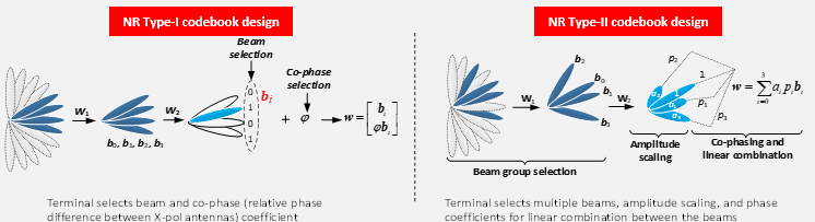
Image Source : 3GPP 5G Technology and Self Evaluation Results
I found a review paper that describe and summarize very well about Type I and Type II codebook : A Review of Codebooks for CSI Feedback in 5G New Radio and Beyond.
Type I Codebook
Type I Codebook is a foundational method for beam selection in 5G. While Single-Panel is straightforward and efficient, Multi-Panel provides more flexibility and better performance in complex environments. Both types play essential roles depending on the network's needs and deployment scenarios. Overall logic of Type I codebook are illustrated below.
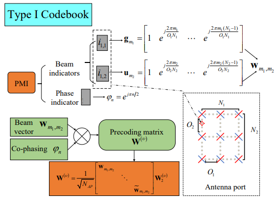
Image Source : A Review of Codebooks for CSI Feedback in 5G New Radio and Beyond.
Followings are summary of the key parameters used in Type I codebook shown in the above diagram.
|
Parameter |
Meaning |
|---|---|
|
I1 |
Horizontal and vertical beam indicators. |
|
i1,1, i1,2 |
Indices for horizontal (m1) and vertical (m2) beams. |
|
I2 |
Phase indicator (φn = ejπn/2). |
|
wm1,m2 |
2D beam vector (frequency-independent). |
|
W(2) |
Co-phasing matrix (frequency-dependent). |
|
N1, N2 |
Antenna grid dimensions (horizontal/vertical). |
|
O1, O2 |
Oversampling factors for the grid. |
|
NAP |
Number of antenna ports. |
-
Setup:
-
This type is used when the base station has a single antenna array (a set of antennas in one group).
-
It works well in situations where signals travel directly (line-of-sight) from the base station to the UE.
-
How it Works:
-
PMI (Precoding Matrix Indicator):
-
The base station sends signals in multiple directions (or beams).
-
The UE selects the best beam based on its signal strength and reports it back to the base station using PMI.
-
Beam and Co-Phasing:
-
The PMI has two parts:
-
Beam Indicator: Chooses the best horizontal and vertical beams for signal transmission.
-
Phase Indicator: Fine-tunes the signal by adjusting its phase (timing).
-
Advantages:
-
Simple and computationally efficient.
-
Works best in environments with minimal signal reflections or obstructions.
-
Limitations:
-
Supports a limited number of "layers" (max 8), meaning it can�t handle many simultaneous data streams.
-
Performance drops in multipath scenarios (when signals bounce off walls or objects).
-
Setup:
-
Used when the base station has multiple groups of antenna arrays (called "panels").
-
This setup is more complex but allows better handling of challenging scenarios like urban areas with lots of obstructions.
-
How it Works:
-
In addition to selecting the best horizontal and vertical beams, the UE now provides additional information:
-
Inter-Panel Co-Phasing: How signals from different panels should be synchronized.
-
Panel Combination: Indicates which panels should be used for transmission.
-
Advantages:
-
Can handle multipath scenarios better than Single-Panel Codebooks.
-
Supports more complex configurations and additional beams for higher data rates.
-
Limitations:
-
More complicated to implement.
-
Requires extra feedback from the UE, increasing overhead.
-
Single-Panel:
-
Simpler, lower overhead.
-
Limited to one antenna array.
-
Best for clear, line-of-sight communication.
-
Multi-Panel:
-
More complex, higher overhead.
-
Uses multiple antenna arrays.
-
Better for environments with obstructions and signal reflections.
Type II Codebook
Type II Codebook is a powerful enhancement over Type I, offering better support for complex environments and multiple beams. It ensures more accurate feedback, enabling advanced features like multi-user MIMO, but at the cost of increased complexity and feedback requirements.
-
Purpose: Introduced in 5G NR Release 15, Type II Codebook improves upon Type I by better supporting multipath channels and enabling multiple beams.
-
Key Difference: It can report up to four beams simultaneously, allowing the system to handle complex wireless environments like urban areas with many reflections and obstructions.
-
Trade-Off: It provides better performance than Type I Codebook but requires more feedback overhead, meaning the UE sends more detailed information back to the base station.
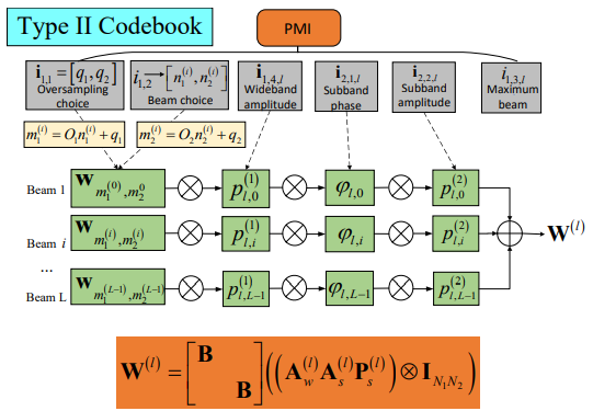
Image Source : A Review of Codebooks for CSI Feedback in 5G New Radio and Beyond.
Followings are summary of the key parameters used in Type II codebook shown in the above diagram.
|
Parameters |
Meaning |
|---|---|
|
i1,1, i1,2 |
Indices for selecting beams in the horizontal (m1) and vertical (m2) directions from the DFT grid. |
|
L |
The number of beams (or layers) selected by the UE. It is determined by i2. |
|
i2 |
Indicator specifying how to choose L beams from the total set of N1N2 beams. |
|
P(1)l,i |
Wideband amplitude of beam l for all subbands. |
|
P(2)l,i |
Subband amplitude of beam l for a specific subband. |
|
cl,i |
Quantized phase information for beam l, represented in NPSK format. |
|
Is |
Binary parameter indicating subband reporting:
|
|
wm1,m2 |
Beam vector representing the selected beam direction (horizontal and vertical). |
|
A(l) |
Wideband diagonal matrix containing beam amplitudes for layer l. |
|
P(l)s |
Diagonal matrix representing subband amplitude for layer l. |
|
W(l) |
Precoding matrix combining beam vectors, amplitudes, and phases for layer l. |
Followings are the highlits of Type II codebook
The Precoding Matrix Indicator (PMI) in Type II Codebook is more detailed than in Type I, as it includes information for:
-
Beam Selection:
i1,1 and i1,2 are indices that select beams from the 2D DFT grid. These determine the horizontal (m1) and vertical (m2) beam directions.
-
Beam Amplitudes:
Includes information about the strength of each beam:
- Wideband amplitude: Pl,i(1), covering the entire frequency band.
- Subband amplitude: Pl,i(2), providing finer details for specific subbands.
-
Phase Information:
Quantized phase values are provided for each beam to ensure alignment. This is expressed as:
ej2πcl,i/NPSK, where NPSK is the number of phase states (e.g., 4 or 8).
-
Wideband and Subband Reporting:
The parameter Is determines whether subband information is included:
- Is = 1: Subband amplitude is reported for each subband.
- Is = 0: Only wideband amplitude is reported.
Wideband amplitude represents the overall strength of the beam across the entire bandwidth, while subband amplitude provides finer granularity by detailing strength in specific frequency ranges.
To reduce feedback overhead, Type II Codebook introduces compression techniques:
- Predominant Beams: Only the strongest beams are reported, reducing the amount of feedback data.
- Quantized Phases: Phase information is compressed using fewer bits.
This compression balances performance and feedback efficiency, especially in systems with large antenna arrays or wide bandwidths.
The precoding matrix W(l) determines how signals are transmitted across beams and antennas. It is a weighted combination of:
- Beam Direction: Represented by wm1,m2, which determines the spatial direction of the beam.
- Wideband Amplitude: A(l), indicating beam strength across the entire bandwidth.
- Subband Amplitude: P(l)s, which provides detailed strength for specific subbands.
- Phase Alignment: Quantized phase values to ensure constructive interference at the receiver.
The matrix is constructed to support multiple beams, making it effective in multipath environments.
- Multi-Beam Support: It can handle multiple signal paths, improving performance in complex environments like urban areas.
- Accurate Feedback: Provides detailed channel state information (CSI), enabling efficient resource allocation and interference cancellation.
- Improved Performance: Particularly useful for multi-user MIMO (MU-MIMO) scenarios.
- Higher Feedback Overhead: More detailed feedback requires the UE to send more data to the base station.
- Implementation Complexity: Managing and processing the additional information is computationally demanding.
In 5G NR Release 16, an Enhanced Type II Codebook was introduced to improve performance and reduce overhead, making it better suited for massive antenna arrays and wider bandwidths.
Enhanced Type II Codebook
The Enhanced Type II Codebook is an upgrade introduced in 5G NR Release 16 to further improve upon the Type II Codebook. It is specifically designed for wideband massive MIMO systems and provides better feedback compression in both spatial and frequency domains.
The Enhanced Type II Codebook is a highly sophisticated method for feedback and precoding in 5G. It offers significant performance improvements, especially for wideband massive MIMO, while addressing the challenges of feedback overhead through innovative compression techniques. However, balancing accuracy and complexity remains a key area for future developments.
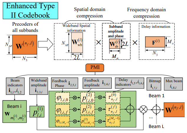
Image Source : A Review of Codebooks for CSI Feedback in 5G New Radio and Beyond.
Followings are summary of the key parameters used in Enhanced Type II codebook shown in the above diagram.
|
Parameters |
Description |
|---|---|
|
i1,1, i1,2 |
Beam indicators used to select horizontal (m1) and vertical (m2) beams from the DFT grid. |
|
i1,5, i1,6 |
Delay indicators for mapping subbands in the angle-delay domain. |
|
i1,7,l |
Bitmap indicator specifying subbands with non-zero coefficients, reducing feedback overhead. |
|
i1,8 |
Indicator for the strongest subband coefficient at layer l, similar to i1,3,l in Type II Codebook. |
|
i2,3,1 |
Wideband amplitude indicator quantized with 4 bits for each polarization direction. |
|
P(1)l,i |
Quantized wideband amplitude for each beam. |
|
P(2)l,i |
Subband amplitude for a specific beam, quantized with 3 bits for higher accuracy. |
|
φl,i,f |
Feedback phase information for subbands, quantized in a 4PSK manner to align beam phases. |
|
W(l)SB |
Subband-specific precoding matrix, incorporating amplitude and phase information. |
|
Mu |
Number of frequency basis vectors used in IDFT compression for subband feedback. |
|
n3,l |
Index of the strongest frequency basis vector at layer l, derived from subband delay information. |
|
τn,l |
Delay domain representation of subband feedback, mapped via IDFT. |
Followings are the highlits of Enhanced Type II codebook
- Better Feedback Reduction: Uses Discrete Fourier Transform (DFT) and Inverse DFT (IDFT) to compress feedback in spatial and frequency domains, significantly reducing feedback size while maintaining performance.
- Increased Beam and Layer Capacity: Supports up to 6 beams and increases the maximum number of layers from 4 to 6.
- Enhanced Subband Reporting: Subband amplitude and phase information are always reported, allowing finer frequency control.
- Spatial Domain: Beams are chosen to characterize the angular structure of the channel, reducing redundant feedback.
- Frequency Domain: Subbands are compressed using delay indicators and IDFT, reporting only critical data points.
The PMI (Precoding Matrix Indicator) in Enhanced Type II Codebook is more detailed and includes:
- Beam Indicators: i1,1 and i1,2, specifying horizontal and vertical beam directions.
- Wideband Amplitude Indicators:
- i2,3,1: Feedback amplitude for beams.
- k(1)l,0, k(1)l,1: Quantized wideband amplitude for each polarization.
- Subband Amplitude: P(2)l,i: 3-bit subband amplitude information.
- Phase Information: Quantized phase values (φl,i,f) using 4PSK for alignment across subbands.
- Bitmap Indicators: i1,7,l: Identifies subbands with non-zero coefficients to reduce feedback size.
Compression reduces feedback size by:
- Focusing on Strongest Beams: Reports only the most significant beams or layers.
- Reducing Coefficients: Ignores weak or negligible subband information.
The precoding matrix W(n,l) integrates spatial and frequency compression:
- Beam Directions: Specified by wm1,m2.
- Wideband Amplitude: Includes polarization-specific blocks for detailed control.
- Subband Amplitude and Phase: Transformed to the angle-delay domain and reconstructed at the base station.
- Better Multi-User MIMO (MU-MIMO) Support: Handles scenarios where multiple users share the same frequency.
- Improved Performance: High gains relative performance improvement compared to older codebooks.
- Reduced Feedback Overhead: Efficient compression reduces the data the UE needs to send.
- Feedback Overhead: Still a challenge in systems with large bandwidths or high antenna counts.
- Complexity: Requires advanced algorithms and high computational resources.
Port Selection Codebook
Port selection codebooks are an efficient way to reduce UE-side complexity while allowing the gNB to flexibly generate beams. This approach is especially beneficial for advanced MIMO systems and non-standard antenna configurations. Further enhancements in Release 17 focus on reducing feedback overhead and improving spectral efficiency.
- Definition: A type of codebook where the UE selects antenna ports instead of directly selecting beams. The base station (gNB) uses this information to determine the optimal beams for data transmission.
- Difference: Unlike non-port selection codebooks, where the UE directly estimates and reports the best beams, port selection codebooks use binary port choices that simplify UE-side complexity.
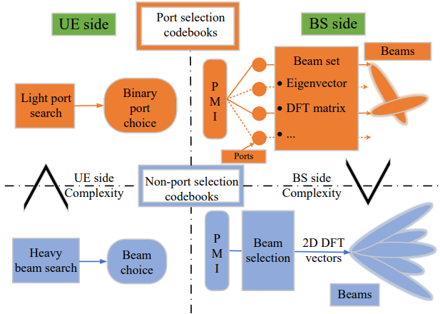
Image Source : A Review of Codebooks for CSI Feedback in 5G New Radio and Beyond.
Followings are the highlits of Port Selection codebook
- UE-Side Simplicity:
The UE reports a port selection decision instead of calculating specific beams. This reduces computational complexity at the UE.
- Beam Selection by gNB:
The gNB determines the beams using the reported port and predefined beamforming matrices (e.g., DFT vectors or eigenvectors of the channel covariance matrix).
- Flexibility:
Port selection supports non-standard antenna arrays and more flexible beamforming strategies. Beams are not limited to the uniform planar array (UPA) or discrete Fourier transform (DFT) grids.
- Reduced UE Complexity: The UE performs simpler port selection instead of heavy beam searching.
- Flexibility in Beam Generation: The gNB can choose beams from diverse antenna configurations, such as eigenvectors or non-DFT-based approaches.
- Type II Port Selection Codebook (R15):
Basic version introduced in Release 15. UE reports beam group selection based on port sampling.
- Enhanced Type II Port Selection Codebook (R16):
Introduced feedback compression for better efficiency. Supports 3-bit quantization for amplitude and phase feedback.
- Further Enhanced Type II Port Selection Codebook (R17):
Utilizes partial reciprocity between uplink (UL) and downlink (DL) to reduce overhead. Supports more beams with enhanced frequency domain compression using IDFT.
- The UE selects ports grouped by a parameter d (port sampling group).
- The gNB maps these ports to beams using:
- DFT matrices.
- Eigenvectors of the channel covariance matrix.
- Beams are reconstructed at the gNB using feedback coefficients provided by the UE.
|
Aspect |
Port Selection Codebook |
Non-Port Selection Codebook |
|---|---|---|
|
Beam Reporting |
UE selects port; gNB determines beams |
UE directly reports beam information |
|
UE Complexity |
Low (simpler binary port selection) |
High (requires heavy beam computation) |
|
Beam Formation |
Flexible (not limited to DFT vectors) |
Assumes DFT vectors for beams |
|
gNB Processing |
Requires intelligent algorithms for beam mapping |
Relatively simpler beam mapping |
- Feedback Overhead: Though reduced at the UE side, port selection still requires efficient gNB-side processing.
- Complex gNB Algorithms: The gNB must determine beams using limited feedback.
Do we(the reciever) have to know the precoding matrix to decode the received signal ?
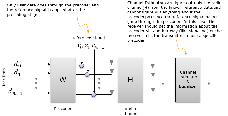
Shall we(the reciever) know the precoding matrix to decode the received signal ? The answer varies depending on how the data transmission scheme is designed. There are roughly two cases of implementation as shown below. In short, the reciever does not need to know of the precoding matrix information in Case 1 and the reciever should know of the precoding matrix in case 2. (See Chapter 11 of Ref [10])
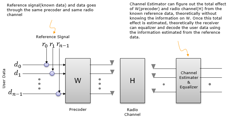
NR implementation belong to < Case 1 >.
Most of LTE transmission Mode (e.g, TM1,2,3,4 etc) belong to < Case 2 >. That is, only data(e.g, PDSCH) is precoded and the reference signal for channel estimation (i.e, Cell Specific Reference Signal) is not precoded. In this case, UE should know of which precoding matrix is applied by eNB. UE knows of this based on predefined specification (as in TM1,2,3) or signaling information delivered by eNB(i.e, PMI index field in DCI).
But even in LTE, TM9 belong to < Case 1 > in which PDSCH carries its own demodulation reference signal. In this case, no precoding matrix is applied at the LTE precoding step. In stead, both PDSCH data and PDSCH DMRS would go through a beamforming process. This beamforming process can be regarded as a kind of precoding. Since both PDSCH data and PDSCH DMRS goes through the same beamforming process, UE does not need to know of the precoding matrix that eNB used.
Then why we care of the precoder (codebook) in NR. 'We don't need to know' doesn't mean 'it is useless'. Even if it is not mandatory, it will be definitely helpful for the reciever if it knows of the codebook.
Looking further into Reference Signal
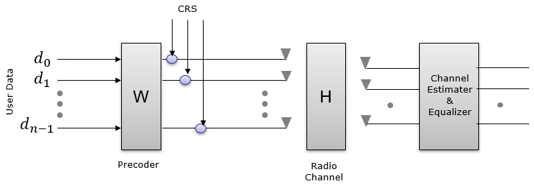
Extending the explanation a little bit further into various possible cases with different type of reference signals, I classified them into following cases. The comments written here is what I had in my mind when I was drawing this diagram and the comments may not be very clear or even misleading if you go into details, but at least it helped me with understanding overal mathematical flow and refernce signal design in this way.
In this case, there is one reference signal called CRS. According to this diagram, the CRS is modified by [H] matrix (Channel Matrix). If we assume that CRS is known to reciever in advance (e.g, by specification), the reciever can use this signal to estimate [H] by comparing the received CRS and the expected CRS (the CRS specified in specification). Then the question is 'can the reciever decode User data(d) only with knowledge of [H] ?'. Highly likely NOT because the user data is modified by not only by [H] but also by [W]. Then next question is 'can the reciever estimate (figure out) [W] ? The reciever cannot know [W] directly from the recieved signal. The information about [W] should be known to the reciever by other means like signaling message or physical control information or predefined specification.
LTE using Cell specific Reference Signal belong to this case.
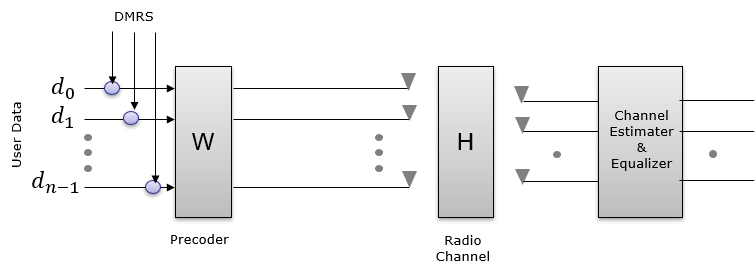
In this case, there is one reference signal called DMRS. According to this diagram, the DMRS is modified by [W](Precoding matrix) and [H] matrix (Channel Matrix). If we assume that DMRS is known to reciever in advance (e.g, by specification), the reciever may be able to decode user data by correcting the received signal with DMRS. But if you ask 'Can UE estimate [W] and [H] ?'. Highly likely No. Reciever can estimate the product of [H][W] by comparing the received DMRS and the expected DMRS, but it would not be possible to estimate [H] and [W] separately.
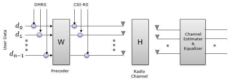
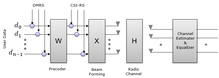
In this case, there is two reference signal called DMRS and CSI-RS. According to this diagram, the DMRS is modified by both [W](Precoding matrix) & [H] matrix (Channel Matrix) and CSI-RS is modified by [H]. The reciever can estimate [H] matrix, but W matrix may not be directly estimated from DMRS since DMRS is modified by both [W] and [H] so [W] information would be given to the reciever by signaling or predefined specification. (Theoretically, if the reciver using both the [H] estimated from CSI-RS and DMRS, it may estimate [W]). In theory, in this case the reciever would be able to decode User Data using DMRS only. If CSI-RS would be helpful additional information, but it would not be critical.
In this case, both DMRS and CSI-RS go through the same process. They are both modified by [X](Beam Forming) & [H] matrix (Channel Matrix). This is the case where PDSCH / DMRS is not precoded.
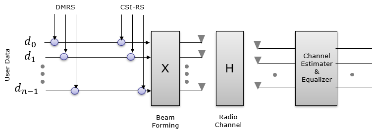
In this case, there is two reference signal called DMRS and CSI-RS. According to this diagram, the DMRS is modified by [W](Precoding matrix), [X](Beam Forming) & [H] matrix (Channel Matrix) and CSI-RS is modified by [X] and [H]. The reciever can estimate [H][X] matrix but [X] and [H] cannot be estimated individually. From DMRS, the reciever can estimate [H][X][W] but they cannot be separated individually. In conclusion, in this case none of the matrix can be estimated individually, but in theory the reciever should be able to decode User Data with DMRS only since the DMRS can undo the effect of all combined matrix [H][X][W].
How can UE or gNB knows about the precoder information ?
In UE's perspective, a typical way is to send measurement report for PMI to gNB and may assume that gNB would use the PMI(Precoding Matrix Indicator) that it reports... but the important thing to remember is ... it is not mandatory for gNB to use the PMI that UE report. It may or may not use the same PMI depending on its own situation. Even if gNB use different PMI than what UE report, UE can decode the downlink data because the downlink data(PDSCH) carries its own reference signal from the beginning as explained in < Case 2 > in previous section. UE can estimate the channel using the DMRS and in many cases this type of channel estimation would be good enough to decode PDSCH.
In gNB's perspective, a typical way is to tell UE to send SRS and pick a specific PMI based the channel estimation of SRS, and tell UE via DCI 0_1 (TMPI field) to use a specific PMI. In this case, UE shall use the specific precoding matrix specified by gNB. If we can assume that UE and gNB is in such a condition where channel reciprocity is guaranteed (like well calibrated TDD channel), gNB can use the channel information from SRS for estimating downlink channel quality and selecting downlink beam.
Where to start ? - Understanding basic terminologies.
The first problem that I got when I start reading the section 38.214-5.2.2.2 was to figure out the meaning of strange looking single character parameters like N1,N2,O1,O2 which is not clearly defined in the TS(Technical Specification) and some other terminology like 'Panel' (as in single panel, multi panel as shown in the RRC message). When some terminolgy is not clearly defined in TS document, it is highly likely that they are described in some TDocs (R1-XXXXX) and transferred to TS document without clear explanation. So I started search TDocs about this topic and I found a TDoc Ref [1],[5],[6],[7],[8] which seems to be the origin of this topic and some other documents as in Ref [2] and Ref [3] that would help us to understand other terminology like 'Panel'.
NOTE : Basically, most of the fundamental concept of NR CSI Codebook design is inherited from LTE Rel 13 FD-MIMO codebook design. You would find a lot of detailed description and diagrams in LTE TDocs. Check in the link in Ref [14] , Ref[15] and take a look into the documents on CSI Coddebook.
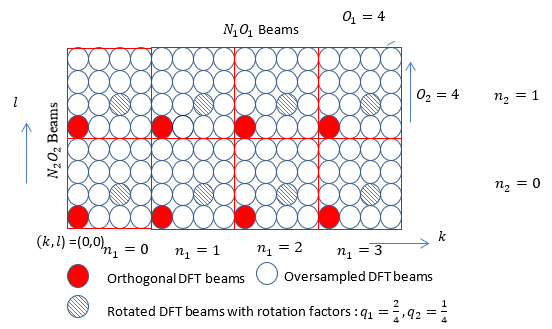
I found a little bit clearer illustration from SamSung Whitepaper shown below, which can associate each of the beam matrix to the angles of vertical and horizontal beam.
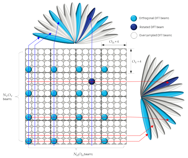
Image Source : Massive MIMO for New Radio (SamSung White Paper)
How can we implement these beams in reality ? The physical implementation would vary. One example of implementation can be illustrated as below.

Image Source : Massive MIMO for New Radio (SamSung White Paper)
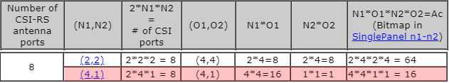
N1, N2, O1, O2 are defined in 3GPP as shown below. I've added some additional column to the table since these additional columns are used often in other parts.
<Type 1 Single Panel : Based on 38.214 v15.3-Table 5.2.2.2.1-2: Supported configurations of (N1,N2) and (O1,O2)>
|
Number of CSI-RS antenna ports |
(N1,N2) |
2*N1*N2 = # of CSI ports |
(O1,O2) |
N1*O1 |
N2*O2 |
N1*O1*N2*O2=Ac (Bitmap in SinglePanel n1-n2) |
|
4 |
2*2*1 = 4 |
(4,1) |
2*4=8 |
1*1=1 |
2*4*1*1 = 8 |
|
|
8 |
2*2*2 = 8 |
(4,4) |
2*4=8 |
2*4=8 |
2*4*2*4 = 64 |
|
|
2*4*1 = 8 |
(4,1) |
4*4=16 |
1*1=1 |
4*4*1*1 = 16 |
||
|
12 |
2*3*2 = 12 |
(4,4) |
3*4=12 |
2*4=8 |
3*4*2*4 = 96 |
|
|
2*6*1 = 12 |
(4,1) |
6*4=24 |
1*1=1 |
6*4*1*1 = 24 |
||
|
16 |
2*4*2 = 16 |
(4,4) |
4*4=16 |
2*4=8 |
4*4*2*4 = 128 |
|
|
2*8*1 = 16 |
(4,1) |
8*4=32 |
1*1=1 |
8*4*1*1 = 32 |
||
|
24 |
2*4*3 = 24 |
(4,4) |
4*4=16 |
3*4=12 |
4*4*3*4 = 192 |
|
|
2*6*2 = 24 |
(4,4) |
6*4=24 |
2*4=8 |
6*4*2*4 = 192 |
||
|
2*12*1 = 24 |
(4,1) |
12*4=48 |
1*1=1 |
12*4*1*1 = 48 |
||
|
32 |
2*4*4 = 32 |
(4,4) |
4*4=16 |
4*4=16 |
4*4*4*4 = 256 |
|
|
2*8*2 = 32 |
(4,4) |
8*4=32 |
2*4=8 |
8*4*2*4 = 256 |
||
|
2*16*1 = 32 |
(4,1) |
16*4=64 |
1*1=1 |
16*4*1*1 = 64 |
<Type 1 Multi Panel : Based on 38.214 v15.3-Table 5.2.2.2.2-1: Supported configurations of (Ng,N1,N2) and (O1,O2)>
|
Number of CSI-RS antenna ports |
(Ng,N1,N2) |
2*Ng*N1*N2 = # of CSI ports |
(O1,O2) |
N1*O1 |
N2*O2 |
N1*O1*N2*O2=Ac (Bitmap in MultiPanel ng-n1-n2) |
|
8 |
2*2*2*1 = 8 |
(4,1) |
2*4=8 |
1*1=1 |
2*4*1*1 = 8 |
|
|
16 |
2*2*4*1 = 16 |
(4,1) |
4*4=16 |
1*1=1 |
4*4*1*1 = 16 |
|
|
2*4*2*1 = 16 |
(4,1) |
2*4=8 |
1*1=1 |
1*4*1*1 = 8 |
||
|
2*2*2*2 = 16 |
(4,4) |
2*4=8 |
2*4=8 |
2*4*2*4 = 64 |
||
|
32 |
2*2*8*1 = 32 |
(4,1) |
8*4=32 |
1*1=1 |
8*4*1*1 = 32 |
|
|
2*4*4*1 = 32 |
(4,1) |
4*4=16 |
1*1=1 |
4*4*1*1 = 16 |
||
|
2*2*4*2 = 32 |
(4,4) |
4*4=16 |
2*4=8 |
4*4*2*4 = 128 |
||
|
2*4*2*2 = 32 |
(4,4) |
2*4=8 |
2*4=8 |
2*4*2*4 = 64 |
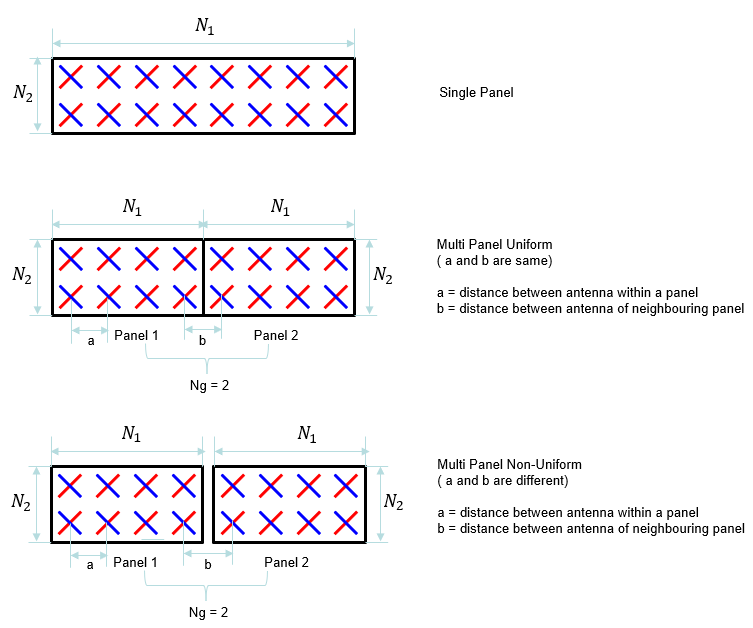
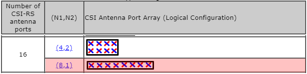
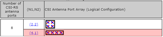
Using this definition, we can visualize the antenna array for each codebook as follows. As you see here, you would notice that there are multiple options of array structure for the same number of CSI-RS antenna ports. Why they propose multiple options ? that is, what is the difference between different options. For example, what would be the difference between 4x1 array and 2x2 array with 8 CSI port ? The main difference caused by this different structure is the shape of the beam in 3D space. For more intuitive understanding, I put another type of my notes in www.slide4math.com. Check out [Array Antenna]
|
Number of CSI-RS antenna ports |
(N1,N2) |
CSI Antenna Port Array (Logical Configuration) |
|
4 |
|
|
|
8 |
|
|
|
|
||
|
12 |
|
|
|
|
||
|
16 |
|
|
|
|
||
|
24 |
 |
|
|
|
||
|
|
||
|
32 |
 |
|
|
|
||
|
|
<Type 1 Multi Panel>
|
Number of CSI-RS antenna ports |
(Ng,N1,N2) |
CSI Antenna Port Array (Logical Configuration) |
|
8 |
|
|
|
16 |
|
|
|
|
||
|
|
||
|
32 |
|
|
|
|
||
|
|
||
Linking TDocs to TS
As mentioned above, it is very diffuclt to understand the specification about CSI-RS codebook just by reading 3GPP TS specification. So in my case I often look into various TDocs and sometimes textbooks about 5G Physical layer. However, in many case it is hard to find direct connection between what TDoc/Textbook says and what 3GPP TS says. In this section, I would put some tips and hints on how to correlate what you usually see from TDoc/Textbook with what 3GPP TS specifies.
The first thing I want to show you is the link shown below. In most TDocs and Textbook, they describe CSI Codebook as W = W1 * W2 (the combination of two matrices) but 3GPP TS does not explicitely describes it in the same way. 3GPP TS just list a whole bunch of tables. The connection between the Codebook in TDoc and 3GPP TS can be illustrated as follows.
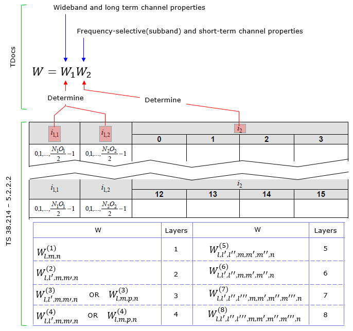
Focusing further into the codebook matrix format, 3GPP TS defines various different form of W matrix depending on the number of layers and some other parameters as shown below.
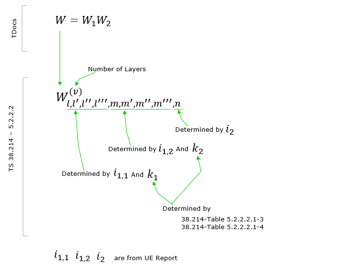
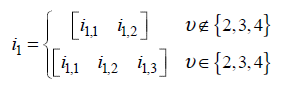
As you may notice from what is mentioned above, there are several parameters labeled as 'i something' like i1_1, i1_2, i_2. According to what I mentioned above, you would figure out that i1_x (i.e, i1_1,i1_2 etc) determines wideband properties and i2 determines subband properies. This relationship specified in 38214-5.2.2.2 as below (In my note, i1_3 is not explicitely described. I would mention on this when I have chance to explain on each specific CSI codebook table in the future. For now, just let you know that i1_3 is an additional parameter that are required to determine the codebook for multi layer).
The construction process of W1 matrix is illustrated as below. As you see, this matrix is associated with antenna structure. Each colum of this matrix represents the weight vector for each specific beam formed by the antenna array. (NOTE : In some documents, the vector X1 ⊗ X2 is described as B, where ⊗ indicate Kronecker Product).
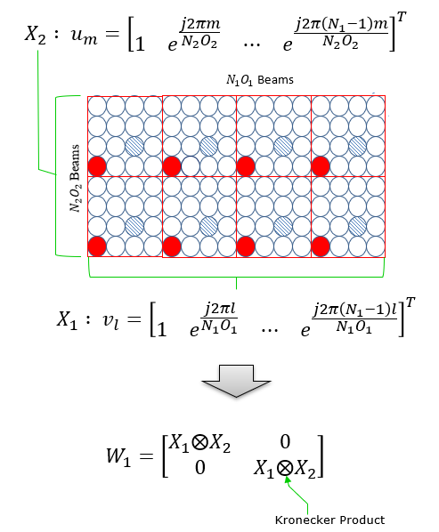
W2 is in the form of vector that functions to select specific beams (columns) of W1.
Even though most of TDocs and Textbook explain about Precoding Matrix using two matrix W1 and W2 , you may not recognize clearly separated matrix in the W matrix given in 3GPP PMI tables. So I would like to give you overall structure of the W matrix given in 3GPP PMI tables. You would see roughly two types of W Matrix structure as below depending on the PMI table you pick.
With this general structure in mind, pick a very simple PMI table that you think you can handle and derive the matrix with pen and pencil as I did in Derivation of W matrix Example. There might be some mistakes that I made in this derivation, but at least it helped me to build much clearer picture on the structure and meaning of the matrix.
Wideband and Subband Report Configuration
As explained in previous section, CSI report in NR is made up of two categories(granularities). One is for Wideband property (Wideband Granularity) and the other one is subband property(subband granularity). These two parameters can be set separately and reported in independent scheduling, which gives more efficiency and flexibility for CSI framework (it may make it difficult for us to understand the mechanism though).
According to 38.214 - 5.2.1.4, Wideband and Subband Report properties can be configured by ReportQuantity in RRC message as follows :
- reportQuantity is set to 'cri-RI-PMI-CQI', or 'cri-RI-LI-PMI-CQI', cqi-FormatIndicator indicates single CQI
- reporting and pmi-FormatIndicator indicates single PMI reporting, or
- reportQuantity is set to 'cri-RI-i1' or
- reportQuantity is set to 'cri-RI-CQI' or 'cri-RI-i1-CQI' and cqi-FormatIndicator indicates single CQI reporting, or
- reportQuantity is set to 'cri-RSRP' or 'ssb-Index-RSRP'
A CSI Reporting Setting is said to have a wideband frequency-granularity if
otherwise, the CSI Reporting Setting is said to have a subband frequency-granularity.
PMI Tables
Followings are summaries on correlations on Type, number of layers, number of CSI antenna ports & dimension and specific mapping table. But it would not be easy to make sense out of this summary table. To understand each of these tables in detail, I would suggest you go through TDocs in reference section (or at least high level descriptions in this note) to get some big picture first and then you need to construct a few specific PMI matrix by hands as I did in example sections.
|
Type |
# of Layers |
Antenna Port |
Codebook Mode |
Pcsi-RS |
N2 |
Ng |
Table in 38.214 |
|
Type I Single-Panel |
1 |
3000~3001 |
|
|
|
|
|
|
2 |
3000~3001 |
|
|
|
|
||
|
1 |
3000~ 2999 + Pcsi-RS |
1 |
|
|
|
||
|
1 |
3000~ 2999 + Pcsi-RS |
2 |
|
> 1 |
|||
|
1 |
3000~ 2999 + Pcsi-RS |
2 |
|
1 |
|||
|
2 |
3000~ 2999 + Pcsi-RS |
1 |
|
|
|||
|
2 |
3000~ 2999 + Pcsi-RS |
2 |
|
> 1 |
|||
|
2 |
3000~ 2999 + Pcsi-RS |
2 |
|
1 |
|||
|
3 |
3000~ 2999 + Pcsi-RS |
1-2 |
< 16 |
|
|
||
|
3 |
3000~ 2999 + Pcsi-RS |
1-2 |
>= 16 |
|
|
||
|
4 |
3000~ 2999 + Pcsi-RS |
1-2 |
< 16 |
|
|
||
|
4 |
3000~ 2999 + Pcsi-RS |
1-2 |
>= 16 |
|
|
||
|
5 |
3000~ 2999 + Pcsi-RS |
1-2 |
|
|
|
Table 5.2.2.2.1-9 |
|
|
6 |
3000~ 2999 + Pcsi-RS |
1-2 |
|
|
|
Table 5.2.2.2.1-10 |
|
|
7 |
3000~ 2999 + Pcsi-RS |
1-2 |
|
|
|
Table 5.2.2.2.1-11 |
|
|
8 |
3000~ 2999 + Pcsi-RS |
1-2 |
|
|
|
Table 5.2.2.2.1-12 |
|
|
Type I Multi Panel |
1 |
3000~ 2999 + Pcsi-RS |
1 |
|
|
{2,4} |
Table 5.2.2.2.2-3 |
|
1 |
3000~ 2999 + Pcsi-RS |
2 |
|
|
2 |
Table 5.2.2.2.2-3 |
|
|
2 |
3000~ 2999 + Pcsi-RS |
1 |
|
|
{2,4} |
Table 5.2.2.2.2-4 |
|
|
2 |
3000~ 2999 + Pcsi-RS |
2 |
|
|
2 |
Table 5.2.2.2.2-4 |
|
|
3 |
3000~ 2999 + Pcsi-RS |
1 |
|
|
{2,4} |
Table 5.2.2.2.2-5 |
|
|
3 |
3000~ 2999 + Pcsi-RS |
2 |
|
|
2 |
Table 5.2.2.2.2-5 |
|
|
4 |
3000~ 2999 + Pcsi-RS |
1 |
|
|
{2,4} |
Table 5.2.2.2.2-6 |
|
|
4 |
3000~ 2999 + Pcsi-RS |
2 |
|
|
2 |
Table 5.2.2.2.2-6 |
|
|
Type II |
1 & 2 |
3000~ 2999 + Pcsi-RS |
|
|
|
|
Table 5.2.2.2.3-5 |
|
Type II Port Selection |
1 & 2 |
3000~ 2999 + Pcsi-RS |
Table 5.2.2.2.4-1 |
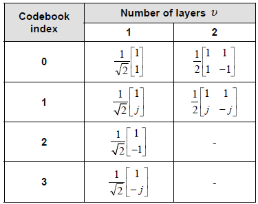
< Table 5.2.2.2.1-1: Codebooks for 1-layer and 2-layer CSI reporting using antenna ports 3000 to 3001 >
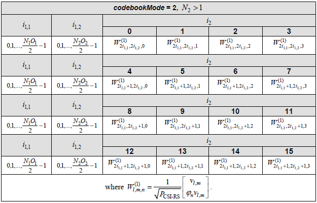
< Table 5.2.2.2.1-5: Codebook for 1-layer CSI reporting using antenna ports 3000 to 2999+P_CSI-RS >

< Table 5.2.2.2.1-6: Codebook for 2-layer CSI reporting using antenna ports 3000 to 2999+P_CSI-RS >
[ Table 5.2.2.2.1-3: Mapping of i1,3 to k1 and k2 for 2-layer CSI reporting ]
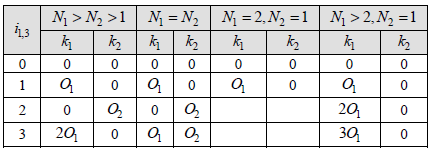
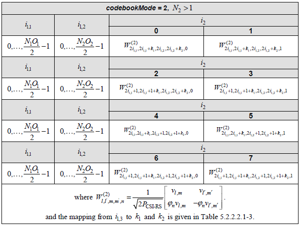
[ Table 5.2.2.2.1-3: Mapping of i1,3 to k1 and k2 for 2-layer CSI reporting ]
[ Table 5.2.2.2.1-3: Mapping of i1,3 to k1 and k2 for 2-layer CSI reporting ]
< Table 5.2.2.2.1-7: Codebook for 3-layer CSI reporting using antenna ports 3000 to 2999+P_CSI-RS >
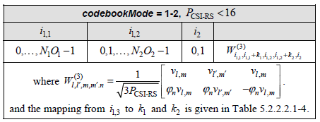
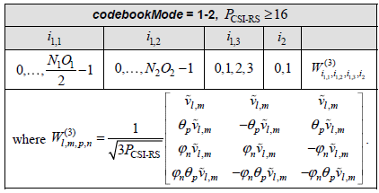
< Table 5.2.2.2.1-4: Mapping of i1,3 to k1 and k2 for 3-layer and 4-layer CSI reporting when P_CSI-RS < 16 >
< Table 5.2.2.2.1-8: Codebook for 4-layer CSI reporting using antenna ports 3000 to 2999+P_CSI-RS >
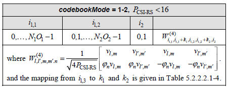
< Table 5.2.2.2.1-4: Mapping of i1,3 to k1 and k2 for 3-layer and 4-layer CSI reporting when P_CSI-RS < 16 >
Derivation of W1 and W2
As briefly mentioned above, W matrix is originally designed to represent the product of two matrix, W1 and W2 (For the original design, refer to Ref [1] and Ref[13]). But it was difficult for me to grasp the practical idea on the concept of the design and had no idea what each of the matrix represents when I first read about an year ago, and then was able to get a little bit of idea when I found a blog (Ref [11]), but not the full picture yet and almost completely forgot about this concept for several month until one of the note reader Daniel(HyungJong) Noh brough up this issue. I still haven't got clear picture about this and Daniel managed to figure out how W1 and W2 can derived quicker quicker than I did and he shared an example showing the derivation of the two matrix and kindly allowed me to share it with readers.
Before going into the example shared by HyungJong, let me give you some additional note to help you (myself as well) to follow through the thought process.
First, I assume that everybody now knows W is defined as follows.
![]()
Based on Ref [1],[11],[13] and 34.214, we can expand this equation as follows. I think W1 would make sense for you now, but the meaning of W2 would still be in mystery from this definition. You will see more concrete form of W2 in the example from HyungJong below. (NOTE : ⊗ indicate Kronecker Product).

Now let's follow through the example from HyungJong. In this example, we assume the following case (Same as in W matrix calculation Example 01, but i1,1, i1,2, i2 are not spefified (i.e, remain as generic variable)
No of CSI ports = 4
N1 = 2, N2 = 1, O1 = 4, O2 = 1
Let's start with Calculating B. B can be calculated as follows based on the definition that is explained in Linking TDoc to TS section.

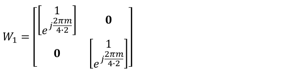
Based on this, you can construct W1 matrix as follows.
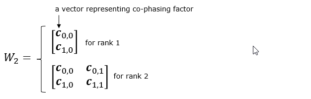
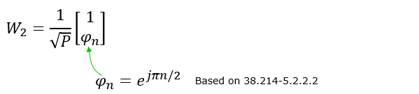
From the condition given to this example, you can define W2 matrix as follows. You may refer to Ref [11] and the seciton 6.12.4.2.1 of Ref[32] for further details on W2 definition.
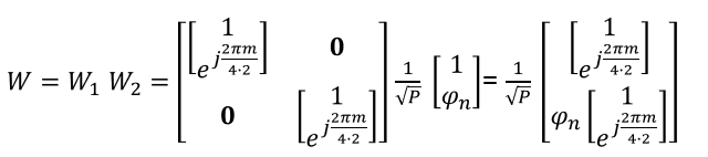
With the W1 and W2, you can calculate W matrix as follows.
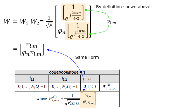
If you modify this W matrix in a little bit different way based on the definition shown at the beginning of this section, you can rewrite this result as follows and you may realize it is the same form described in the table in 38.214 and can understand how the formular in the table is designed.
Derivation of W matrix Examples
In this section, the final matrix you will derive will be in the form of complex number elements. The user data (i.e, PDSCH data) is also in the form of complex number (I and Q data). Eventually you should be able to visualize the properties of these matrix in your brain to make sense out of those matrix. Here goes another type of my notes that may help you with the intuitive understandings on the matrix with complex number elements being applied to complex data. Play with [Matrix Complex]
Example 01 > p4, 1 Layer , N1 = 2, N2 = 1, O1 = 4, O2 = 1, i1,1 = 0 i1,2 = 0 i2 = 0
Let's assume that PMI table is configured according to following table(Table 5.2.2.2.1-5).
Suppose we have following report and antenna configuration as follows :
No of CSI ports = 4
N1 = 2, N2 = 1, O1 = 4, O2 = 1
i1,1 = 0 i1,2 = 0 i2 = 0. This indicates l = i1,1 = 0, m = i1,2 = 0 , n = i2 = 0
Now, let's plug these parameters into all the equations that lead to final matrix. I hope I did all the steps right. Let me know if you find anything wrong.
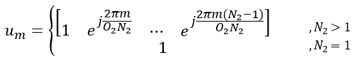
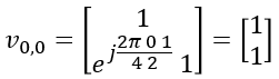
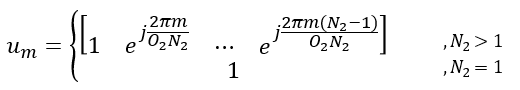
First, figure out um vector.
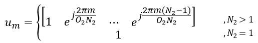
In this example, N2 is 1. So um becomes as follows.
![]()
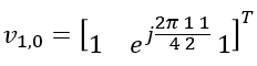
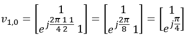
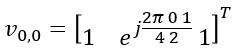
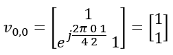
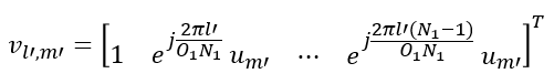
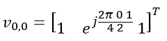
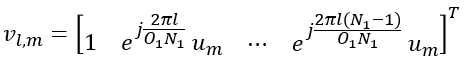
Next, figure out vl,m vector.
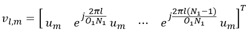
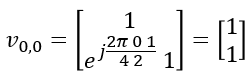
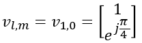
In this example, l = 0, m = 0. so vl,m become as follows :
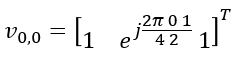
Transposing the vector, we get following vector
Now calculaing Phi value using the parameter n.
![]()
Plugging into n value given in this example, we get the value as follows.
![]()
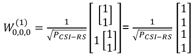
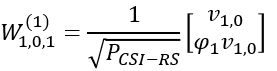
Now plugging into the matrix all the vectors we got above
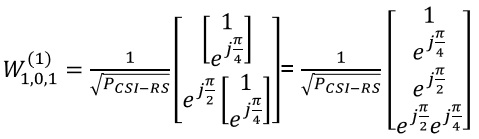
Plugging l,m,n value given in this example, we get following vector
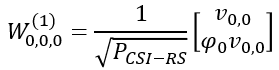
Do all the calculation to the end, we get the final matrix(vector) as follows.
Example 02 p4, 1 Layer , N1 = 2, N2 = 1, O1 = 4, O2 = 1, i1,1 = 1 i1,2 = 0 i2 = 1
Let's assume that PMI table is configured according to following table (Table 5.2.2.2.1-5).
Suppose we have following report and antenna configuration as follows :
No of CSI ports = 4
N1 = 2, N2 = 1, O1 = 4, O2 = 1
i1,1 = 1 i1,2 = 0 i2 = 1. This indicates l = i1,1 = 1, m = i1,2 = 0 , n = i2 = 1
Now, let's plug these parameters into all the equations that lead to final matrix. I hope I did all the steps right. Let me know if you find anything wrong.
First, figure out um vector.
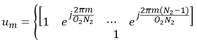
In this example, N2 is 1. So um becomes as follows.
![]()
Next, figure out vl,m vector.
In this example, l = 0, m = 0. so vl,m become as follows :
Transposing the vector, we get following vector
Now calculaing Phi value using the parameter n.
![]()
Plugging into n value given in this example, we get the value as follows.
![]()
Now plugging into the matrix all the vectors we got above

Plugging l,m,n value given in this example, we get following vector
Do all the calculation to the end, we get the final matrix(vector) as follows.
Example 03> p4, 2 Layer , N1 = 2, N2 = 1, O1 = 4, O2 = 1, i1,1 = 0 i1,2 = 0 i2= 0, i1,3 = 0
Let's assume that PMI table is configured according to following table ( Table 5.2.2.2.1-6 ).
Suppose we have following report and antenna configuration as follows :
No of CSI ports = 4
N1 = 2, N2 = 1, O1 = 4, O2 = 1
i1,1 = 0, i1,2 = 0, i1,3 = 0, i2= 0.
This indicates
k1 = 0, k2 = 0
l = i1,1 = 0, l= i1,1+k1=0, m = i1,2 = 0, m = i1,2+k2 = 0, n = i2 = 0
Let's figure out um vector first.
Since N2 = 1 in the given condition in this example, um become 1
![]()
Now let's derive vl,m vector
Since both l and m is 0 in this example, the vector become as follows.
Transposing the vector and simplifing it, we get
Calculating Phi with n given in this example, we get the phi value as follows.
![]()
![]()
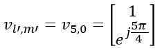
In the same as we did for vl,m, we can calculate vl',m' from following equation.
Plugging the number for l' and m', we get following
Transposing and Simplifying, we get
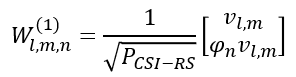
Now let's plug into the final matrix all the vectors and values that we derived above.
Rewriting the matrix by plugging in parameters (l,l',m,m',n), it looks as follows.
Then, plugging the vectors and values derived above into the matrix, we get the final result as follows.
Example 04> p4, 2 Layer , N1 = 2, N2 = 1, O1 = 4, O2 = 1, i1,1 = 0 i1,2 = 0 i2= 1, i1,3 = 1
Let's assume that PMI table is configured according to following table.
Suppose we have following report and antenna configuration as follows :
No of CSI ports = 4
N1 = 2, N2 = 1, O1 = 4, O2 = 1
i1,1 = 1, i1,2 = 0, i1,3 = 1, i2= 1.
This indicates
k1 = O1=4, k2 =0 [Note : Since this is the case where N1 > N2 > 1, k1 becomes O1 and k2 becomes 0 when i1,3 = 1]
l = i1,1 = 1, l= i1,1+k1=1+4=5, m = i1,2 = 0, m = i1,2+k2 = 0+0 = 0, n = i2 = 1
Let's figure out um vector first.
Since N2 = 1 in the given condition in this example, um become 1
![]()
Now let's derive vl,m vector
Since both l is 1 and m is 0 in this example, the vector become as follows.

Transposing the vector and simplifing it, we get
Calculating Phi with n given in this example, we get the phi value as follows.
![]()
![]()
Now let's derive vl',m' from the following vector.
Plugging l' and m' into the equation, we get a vector as follows.

Trransposing and Symplifying the vector, we get
Now let's derive the final matrix from following equation.
Plugging the vectors and parameters we got in previous step , we get following
Plugging the number and simplifying, we get the final result as follows :
Example 05> p16, 1 Layer , N1 = 8, N2 = 1, O1 = 4, O2 = 1
Let's assume that we want to figure out the codebook for following configuration. (NOTE : I put the graphical representation of all the possible codebooks in this example in my visual note in 4 pages : here, here, here, here. Check if you can correlate the mathmatical representation shown here and the graphical representation).

Assuming that codebookmode = 2, the codebook table we have to apply is following (Table 5.2.2.2.1-5 )
Let's figure out um vector first.
Since N2 = 1 in the given condition in this example, um become 1
![]()
Now let's derive vl,m vector
Since N1 is 8 in this example, we would get a huge vector as shown below. (In this example, I haven't specified any specific i_x value. I will leave it as a variable)

Plugging this reslut into the codebook matrix format of Table 5.2.2.2.1-5 and map the result to the logical antenna configuration, it can be illustrated as follow.

Example 06> p8, 4 Layer , N1 = 4, N2 = 1, O1 = 4, O2 = 1
Let's assume that we want to figure out the codebook for following configuration
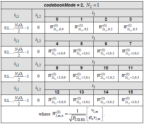
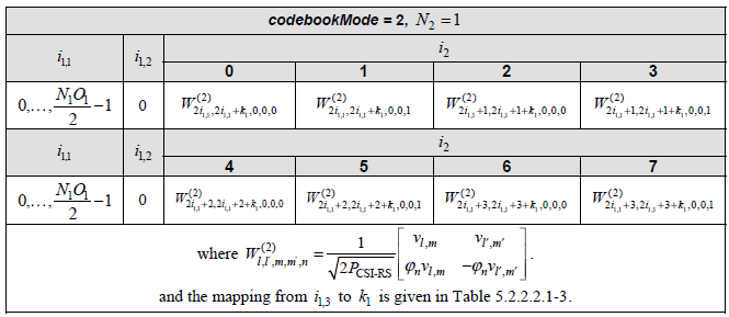
Assuming that codebookmode = 2, the codebook table we have to apply is following (Table 5.2.2.2.1-7 )
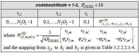
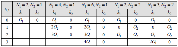
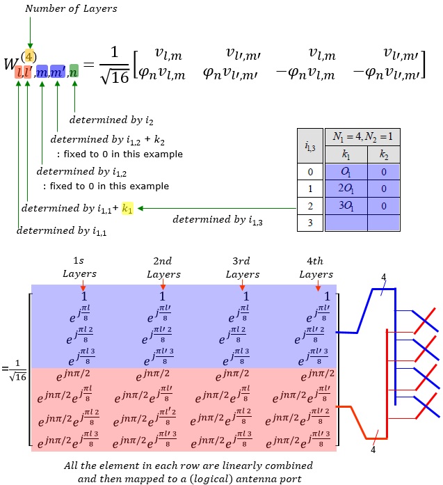
You would notice that there are other variable k1, k2 is required to derive this codebook matrix. Those k1, k2 values are defined in the following table(Table 5.2.2.2.1-4).
Let's figure out um vector first.
Since N2 = 1 in the given condition in this example, um become 1
![]()
Now let's derive vl,m vector
Since N1 is 4 in this example, we would get a vector as shown below. (In this example, I haven't specified any specific i_x value. I will leave it as a variable)

Plugging this reslut into the codebook matrix format of Table 5.2.2.2.1-7 and map the result to the logical antenna configuration, it can be illustrated as follow.
Base Formula for Type II Codebook
Codebook Type II is not using any predefined PMI matrix. In stead, it is generating a beam forming equation based on various information in UE measurement report. To do this, there should a formula (a mathematical template) known both on UE and Network. The detailed equation described in 38.214 may look too complicated to many people including me.
I was trying to find a little bit simplified form of the formula for me to get the basic concept more easily/clearly and following is one of the equation that I found in Ref[34] Amplitude Quantization for Type-2 Codebook Based CSI Feedback in New Radio System. This paper is about codebook type II, not the Enhanced Codebook Type II but I think the basic concept is same.
The overall form of beam forming matrix is as follows. W matrix is made up of Wr,l where r indicates polarization and l indicates layers. The final structure of the matrix is similar to what is shown in Linking TDoc to TS section. The difference lies in how each of the matrix elements is calculated.
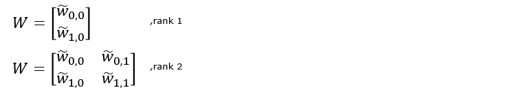
Now let's take a look at how each of the matrix elements look like. As shown below, the codebook type II is made up of multiple codebook type I formula and amplitude scaler which are linearly combined.
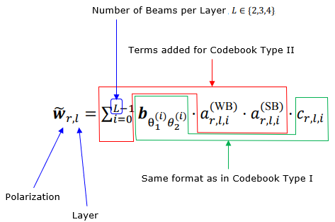
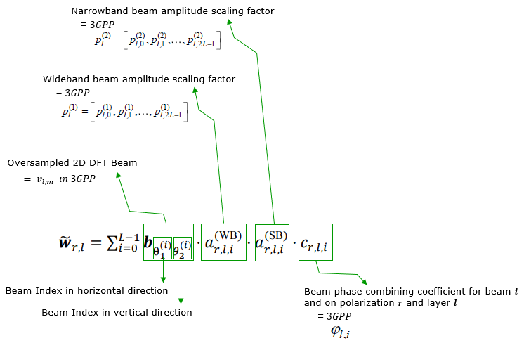
Each components of the equation can be further described as below.
Type II Codebook
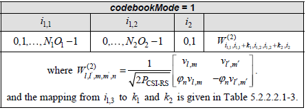
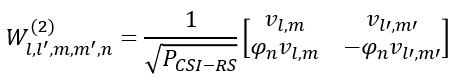
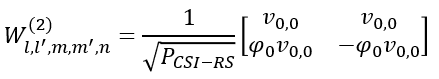
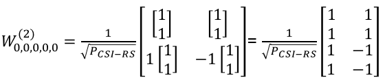
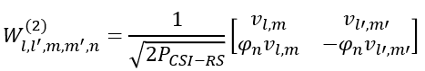
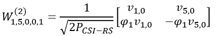
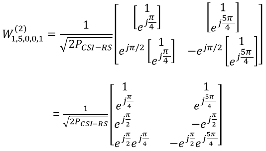
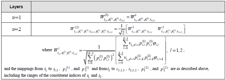
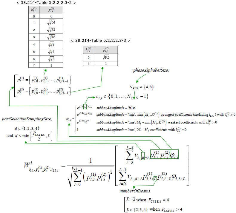
< 38.214-Table 5.2.2.2.3-5: Codebook for 1-layer and 2-layer CSI reporting using antenna ports 3000 to 2999+P_CSI-RS >
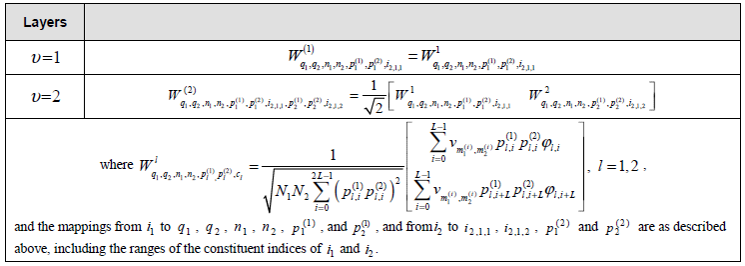
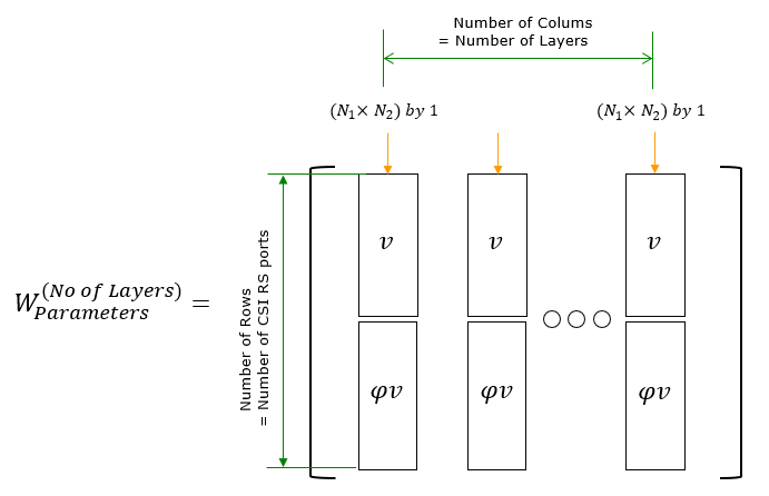
The overall structure of the W matrix is as follows. 'v' term is the one generate the base form of beam forming matrix and the logic of this term is basically as in codebook type I. Refer to Derivation of W matrix Examples section for the details. 'p' term is amplitude scaling factors and 'Phi' term is Phase combining coefficient between polarization 0 and polarization 1.
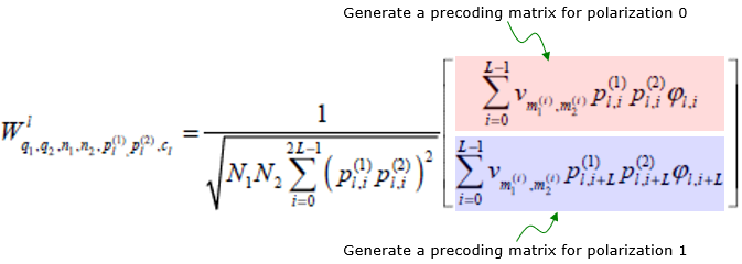
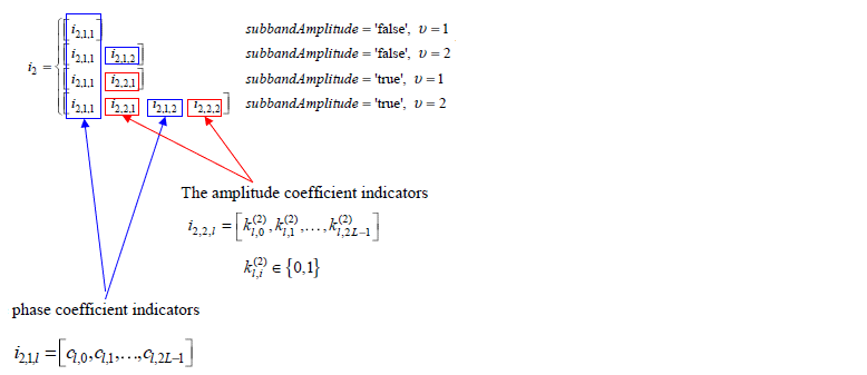
Now let's take a look into the details of each parameters used in the formula.

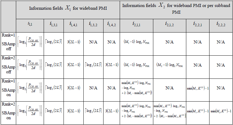
Now the question is how each of the parameter in the formula is determined. Those parameters are determined by the CSI measurement report from UE as summarized below.
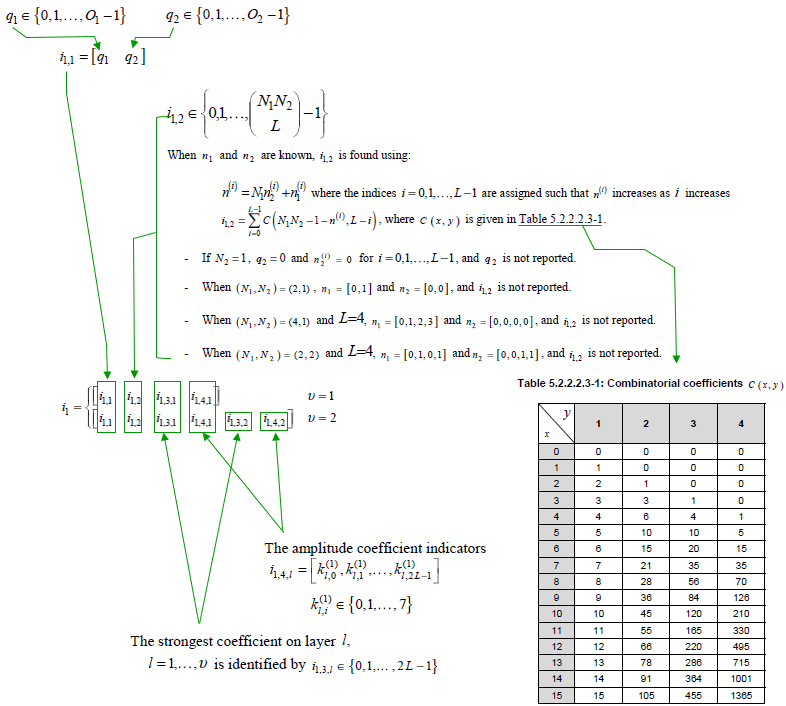
< 38.212-Table 6.3.2.1.2-1: PMI of codebookType= typeII >

Type II Port Selection Codebook
< 38.214-Table 5.2.2.2.4-1: Codebook for 1-layer and 2-layer CSI reporting using antenna ports 3000 to 2999+P_CSI-RS >
< 38.212-Table 6.3.2.1.2-2: PMI of codebookType= typeII-PortSelection >
Enhanced Type II Codebook
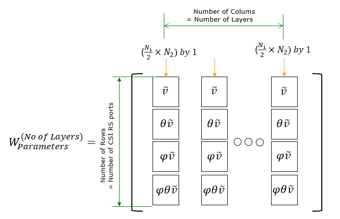
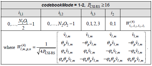
<38.214-Table 5.2.2.2.5-5: Codebook for 1-layer. 2-layer, 3-layer and 4-layer CSI reporting using antenna ports
3000 to 2999+PCSI-RS>
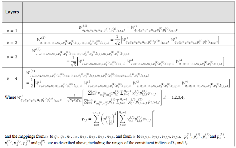
< 38.214-Table 5.2.2.2.5-1 >

For enhanced codebood type II, UE should report a huge set of information as summarized as below.
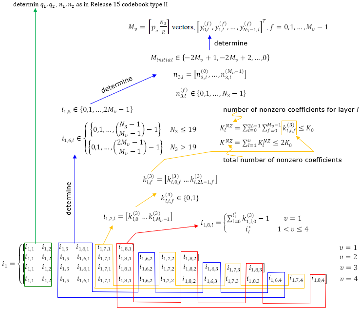
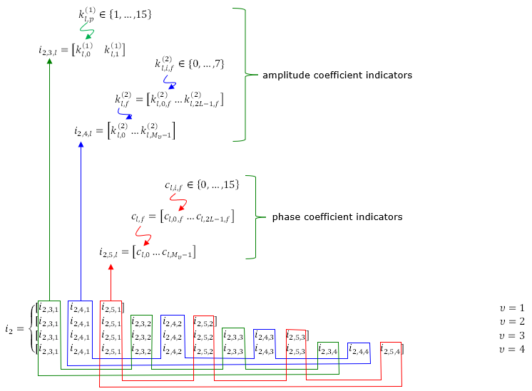
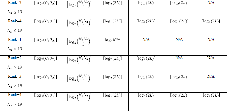
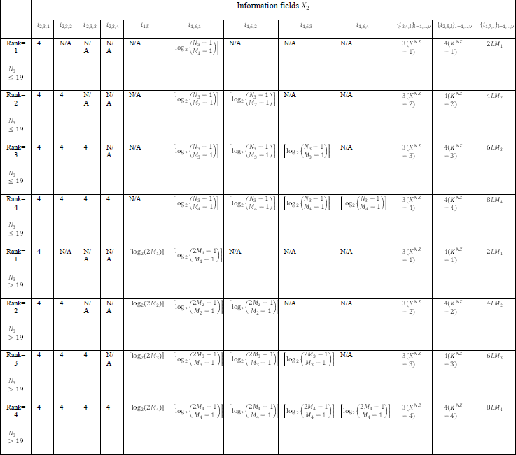
< 38.212-Table 6.3.2.1.2-1A: PMI of codebookType= typeII-r16 >

Putting All these together
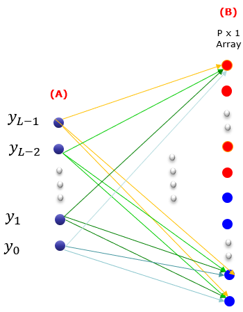
As I mentioned, it is very challenging to understand the detailed mechanism of CSR-RS in terms of each separate component (like CSI-RS signal generation, Codebook Configuration, related RRC parameters), but still some overall flow that put all these together has been mystery to me for a long time.
Just recently with a lot of TDoc reading and a critical help from one of the active readers of my notes, I think I reached much closer to the understandings on the overall process.
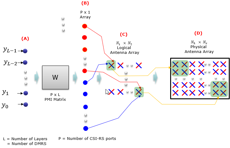
Followings short notes for each process.
Does UE knows all these detailed mapping information ?
In short, UE knows the details of (A) -> (B) -> (C) via DCI and RRC configuration, but it doesn't know anything about (D). But this technology is designed in such a way that UE does not need to know about (D). We say this as '(C) -> (D) mapping is transparent to UE'.
How to interpret RRC parameters and i values ?
This section describes about RRC parameters for the codebook only but the codebook parameter is associated with CSI RS parameters. For the details of CSI-RS parameters, refer to CSI-RS page.
I will also discuss about UE measurement parameters related to the codebook based CSI report in this section.
< Type I-Single Panel >
For a while, we may stay with type I-SinglePanel. So for now, I would describe only on the codebook setting in RRC for type I Single pannel case.
type1 SEQUENCE {
subType CHOICE {
typeI-SinglePanel SEQUENCE {
nrOfAntennaPorts CHOICE {
two SEQUENCE {
twoTX-CodebookSubsetRestriction BIT STRING (SIZE (6))
},
moreThanTwo SEQUENCE {
n1-n2 CHOICE {
two-one-TypeI-SinglePanel-Restriction BIT STRING (SIZE (8)),
two-two-TypeI-SinglePanel-Restriction BIT STRING (SIZE (64)),
four-one-TypeI-SinglePanel-Restriction BIT STRING (SIZE (16)),
three-two-TypeI-SinglePanel-Restriction BIT STRING (SIZE (96)),
six-one-TypeI-SinglePanel-Restriction BIT STRING (SIZE (24)),
four-two-TypeI-SinglePanel-Restriction BIT STRING (SIZE (128)),
eight-one-TypeI-SinglePanel-Restriction BIT STRING (SIZE (32)),
four-three-TypeI-SinglePanel-Restriction BIT STRING (SIZE (192)),
six-two-TypeI-SinglePanel-Restriction BIT STRING (SIZE (192)),
twelve-one-TypeI-SinglePanel-Restriction BIT STRING (SIZE (48)),
four-four-TypeI-SinglePanel-Restriction BIT STRING (SIZE (256)),
eight-two-TypeI-SinglePanel-Restriction BIT STRING (SIZE (256)),
sixteen-one-TypeI-SinglePanel-Restriction BIT STRING (SIZE (64))
},
typeI-SinglePanel-codebookSubsetRestriction-i2 BIT STRING (SIZE (16))
}
},
typeI-SinglePanel-ri-Restriction BIT STRING (SIZE (8))
},
Even though this is RRC message, you would not get much detailed information from 38.331 (RRC Specification). You should see 38.214 in order to find the detailed information on this part. For typeI-SinglePanel case, refer to 38.214-5.2.2.2.1. Followings are some important statement.
|
Number of Antenna Port |
Port Numbers |
|
4 |
3000~3003 |
|
8 |
3000~3007 |
|
12 |
3000~3011 |
|
16 |
3000~3015 |
|
24 |
3000~3023 |
|
32 |
3000~3031 |
|
Number of Layers |
i parameters |
|
1,5,6,7,8 |
i1,1 , i1,2 , i2 |
|
2,3,4 |
i1,1 , i1,2 , i1,3 , i2 |
< Type II >
type2 SEQUENCE {
subType CHOICE {
typeII SEQUENCE {
n1-n2-codebookSubsetRestriction CHOICE {
two-one BIT STRING (SIZE (16)),
two-two BIT STRING (SIZE (43)),
four-one BIT STRING (SIZE (32)),
three-two BIT STRING (SIZE (59)),
six-one BIT STRING (SIZE (48)),
four-two BIT STRING (SIZE (75)),
eight-one BIT STRING (SIZE (64)),
four-three BIT STRING (SIZE (107)),
six-two BIT STRING (SIZE (107)),
twelve-one BIT STRING (SIZE (96)),
four-four BIT STRING (SIZE (139)),
eight-two BIT STRING (SIZE (139)),
sixteen-one BIT STRING (SIZE (128))
},
typeII-RI-Restriction BIT STRING (SIZE (2))
},
typeII-PortSelection SEQUENCE {
portSelectionSamplingSize ENUMERATED {n1, n2, n3, n4} OPTIONAL,
typeII-PortSelectionRI-Restriction BIT STRING (SIZE (2))
}
},
phaseAlphabetSize ENUMERATED {n4, n8},
subbandAmplitude BOOLEAN,
numberOfBeams ENUMERATED {two, three, four}
}
As per 38.214-5.2.2.2.3, Followings are some important statement.
|
Number of Antenna Port |
Port Numbers |
|
4 |
3000~3003 |
|
8 |
3000~3007 |
|
12 |
3000~3011 |
|
16 |
3000~3015 |
|
24 |
3000~3023 |
|
32 |
3000~3031 |
< Enhanced Type II >
CodebookConfig-r16 ::= SEQUENCE {
codebookType CHOICE {
type2 SEQUENCE {
subType CHOICE {
typeII-r16 SEQUENCE {
n1-n2-codebookSubsetRestriction-r16 CHOICE {
two-one BIT STRING (SIZE (16)),
two-two BIT STRING (SIZE (43)),
four-one BIT STRING (SIZE (32)),
three-two BIT STRING (SIZE (59)),
six-one BIT STRING (SIZE (48)),
four-two BIT STRING (SIZE (75)),
eight-one BIT STRING (SIZE (64)),
four-three BIT STRING (SIZE (107)),
six-two BIT STRING (SIZE (107)),
twelve-one BIT STRING (SIZE (96)),
four-four BIT STRING (SIZE (139)),
eight-two BIT STRING (SIZE (139)),
sixteen-one BIT STRING (SIZE (128))
},
typeII-RI-Restriction-r16 BIT STRING (SIZE(4))
},
typeII-PortSelection-r16 SEQUENCE {
portSelectionSamplingSize-r16 ENUMERATED {n1, n2, n3, n4},
typeII-PortSelectionRI-Restriction-r16 BIT STRING (SIZE (4))
}
},
numberOfPMI-SubbandsPerCQI-Subband-r16 INTEGER (1..2),
paramCombination-r16 INTEGER (1..8)
}
}
}
As per 38.214-5.2.2.2.3, Followings are some important statement.
|
Number of Antenna Port |
Port Numbers |
|
4 |
3000~3003 |
|
8 |
3000~3007 |
|
12 |
3000~3011 |
|
16 |
3000~3015 |
|
24 |
3000~3023 |
|
32 |
3000~3031 |
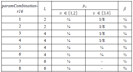
< 38.214 - Table 5.2.2.2.5-1: Codebook parameter configurations for L, β and pv >

The UE is not expected to be configured with paramCombination-r16 equal to
3,4,5,6,7 or 8 when Pcsi-rs = 4
7 or 8 when Pcsi-rs < 32
7 or 8 when higher layer parameter typeII-RI-Restriction-r16 is configured with ri=1 for any i > 1
7 or 8 when R = 2
The parameter R is configured with the higher-layer parameter numberOfPMI-SubbandsPerCQI-Subband. This parameter controls the total number of precoding matrices N3 indicated by the PMI as a function of the number of configured subbands in csi-ReportingBand
RRC Parameters for CSI RS
PortIndexFor8Ranks ::= CHOICE {
portIndex8 SEQUENCE{
rank1-8 PortIndex8 OPTIONAL, -- Need R
rank2-8 SEQUENCE(SIZE(2)) OF PortIndex8 OPTIONAL, -- Need R
rank3-8 SEQUENCE(SIZE(3)) OF PortIndex8 OPTIONAL, -- Need R
rank4-8 SEQUENCE(SIZE(4)) OF PortIndex8 OPTIONAL, -- Need R
rank5-8 SEQUENCE(SIZE(5)) OF PortIndex8 OPTIONAL, -- Need R
rank6-8 SEQUENCE(SIZE(6)) OF PortIndex8 OPTIONAL, -- Need R
rank7-8 SEQUENCE(SIZE(7)) OF PortIndex8 OPTIONAL, -- Need R
rank8-8 SEQUENCE(SIZE(8)) OF PortIndex8 OPTIONAL -- Need R
},
portIndex4 SEQUENCE{
rank1-4 PortIndex4 OPTIONAL, -- Need R
rank2-4 SEQUENCE(SIZE(2)) OF PortIndex4 OPTIONAL, -- Need R
rank3-4 SEQUENCE(SIZE(3)) OF PortIndex4 OPTIONAL, -- Need R
rank4-4 SEQUENCE(SIZE(4)) OF PortIndex4 OPTIONAL -- Need R
},
portIndex2 SEQUENCE{
rank1-2 PortIndex2 OPTIONAL, -- Need R
rank2-2 SEQUENCE(SIZE(2)) OF PortIndex2 OPTIONAL -- Need R
},
portIndex1 NULL
}
CodebookConfig ::= SEQUENCE {
codebookType CHOICE {
type1 SEQUENCE {
subType CHOICE {
typeI-SinglePanel SEQUENCE {
nrOfAntennaPorts CHOICE {
two SEQUENCE {
twoTX-CodebookSubsetRestriction BIT STRING (SIZE (6))
},
moreThanTwo SEQUENCE {
two-one-TypeI-SinglePanel-Restriction BIT STRING (SIZE (8)),
two-two-TypeI-SinglePanel-Restriction BIT STRING (SIZE (64)),
four-one-TypeI-SinglePanel-Restriction BIT STRING (SIZE (16)),
three-two-TypeI-SinglePanel-Restriction BIT STRING (SIZE (96)),
six-one-TypeI-SinglePanel-Restriction BIT STRING (SIZE (24)),
four-two-TypeI-SinglePanel-Restriction BIT STRING (SIZE (128)),
eight-one-TypeI-SinglePanel-Restriction BIT STRING (SIZE (32)),
four-three-TypeI-SinglePanel-Restriction BIT STRING (SIZE (192)),
six-two-TypeI-SinglePanel-Restriction BIT STRING (SIZE (192)),
twelve-one-TypeI-SinglePanel-Restriction BIT STRING (SIZE (48)),
four-four-TypeI-SinglePanel-Restriction BIT STRING (SIZE (256)),
eight-two-TypeI-SinglePanel-Restriction BIT STRING (SIZE (256)),
sixteen-one-TypeI-SinglePanel-Restriction BIT STRING (SIZE (64))
},
typeI-SinglePanel-codebookSubsetRestriction-i2 BIT STRING (SIZE (16))
}
},
typeI-SinglePanel-ri-Restriction BIT STRING (SIZE (8))
},
typeI-MultiPanel SEQUENCE {
two-two-one-TypeI-MultiPanel-Restriction BIT STRING (SIZE (8)),
two-four-one-TypeI-MultiPanel-Restriction BIT STRING (SIZE (16)),
four-two-one-TypeI-MultiPanel-Restriction BIT STRING (SIZE (8)),
two-two-two-TypeI-MultiPanel-Restriction BIT STRING (SIZE (64)),
two-eight-one-TypeI-MultiPanel-Restriction BIT STRING (SIZE (32)),
four-four-one-TypeI-MultiPanel-Restriction BIT STRING (SIZE (16)),
two-four-two-TypeI-MultiPanel-Restriction BIT STRING (SIZE (128)),
four-two-two-TypeI-MultiPanel-Restriction BIT STRING (SIZE (64))
},
ri-Restriction BIT STRING (SIZE (4))
}
},
codebookMode INTEGER (1..2)
},
type2 SEQUENCE {
subType CHOICE {
typeII SEQUENCE {
n1-n2-codebookSubsetRestriction CHOICE {
two-one BIT STRING (SIZE (16)),
two-two BIT STRING (SIZE (43)),
four-one BIT STRING (SIZE (32)),
three-two BIT STRING (SIZE (59)),
six-one BIT STRING (SIZE (48)),
four-two BIT STRING (SIZE (75)),
eight-one BIT STRING (SIZE (64)),
four-three BIT STRING (SIZE (107)),
six-two BIT STRING (SIZE (107)),
twelve-one BIT STRING (SIZE (96)),
four-four BIT STRING (SIZE (139)),
eight-two BIT STRING (SIZE (139)),
sixteen-one BIT STRING (SIZE (128))
},
typeII-RI-Restriction BIT STRING (SIZE (2))
},
typeII-PortSelection SEQUENCE {
portSelectionSamplingSize ENUMERATED {n1, n2, n3, n4} OPTIONAL,
typeII-PortSelectionRI-Restriction BIT STRING (SIZE (2))
}
},
phaseAlphabetSize ENUMERATED {n4, n8},
subbandAmplitude BOOLEAN,
numberOfBeams ENUMERATED {two, three, four}
}
}
}
CodebookConfig-r16 ::= SEQUENCE {
codebookType CHOICE {
type2 SEQUENCE {
subType CHOICE {
typeII-r16 SEQUENCE {
n1-n2-codebookSubsetRestriction-r16 CHOICE {
two-one BIT STRING (SIZE (16)),
two-two BIT STRING (SIZE (43)),
four-one BIT STRING (SIZE (32)),
three-two BIT STRING (SIZE (59)),
six-one BIT STRING (SIZE (48)),
four-two BIT STRING (SIZE (75)),
eight-one BIT STRING (SIZE (64)),
four-three BIT STRING (SIZE (107)),
six-two BIT STRING (SIZE (107)),
twelve-one BIT STRING (SIZE (96)),
four-four BIT STRING (SIZE (139)),
eight-two BIT STRING (SIZE (139)),
sixteen-one BIT STRING (SIZE (128))
},
typeII-RI-Restriction-r16 BIT STRING (SIZE(4))
},
typeII-PortSelection-r16 SEQUENCE {
portSelectionSamplingSize-r16 ENUMERATED {n1, n2, n3, n4},
typeII-PortSelectionRI-Restriction-r16 BIT STRING (SIZE (4))
}
},
numberOfPMI-SubbandsPerCQI-Subband-r16 INTEGER (1..2),
paramCombination-r16 INTEGER (1..8)
}
}
}
Reference
[1] 3GPP TSG-RAN WG1 #87 R1-1612661 : Advanced CSI Codebook Structure
[3] 5G New Radio (NR) : Physical Layer Overview and Performance : IEEE Communication Theory Workshop - 2018
[4] A Tutorial on Beam Management for 3GPP NR at mmWave Frequencies
[5] 3GPP TSG-RAN WG1 #86 R1-166579 : Discussion on codebook design to support up to 32 ports CSI RS
[6] 3GPP TSG-RAN WG1 #86 R1-167140 : Codebook for up to 32 ports CSI-RS
[7] 3GPP TSG-RAN WG1 #86 R1-166342 : Codebook Design for Class A CSI Reporting up to 32 Ports
[8] 3GPP TSG-RAN WG1 #86 R1-166445 : Codebook design for {20, 24, 28, 32} ports
[9] Advanced antenna systems for 5G networks
[10] 5G NR (THE NEXT GENERATION WIRELESS ACCESS TECHNOLOGY) - Erik Dahlman, Stefan Parkvall, Johan Skold
[11] Analyze 5G NR Type I SP Codebook
[12] 3GPP TSG-RAN WG1 #90 R1-171nnnn [DRAFT] Summary on views on CSI reporting for Type I and Type II
[13] 3GPP TSG RAN WG1 Meeting #82b R1-155490 Rank 1-2 codebook for Class A CSI reporting
[14] RAN1#82-BIS (2015-10-05 - Malmo(SE)) : TDocs
[15] 3GPP TDocs (written contributions) at meeting : R1-85 - 2016-05-23 to 2016-05-27, Nanjing
[16] 3GPP TSG RAN WG1 Meeting #85 : R1-164776 View on class A codebook extension
[17] 3GPP TSG RAN WG1 Meeting #85 : R1-164777 Hybrid PMI codebook based CSI reporting and simulation results
[18] 3GPP TSG RAN WG1 Meeting #85 : R1-164780 Linear combination (LC) codebook based CSI reporting and simulation results
[19] 3GPP TSG RAN WG1 Meeting #85 : R1-164857 Discussion on codebook design to support up to 32 ports CSI-RS
[20] 3GPP TSG-RAN WG1#85 : R1-165097 Class A Codebook Design for up to 32 Ports in Rel-14
[21] 3GPP TDocs (written contributions) at meeting : R1-83 - 2015-11-15 to 2015-11-22, Anaheim
[22] 3GPP TSG RAN WG1 Meeting #83 : R1-156790 Rank 2 codebook -- summary of RAN1 proposals and performance
[23] 3GPP TSG RAN WG1 Meeting #83 : R1-156791 Rank 3-8 codebook -- summary of RAN1 proposals and performance
[24] 3GPP TSG RAN WG1 Meeting #83 : R1-156831 Codebook design for Class B
[25] 3GPP TSG RAN WG1 Meeting #83 : R1-157003 16 port codebook design and evaluations
[26] 3GPP TSG RAN WG1 Meeting #83 : R1-157164 Codebook design for elevation BF and FD-MIMO
[27] 3GPP TSG-RAN WG1#83 : R1-157208 Class A Codebook Design for Rank 1-2
[28] 3GPP TSG-RAN WG1#83 : R1-157209 Class A Codebook Design for Rank 3-8
[29] 3GPP TSG RAN WG1 Meeting #83 : R1-157300 Codebook Design for rank 2 for 2D antenna arrays
[30] 3GPP TSG RAN WG1 Meeting #83 : R1-157301 Codebook Design for rank 3 to 8 for 2D antenna arrays
[31] 3GPP TSG RAN WG1 Meeting #83 : R1-157427 Samsung, Ericsson, NTT DOCOMO, CATT
[32] 5G Technology -3GPP New Radio Edited by Harri Holma, Antti Toskala, Takehiro Nakamura
[33] Codebook Based Multi-User MIMO for 5G - Lund University
[34] Amplitude Quantization for Type-2 Codebook Based CSI Feedback in New Radio System
[35] 3GPP TSG-RAN WG1 #89 : R1-1709232 WF on Type I and II CSI codebooks
[36] Massive MIMO for New Radio (SamSung Technical White Paper)
[37] Beamforming - How does it work (Ericsson)
[38] 3GPP Workshop : 3GPP 5G Technology and Self Evaluation Results (Wu Yong)
[39] Overhead Reduction of NR type II CSI for NR Release 16 (Nokia)
[40] Massive MIMO for New Radio (SamSung White Paper)
[41] 5G NR in BULLETS - 13.6.3 PRECODING MATRIX INDICATOR
[42] A Review of Codebooks for CSI Feedback in 5G New Radio and Beyond - arXiv (2023)
YouTube
- A Detailed Introduction to Beamforming - 5G Learning (2018)
- An Introduction to 3D Beamforming - 5G Learning (2019)
- What Are Phased Arrays? - Matlab (2022)
- An introduction to Beamforming - Matlab (2022)
- Why multichannel beamforming is useful for wireless communication - Matlab (2023)
- Multi-User MIMO Beamforming in 5G New Radio - Matlab (2023)