Data between UE and Network (or another UE) go through various components on the data path. In most case, the resource allocation and the data path is configured statically or semi-statically. We cannot say all those components are optimized for each individual user or each individual use case (e.g, rush time traffic, regular hour traffic, eMBB, IoT etc). However, in ideal case where you can configure resource allocation and parameters of the components along the data path dynamically (by automation), we may define a set of parameters of all the components on the data path in most optimal way for specific UEs or specific use cases. The specific set of parameters assigned for the UEs or use cases is called a 'Slice' of the network. Network Slice is a logical concept of splitting all the resources along the data path into multiple sets, each of which is optimized for specific UEs or use cases.

Followings are the list of the topics we want to look into
- Implementation Requirement
- Slicing vs 5QI(QoS) vs DNN(APN)
- Network Slicing vs Private Network
- Signaling for Network Slicing
- Who decides which slide to use ?
- Identification of Network Slice
- So many different types of NSSAIs
- Get the Test Procedure and Log / Amarisoft TechAcademy
Implementation Requirement
I don't think there is any specification which explicitely defines all the details on how to implement these slices. But by the nature of dynamic configuration changes, we would easily guess that all the network elements along the data path should be constructed in such a way to change the configuration by remote control and automation. That's why the concept of network slicing can easily be achievable in 5G where most of the network components are designed for virtualization and the components along the transport (e.g, routers) is designed as SDN (Software Defined Network).
Slicing vs 5QI(QoS) vs DNN(APN)
Since Network Slicing is a concept of configuraing all the component along the end to end communication path, it can do everything that QoS(5QI in case of NR) and DNN(APN). That is, a certain aspect of network slicing and QoS and API overlaps. Due to this, we are often confused with these three concepts.
In short, I would say Network Slicing would be a superset of QoS and APN. That is, Network Slicing can do everything that QoS and APN do, but not in vice versa, meaning that there are certain aspect of Network Slicing that cannot be done by QoS or APN.
- Streaming video: A streaming video service requires a high data rate and low latency to deliver high-quality video content. In this case, QoS can be used to prioritize video traffic and allocate more network resources to ensure a smooth and uninterrupted viewing experience for users. Network slicing, on the other hand, can be used to create a separate slice for the video service, with customized QoS parameters and resource allocation, ensuring that the video service has the necessary resources to deliver high-quality video content.
- VoNR : QoS and network slicing are both used to support VoNR services in 5G networks, but they serve different purposes. QoS is used to define and enforce specific performance requirements for VoNR traffic, such as low latency and low packet loss. This is critical for ensuring that VoNR services provide a high-quality user experience. Network slicing, on the other hand, can be used to create separate slices for different VoNR services with customized QoS parameters and resource allocation. This enables the network to provide differentiated voice services that are tailored to meet the specific needs of different users and applications. For example, a network slice can be created for emergency services with high priority and guaranteed resources, ensuring that emergency voice calls are always delivered with the highest quality and reliability.
- Industrial automation: Industrial automation requires ultra-low latency and high reliability to support real-time control of machines and systems. QoS can be used to provide the required level of performance and service for industrial automation traffic, but it may not be sufficient to guarantee the necessary level of reliability. In this case, network slicing can be used to create a separate slice for industrial automation, with customized QoS parameters, resource allocation, and security policies, ensuring that the industrial automation traffic has the necessary level of reliability and security.
- Autonomous vehicles: Autonomous vehicles require low latency and high bandwidth to support real-time communication and decision-making. QoS can be used to allocate more network resources to the autonomous vehicle traffic, but it may not be sufficient to provide the necessary level of performance and service. In this case, network slicing can be used to create a separate slice for the autonomous vehicle service, with customized QoS parameters and resource allocation, ensuring that the autonomous vehicle traffic has the necessary level of performance and service.
But there are still some of the network slicing feature that cannot be done by QoS. For example, both Network Slicing and QoS can differentiate SLA between different application type (e.g, SLA between VoNR and eMBB), but QoS cannot differentiate the SLA within the same application. For example, QoS cannot differentiate the SLA between one UE (subscriber, also called a tenant) for the same application (e.g, VoNR) whereas Network Slicing can do.
Network Slicing vs Private Network
As you may notice from previous sections, there are many different ways of slicing the network. Let's suppose the Opeartor Y sliced network as illustrated below. In this example, we see a slice (i.e, dedicated network) for BMW group and FIAT group. From the point of BMW group and FIAT, it would be as if they have their own private network. That is, Network Slicing can be used as a way of implementing Private Network in wider sense of meaning. You may not say this cannot be a private network since the Operator Y would use licensed spectrum. I also agree that a keyword for Private Network was 'Unlicensed Spectrum', but in many case the meaning of technical terms varies (expands in most case) and I think the meaning of Private Network also has evolved to encompass various use case like this. I think this type of Private Network would attract attention not only from private company but also from Network Operators. To be hones, I don't think the private network based on Unlicensed Spectrum would be a strong motivation to existing operators, but this type of private network would be attactive to the established network operators as well.
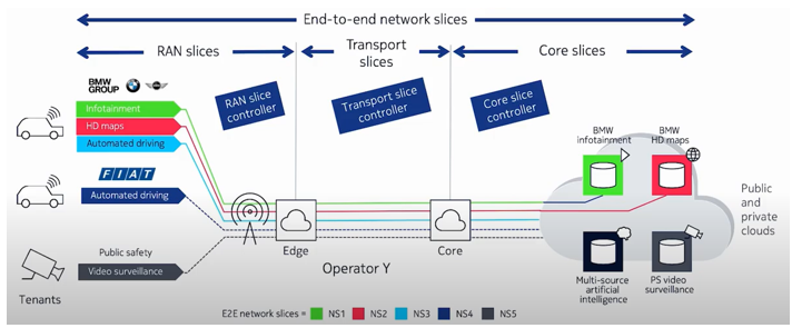
Source : 5G network slicing: automation, assurance and optimization of 5G transport slices
Signaling for Network Slicing
Network slicing signaling process happenes at a few different stages like Initial Attach, PDU Establishment, Policy Change. Probably the most important step would be the process at Initial Attach. PDU Establishment would be mostly for defining various QoS Flow and Polich Change would be to associate the specific slices to a specific UE/Application as specified in the Policy Rules.
Following is the brief signaling flow at initial attach related to network slicing.
- When UE send Registration Request it specifies NSSAI. 3GPP defines a few large group of slice service/type as described here. By this NSSAI in Registration Request message UE tells Network saying that I want to get access to this and this type of slice.
- Then this requested Slice Information is tranferred to UDM. UDM check if the requested slice is allowed for the specific UE. If it is allowed, the UDP accept the request. If not, it rejects the request.
- Once the slice request is accepted, (with a few more steps of checkups on core network side) the acceptance is notified to UE with a few additional information like Configured NSSI, NSSI Inclusion Mode etc.
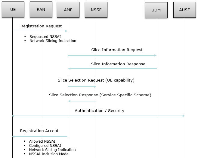
Source : Recreated from MAS5G: Move Around Smartly in 5G (IEEE)
Followings are the IE (Information Elements) involved in the signaling shown above.
- Registration Request.Network Slicing Indication
- Registration Accept.Allowed NSSAI
- Registration Accept.Network Slicing Indication
- Registration Accept.NSSI inclusion mode
The procedure explained above is just about the request and accept process for a specific slice. It does not really create any data pipe (slice). Setting up the real data pipe and associating the pipe with a slice happens at later step using the following procedure.
|
Step |
Direction |
Message |
Type of NSSAI |
|
1 |
UE -> NW |
||
|
2 |
UE <- NW |
||
|
3 |
UE -> NW |
||
|
4 |
UE <- NW |
||
|
5 |
UE <- NW |
Manage UE Policy Command |
Refer to this note |
|
6 |
UE -> NW |
Manage UE Policy Complete |
|
Who decides which slide to use ?
Of course, the final decision is done by network since network functions as a master in almost every communication, but the network slice selection can be triggered by either UE or Network or Both. It depends on a variety of factors such as the type of service or application, the location and capabilities of the mobile phone, and the network conditions.
The mobile phone will typically have a UICC that stores the credentials of the slice it is authorized to use. When the phone connects to the network, it will use the credentials to authenticate with the network and request access to a specific slice.
The network can also decide which slice to assign to the mobile phone based on the type of service or application the phone is trying to access. For example, if the phone is trying to access a high-bandwidth video streaming service, the network may assign it to a slice that has a higher capacity for handling video traffic.
Additionally, Network can also use the mobile phone's location, device capabilities, and other information to decide which slice to assign to it. For example, if the mobile phone is located in an area with a high density of users, the network may assign it to a slice with a lower capacity to ensure fair usage of resources.
This signaling procedure can be illustrated in other way as well illustrated by Rahim Navael as shown below. Rahim kindly approved me to share the illustration in my note.
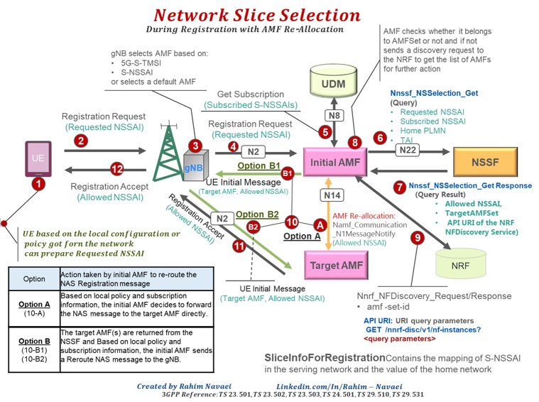
Image Source : Rahim Navaei's linked in post
High level description of the Network Slice selection process can be described as follows. The details are specified in 3GPP 23.501-5.15.5.2.1
- The UE initiates registration with the 5G network by sending a Registration Request message to the 5G Core Network (5GC).
- The Registration Request message includes a list of requested NSSAIs that the UE wants to use for the current registration.
- The 5GC receives the Registration Request message and checks the requested NSSAIs against the allowed NSSAIs configured for the 5G network slice.
- If the requested NSSAIs are allowed by the network, the 5GC selects a network slice based on the configured NSSAIs and sends a Registration Accept message to the UE.
- The Registration Accept message includes the allowed NSSAI and other information necessary for the UE to access the network slice.
- The UE receives the Registration Accept message.
- The 5GC keeps track of the configured NSSAI for each network slice in its database. When a UE initiates a registration, the 5GC uses this information to select the appropriate network slice based on the requested NSSAI.
- When UE want to establish a data session, it specifies a selected NSSAI in UL NAS Transport during PDU session establishement procedure. --> You may not specifies the selected NSSAI at this step, network would assign a default NSSAI as the selected NSSAI.
- If Network can use the selected NSSAI from UE, it would send PDU session establishment accept message with S-NSSAI which indicates the Selected NSSAI.
As illustrated above, most of the important configuration of Network Slice is done in core network side, meaning you need to get the detailed understanding on Signaling for the related corenetwork interface. You may refer to followings notes for corenetwork details.
Identification of Network Slice
The identification of a Network Slice is indicated by a NAS Information Element called S-NSSAI(Single Network Slice Selection Assistance Information) as structured as below. S-NSSAI is made up of two field SST (Slice/Service Type) and SD (Service Differentiator). SD is an optional field. SST has 8 bit field length implying that it can indicates a total of 255 different slice types.
The SST field may have standardized and non-standardized values. Values 0 to 127 belong to the standardized SST
range. Values 128 to 255 belong to the Operator-specific range.
< 23.003 - Figure 28.4.2-1: Structure of S-NSSAI >
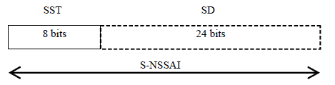
- SST indicates Slice Service Type which is a mandatory item.
- SD indicates a kind of slice ID within the SST which is an option item. This is used to indicates a specific slices in case where there are one or more slices are supported in the same SST.
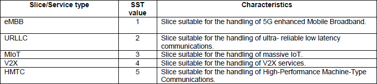
The SST standardized in 3GPP as of now are as shown. Only 5 (as of 23.501 version 17.5.0) out of 127 possible types that can be configured by SST field.
< 23.501 v17.5 - Table 5.15.2.2-1 - Standardised SST values >
So many different types of NSSAIs
When I am reading specification and other documents about network slicing, I was so confused by the variaties of NSSAIs mentioned in those document. I am trying to list those different types of NSSAIs here to clean my understanding and hopely to help other readers.
Protocol discriminator = 0x7e (5GS Mobility Management)
Security header = 0x1 (Integrity protected)
Auth code = 0xc2653407
Sequence number = 0x09
Protocol discriminator = 0x7e (5GS Mobility Management)
Security header = 0x0 (Plain 5GS NAS message, not security protected)
Message type = 0x41 (
5GS registration type:
Follow-on request bit = 1
Value = 1 (initial registration)
ngKSI:
TSC = 0
NAS key set identifier = 2
5GS mobile identity:
5G-GUTI
MCC = 001
MNC = 01
AMF Region ID = 128
AMF Set ID = 4
AMF Pointer = 1
5G-TMSI = 0x2fedc8c7
UE security capability:
0xf0 (5G-EA0=1, 128-5G-EA1=1, 128-5G-EA2=1, 128-5G-EA3=1, 5G-EA4=0, 5G-EA5=0, 5G-EA6=0, 5G-EA7=0)
0x70 (5G-IA0=0, 128-5G-IA1=1, 128-5G-IA2=1, 128-5G-IA3=1, 5G-IA4=0, 5G-IA5=0, 5G-IA6=0, 5G-IA7=0)
0xf0 (EEA0=1, 128-EEA1=1, 128-EEA2=1, 128-EEA3=1, EEA4=0, EEA5=0, EEA6=0, EEA7=0)
0x70 (EIA0=0, 128-EIA1=1, 128-EIA2=1, 128-EIA3=1, EIA4=0, EIA5=0, EIA6=0, EIA7=0)
NAS message container:
Protocol discriminator = 0x7e (5GS Mobility Management)
Security header = 0x0 (Plain 5GS NAS message, not security protected)
Message type = 0x41 (Registration request)
5GS registration type:
Follow-on request bit = 1
Value = 1 (initial registration)
ngKSI:
TSC = 0
NAS key set identifier = 2
5GS mobile identity:
5G-GUTI
MCC = 001
MNC = 01
AMF Region ID = 128
AMF Set ID = 4
AMF Pointer = 1
5G-TMSI = 0x2fedc8c7
5GMM capability:
0x03 (SGC=0, 5G-IPHC-CP CIoT=0, N3 data=0, 5G-CP CIoT=0, RestrictEC=0, LPP=0, HO attach=1, S1 mode=1)
UE security capability:
0xf0 (5G-EA0=1, 128-5G-EA1=1, 128-5G-EA2=1, 128-5G-EA3=1, 5G-EA4=0, 5G-EA5=0, 5G-EA6=0, 5G-EA7=0)
0x70 (5G-IA0=0, 128-5G-IA1=1, 128-5G-IA2=1, 128-5G-IA3=1, 5G-IA4=0, 5G-IA5=0, 5G-IA6=0, 5G-IA7=0)
0xf0 (EEA0=1, 128-EEA1=1, 128-EEA2=1, 128-EEA3=1, EEA4=0, EEA5=0, EEA6=0, EEA7=0)
0x70 (EIA0=0, 128-EIA1=1, 128-EIA2=1, 128-EIA3=1, EIA4=0, EIA5=0, EIA6=0, EIA7=0)
Last visited registered TAI:
MCC = 001
MNC = 01
TAC = 0x000064
S1 UE network capability:
0xf0 (EEA0=1, 128-EEA1=1, 128-EEA2=1, 128-EEA3=1, EEA4=0, EEA5=0, EEA6=0, EEA7=0)
0x70 (EIA0=0, 128-EIA1=1, 128-EIA2=1, 128-EIA3=1, EIA4=0, EIA5=0, EIA6=0, EIA7=0)
0xc0 (UEA0=1, UEA1=1, UEA2=0, UEA3=0, UEA4=0, UEA5=0, UEA6=0, UEA7=0)
0x40 (UCS2=0, UIA1=1, UIA2=0, UIA3=0, UIA4=0, UIA5=0, UIA6=0, UIA7=0)
0x19 (ProSe-dd=0, ProSe=0, H.245-ASH=0, ACC-CSFB=1, LPP=1, LCS=0, 1xSRVCC=0, NF=1)
0x80 (ePCO=1, HC-CP CIoT=0, ERw/oPDN=0, S1-U data=0, UP CIoT=0, CP CIoT=0, ProSe-relay=0, ProSe-dc=0)
0xb0 (15 bearers=1, SGC=0, N1mode=1, DCNR=1, CP backoff=0, RestrictEC=0, V2X PC5=0, multipleDRB=0)
UE's usage setting = 0x01 (Data centric)
LADN indication:
Length = 0
Data =
Network slicing indication = 0x00 (DCNI=0, NSSCI=0)
5GS update type = 0x01 (EPS-PNB-CIoT=no additional information, 5GS-PNB-CIoT=no additional information, NG-RAN-RCU=0, SMS requested=1)
- When providing a Requested NSSAI to the network upon registration, the UE in a given PLMN only includes and uses S-NSSAIs applying to this PLMN.
- The mapping of S-NSSAIs of the Requested NSSAI to HPLMN S-NSSAIs may also be provided (see 23.501-5.15.4.1.2 for when this is needed).
- The S-NSSAIs in the Requested NSSAI are part of the Configured and/or Allowed NSSAIs applicable for this PLMN, when they are available
- If the UE has received NSSRG information together with the Configured NSSAI, it only includes in the Requested NSSAI S-NSSAIs that all share a common NSSRG.
- If no Configured NSSAI and Allowed NSSAI for the PLMN are available, the S-NSSAIs in the Requested NSSAI correspond to the Default Configured NSSAI, if configured in the UE.
- S-NSSAIs that the UE provides in the Requested NSSAI which are neither in the Allowed NSSAI nor provided as a rejected S-NSSAI, shall, by the UE, not be regarded as rejected, i.e. the UE may request to register these S-NSSAIs again next time the UE sends a Requested NSSAI.
UE sends Requested NSSAI in following case. so if the case is in none of these, UE would not include the requested NSSAI.
- the UE has a configured NSSAI for the current PLMN (configured NSSAI is sent by the network in registration accept)
- or the UE has an allowed NSSAI for the current PLMN (allowed NSSAI is sent by the network in registration accept)
- or the UE has neither allowed NSSAI for the current PLMN nor configured NSSAI for the current PLMN and has a
- default configured NSSAI. default configured NSSAI is defined in the configuration of the UE in "default_nssai".
Protocol discriminator = 0x7e (5GS Mobility Management)
Security header = 0x2 (Integrity protected and ciphered)
Auth code = 0x59b0464b
Sequence number = 0x02
Protocol discriminator = 0x7e (5GS Mobility Management)
Security header = 0x0 (Plain 5GS NAS message, not security protected)
Message type = 0x42 (
5GS registration result = 0x09 (Emergency registered=0, NSSAA to be performed=0, SMS allowed=1, 3GPP access)
5G-GUTI:
5G-GUTI
MCC = 001
MNC = 01
AMF Region ID = 128
AMF Set ID = 4
AMF Pointer = 1
5G-TMSI = 0x4b63aa9a
TAI list:
Length = 7
Data = 00 00 f1 10 00 00 64
5GS network feature support:
0x03 (MPSI=0, IWK N26=0, EMF=not supported, EMC=not supported, IMS-VoPS-N3GPP=1, IMS-VoPS-3GPP=1)
0x00 (5G-UP CIoT=0, 5G-IPHC-CP CIoT=0, N3 data=0, 5G-CP CIoT=0, RestrictEC=both CE mode A and CE mode B are not restricted, MCSI=0, EMCN3=0)
T3512 value:
Value = 30
Unit = 5 (1 minute)
Emergency number list:
Length = 8
Data = 03 1f 19 f1 03 1f 11 f2
- The Allowed NSSAI received in a Registration Accept message or a UE Configuration Update Command applies to a PLMN when at least a TAI of this PLMN is included in the RA/TAI list included in this Registration Accept message or UE Configuration Update Command
- If the UE Configuration Update Command contains an Allowed NSSAI but not a TAI List, then the last received RA/TAI list applies for the decision on which PLMN(s) the Allowed NSSAI is applicable.
- If received, the Allowed NSSAI for a PLMN and Access Type and any associated mapping of this Allowed NSSAI to HPLMN S-NSSAIs shall be stored in the UE. The UE should store this Allowed NSSAI and any associated mapping of this Allowed NSSAI to HPLMN S-NSSAIs also when the UE is turned off, or until the network slicing subscription changes
- The subscription information shall include at least one default S-NSSAI
- The UDM sends at the most 16 Subscribed S-NSSAIs to AMF,i.e. the number that can fit in a Configured NSSAI. The subscription information the UDM sends to the AMF shall include at least one default S-NSSAI.
- The Subscription Information for each S-NSSAI may contain:
- a Subscribed DNN list and one default DNN; and
- the indication whether the S-NSSAI is marked as default Subscribed S-NSSAI; and
- the indication whether the S-NSSAI is subject to Network Slice-Specific Authentication and Authorization; and
- Network Slice Simultaneous Usage Group (NSSRG) information
Protocol discriminator = 0x7e (5GS Mobility Management)
Security header = 0x2 (Integrity protected and ciphered)
Auth code = 0x37ed3aa2
Sequence number = 0x03
Protocol discriminator = 0x7e (5GS Mobility Management)
Security header = 0x0 (Plain 5GS NAS message, not security protected)
Message type = 0x67 (UL NAS transport)
Payload container type = 1 (N1 SM information)
Payload container:
Protocol discriminator = 0x2e (5GS Session Management)
PDU session identity = 2
Procedure transaction identity = 2
Message type = 0xc1 (
Integrity protection maximum data rate:
Maximum data rate per UE for user-plane integrity protection for uplink = 0xff (Full data rate)
Maximum data rate per UE for user-plane integrity protection for downlink = 0xff (Full data rate)
PDU session type = 0x3 (IPv4v6)
Always-on PDU session requested = 1
Extended protocol configuration options:
Ext = 1
Configuration protocol = 0
Protocol ID = 0x8021 (IPCP)
Data = 01 00 00 10 81 06 00 00 00 00 83 06 00 00 00 00
Protocol ID = 0x0001 (P-CSCF IPv6 Address Request)
Data =
Protocol ID = 0x0003 (DNS Server IPv6 Address Request)
Data =
Protocol ID = 0x000a (IP address allocation via NAS signalling)
Data =
Protocol ID = 0x000c (P-CSCF IPv4 Address Request)
Data =
Protocol ID = 0x000d (DNS Server IPv4 Address Request)
Data =
Protocol ID = 0x000e (MSISDN Request)
Data =
Protocol ID = 0x0011 (MS support of Local address in TFT indicator)
Data =
PDU session ID = 2
Request type = 0x1 (initial request)
DNN = "internet"
Protocol discriminator = 0x2e (5GS Session Management)
PDU session identity = 1
Procedure transaction identity = 5
Message type = 0xc2 (
Selected PDU session type = 0x1 (IPv4)
Selected SSC mode = 0x1 (1)
Authorized QoS rules:
QoS rule 1:
QoS rule identifier = 1
Rule operation code = 1 (create new QoS rule)
DQR = 1 (the QoS rule is the default QoS rule)
Number of packet filters = 1
Packet filter identifier = 15
Packet filter direction = 3 (bidirectional)
Match-all
QoS rule precedence = 255
QFI = 1
Session AMBR:
Session-AMBR for downlink = 5000 Mbps
Session-AMBR for uplink = 2000000 kbps
5GSM cause = 0x32 (PDU session type IPv4 only allowed)
PDU address:
SI6LLA = 0
PDU session type = 1 (IPv4)
IPv4 = 192.168.3.2
Mapped EPS bearer contexts:
Mapped EPS bearer context 1:
EPS bearer identity = 5
Operation code = 1 (create new EPS bearer)
E = 1 (parameters list is included)
Number of EPS parameters = 2
Mapped EPS QoS parameters:
QCI = 9
APN-AMBR:
APN-AMBR for downlink = 4864000000 bits
APN-AMBR for uplink = 1792000000 bits
Authorized QoS flow descriptions:
QoS flow description 1:
QFI = 1
Operation code = 1 (create new QoS flow description)
E = 1 (parameters list is included)
Number of parameters = 2
5QI = 9
EPS bearer identity = 5
Extended protocol configuration options:
Ext = 1
Configuration protocol = 0
Protocol ID = 0x8021 (IPCP)
Data = 03 00 00 0a 81 06 08 08 08 08
Protocol ID = 0x000d (DNS Server IPv4 Address)
Data = 8.8.8.8
DNN = "internet.mnc001.mcc001.gprs"
- The Default Configured NSSAI, if it is configured in the UE, is used by the UE in a Serving PLMN only if the UE has no Configured NSSAI for the Serving PLMN.
- The UE may be pre-configured with the Default Configured NSSAI. The UE may be provisioned/updated with the Default Configured NSSAI, determined by the UDM in the HPLMN, using the UE Parameters Update via UDM Control Plane procedure
- Each S-NSSAI in the Default Configured NSSAI may have a corresponding S-NSSAI as part of the Subscribed S-NSSAI(s).
- If no Configured NSSAI and Allowed NSSAI for the PLMN are available, the S-NSSAIs in the Requested NSSAI correspond to the Default Configured NSSAI, if configured in the UE
YouTube :
- Demo: Network Slicing and end-to-end ICN Service Orchestration for Future Applications (Mar 2016)
- Network Slicing: Where is the money (Mar 2017)
- Network Slicing in Practice Cloudstreet Webinar (Oct 2017)
- Network Slicing and Private LTE in M-CORD (Dec 2017)
- Nokia tests 5G network slicing at Port of Hamburg (Nov 2018)
- 5G network slicing: automation, assurance and optimization of 5G transport slices (extended version) (Aug 2019)
- Ericsson showed live end to end 5G network slicing at Mobile World Congress LA (Nov 2019)
- ZTE 5G End to End Network Slicing Demo (Nov 2019)
- What is network slicing? (Apr 2020)
- Demo: Network Slicing with Blue Planet 5G Automation (May 2020)
- Network Slicing | Webinar (Aug 2020)
- Webinar - 5G Network Slicing Explained (Mar 2021)
- Webinar - Part06 5G Slicing High Level Call Flow (Mar 2021)
- LFN Webinar: 5G Dynamic Network Slicing via Open Source Projects (Mar 2021)
- 5G RAN and 5GC Network Slice Signaling - 5G NR Call Flows (Oct 2021)
- 5G Network Function - NSSF, AF, NEF & NRF (Oct 2021)
- 5G Network Function - PCF (Oct 2021)
- Network Function Virtualisation (NFV) and 5G Network Slicing (Oct 2021)
- 5G Network Slicing - Deep Dive (Feb 2023)
- Cisco Crosswork Network Controller Transport Slicing Deep Dive (Jun 2023)
- 5G SBP: Simplified E2E Network Slicing (Jun 2023)
Reference :
- 3GPP TS 28.530 - 5G; Management and orchestration; Concepts, use cases and requirements
- 3GPP TS 23.501 - 5G;System architecture for the 5G System (5GS)
- 3GPP TS 23.502 - 5G;Procedures for the 5G System (5GS)
- 3GPP TS 23.003 - (GSM);(UMTS);LTE;5G;Numbering, addressing and identification
- 3GPP TS 24.501 - D.2.1.2 Network-requested UE policy management procedure initiation (NAS Signaling)
- 3GPP TS 24.526 - 5.2 Encoding of UE policy part type URSP (NAS IE Structure)
- End to End Network Slicing in 5G System (Nokia, 2016)
- What is the difference between network slicing and Quality of Service? (Oct 2017)
- Network Slicing - Use Case Requirements (GSMA, Apr 2018)
- How Does Network Slicing Differ from QoS? (Apr 2020)
- Network Slicing (SamSung, Apr 2020)
- Network Slicing - Demystified (Jun 2020)
- What is the difference between network slicing and QoS in 5G? (Jun 2020)
- What is difference of the network slice selection in 4G and 5G networks? (Sep 2020)
- 4G QOS Vs 5G network Slicing (Oct 2020)
- UE policy information