|
Registration in Detail
Registration process in 5G/NR is similar to the Attach Process in LTE except many of the new Information elements added or renamed in various NAS message mainly due to core network structure changes in 5G/NR.
- Signaling(message) Sequence
- Message Structure
- Information Element Structure
- 5GS registration type
- 5GS Mobile Identity
- 5GMM capability information
- 5GS registration result
- 5GS network feature support
- 5GS update type
- Allowed PDU session status
- LADN(Local Area Data Network) Indication
- LADN information
- MICO(Mobile Initiated Connection Only) indication
- Network slicing indication
- NSSAI(Network Slice Selection Assistance Information)
- NSSAI(Network Slice Selection Assistance Information) inclusion mode
- Operator-defined access category definitions
- PDU session status
- PDU session reactivation result
- PDU session reactivation result error cause
- Service type
- UE status
- Uplink Data Status
Signaling(message) Sequence
According to 24.501 - 5.5.1.2, Registration sequence for initial attach goes as follows. It can go through a little bit different path depending on how NW respond to UE after it get Registration Request.
< Case A > Normal Registration
|
Direction |
Message |
UE Timer |
NW Timer |
|
UE -> NW(AMF) |
T3510 Start |
|
|
|
UE -> NW |
< Authentication > |
|
|
|
UE -> NW |
< Security > |
|
|
|
UE <- NW(AMF) |
T3510 Stop |
T3550 Start |
|
|
UE -> NW(AMF) |
|
T3550 Stop |
< Case B > No Registration Accept
|
Direction |
Message |
UE Timer |
NW Timer |
|
UE -> NW(AMF) |
T3510 Start |
|
|
|
UE -> NW |
< Authentication > |
|
|
|
UE -> NW |
< Security > |
|
|
|
UE <- NW(AMF) |
No Registration Accept |
T3510 Expire |
< Case C > Registration Reject
|
Direction |
Message |
UE Timer |
NW Timer |
|
UE -> NW(AMF) |
T3510 Start |
|
|
|
UE -> NW |
< Authentication > |
|
|
|
UE -> NW |
< Security > |
|
|
|
UE <- NW(AMF) |
Registration Reject |
T3510 Expire |
Following is a table listing various reject cause and the expected UE behavior based on 24.501-5.5.1.2.5. I put only high level and most critical (most critical to me) in the 'Expected UE behavior' column. There are much more futher details specified in the specification.
|
Reject Cause |
Expected UE Behavior |
|
#3 (Illegal UE); or #6 (Illegal ME). |
|
|
#7 (5GS services not allowed) |
|
|
#11 (PLMN not allowed) |
|
|
#12 (Tracking area not allowed) |
|
|
#13 (Roaming not allowed in this tracking area). |
|
|
#15 (No suitable cells in tracking area) |
|
|
#22 (Congestion) |
If the T3346 value IE is present in the REGISTRATION REJECT message and the value indicates that this timer is neither zero nor deactivated,
Else
|
|
#27 (N1 mode not allowed) |
|
|
#72 (Non-3GPP access to 5GCN not allowed) |
|
|
#73 (Serving network not authorized) |
|
Message Structure
There are several important NAS signaling messages related to 5G registration. In this section, I will summarize about a few most important messages and look into its structure.
NOTE : The sample log clips described in this note is from Amarisoft callbox.
If you want to see the contents of full log with Amarisoft Log viewer, go to LogAnalysis section and click on 'Sample Log' in this tutorial of Amarisoft TechAcademy.
Registration Request
The "Registration Request" message is used by the mobile device to initiate the registration process with the 5G core network.
The Registration Request message contains important information about the mobile device, and is sent to the 5G core network via the Radio Access Network (RAN) and conveyed to AMF. The message also contains other information such as the device's capabilities and supported network features.
Followings are information that are included in RegistrationRequest message. Click on the link to get the details of each components (Information Elements).
Registration Request (24.501 - 8.2.6.1)
followOnRequest
registration Type (24.501 - 9.11.3.7)
ngKSI (24.501 - 9.11.3.32)
5GS MobileIdentity (24.501 - 9.11.3.4)
non-Current Native NAS key set identifier (24.501 - 9.11.3.32)
5GMM Capability (24.501 - 9.11.3.1)
ue Security Capability (24.501 - 9.11.3.54)
Requested NSSAI (24.501 - 9.11.3.37)
last Visited Registered TAI (24.501 - 9.11.3.8)
s1 Ue Network Capability (24.501 - 9.11.3.48)
uplink Data Status (24.501 - 9.11.3.57)
pdu Session Status (24.501 - 9.11.3.44)
MICOIndication (24.501 - 9.11.3.31)
ue Status (24.501 - 9.11.3.56)
additional GUTI (24.501 - 9.11.3.4)
allowed Pdu Session Status (24.501 - 9.11.3.13)
ue Usage Setting (24.501 - 9.11.3.55)
requested Drx Parameters (24.501 - 9.11.3.2A)
EPS Nas Message Container (24.501 - 9.11.3.24)
LADN Indication (24.501 - 9.11.3.29)
payload Container Type (24.501 - 9.11.3.40)
payload Container (24.501 - 9.11.3.39)
Network Slicing Indication (24.501 - 9.11.3.36)
5GS Update Type (24.501 - 9.11.3.9A)
NAS Message Container (24.501 - 9.11.3.33)
EPS Bearer Context Status (24.501 - 9.11.3.23A)
High level summary of the IEs in this message are :
- These IEs let the 5G Core know who the UE is (via 5GS Mobile Identity), what security context it has (ngKSI, UE Security Capability), and which network features/slices it wants (Requested NSSAI, LADN, etc.).
- Many IEs (like S1 UE Network Capability or EPS NAS Message Container) exist for 4G/5G interworking scenarios.
- Certain parameters (e.g., Registration Request Type, followOnRequest) directly control the flow of subsequent procedures (such as whether the UE needs an immediate session setup).
Followings are the breakdown of each IE and short description
Registration Request Type : Indicates the type of registration procedure the UE (user equipment) is performing. Common values include:- Initial registration (when the device first attaches to the 5G network),
- Mobility registration update (e.g., when the UE moves to a new tracking area),
- Periodic registration update (periodic �keep-alive� registration), or
- Emergency registration (for emergency services when not otherwise registered).
followOnRequest : A flag that tells the network whether the UE has another NAS request to send immediately after completing the Registration procedure (for instance, to set up a PDU session).ngKSI : The NAS key set identifier used to indicate which security context the UE is referencing. It helps the core network correlate the device with its existing security keys or decide to perform new authentication/security procedures.5GS Mobile Identity : Contains the UE�s identity in a 5G System context. This can be:- 5G-GUTI (Globally Unique Temporary Identifier) if the UE already has a temporary ID from a previous registration,
- IMSI (International Mobile Subscriber Identity),
- IMEI/IMEI(SV) in certain fallback scenarios.
non-Current Native NAS key set identifier : If the UE has a NAS key set from a previous registration that is still valid, it can include this IE. It signals to the network that there is an older key set context in use or stored.5GMM Capability : Carries information on which 5G Mobility Management features the device supports (e.g., whether it supports features like extend-DRX, specific ciphering/integrity algorithms at the MM level, etc.).UE Security Capability : Declares which ciphering and integrity protection algorithms the UE supports for NAS and AS (Access Stratum) layers. This helps the core network negotiate secure communications.Requested NSSAI : The Network Slice Selection Assistance Information the UE is asking to use. In a 5G system with network slicing, this indicates which slices (S-NSSAIs) the UE wants to connect to (e.g., one slice for enhanced mobile broadband, another for IoT, etc.).Last Visited Registered TAI : The UE�s most recently used Tracking Area Identity, indicating where it was last known to be fully registered. Helps the network optimize location updates.S1 UE Network Capability : Leftover from interworking scenarios with LTE/EPC. It shows the UE�s capabilities when accessing E-UTRAN over the S1 interface.uplink Data Status : Indicates whether the UE has pending uplink data for one or more PDU sessions. The network can use this to prioritize resource allocation.pdu Session Status : Tells the network which PDU sessions (if any) are active or need to be maintained in the new registration area.MICO Indication :�MICO� stands for Mobile Initiated Connection Only. If set, it indicates the UE prefers to minimize paging by only being reachable when it initiates a connection (useful for power saving).UE Status : Provides information about the UE�s overall CM (Connection Management) and SM (Session Management) status�for example, whether the UE is CM-idle or SM-active.additional GUTI : In certain handover or inter-system scenarios, the UE may include an additional temporary identifier (e.g., an old GUTI from another access type) to assist the new network in correlating contexts.allowed PDU Session Status : Informs the UE (during updates) which existing PDU sessions are allowed to stay active. This IE is used by the network to confirm or reject certain sessions.UE Usage Setting : Indicates the UE�s intended usage environment (e.g., �Voice centric� or �Data centric�). Helps the network optimize call routing and resource handling.requested Drx Parameters : Specifies the DRX (Discontinuous Reception) cycle the UE is asking for, letting the UE save battery by sleeping in scheduled intervals.EPS NAS Message Container : Used if the UE needs to embed or piggyback any EPC/LTE NAS messages during certain inter-system procedures (e.g., combined registration scenarios).LADN Indication : If the UE is interested in connecting to a Local Area Data Network provided by the operator in specific geographic areas, it can indicate this here.Payload Container Type : Specifies the type (format) of the content carried in the payloadContainer IE�important when the NAS message encapsulates other protocol data.payload Container :Where additional payload is carried (for example, to encapsulate another NAS message when doing multi-message procedures).Network Slicing Indication : Indicates whether the UE supports or requests certain slice-specific behaviors (beyond the normal NSSAI request), letting the network know the device�s slicing preferences.NAS Message Container : A general container to carry additional NAS information or piggybacked procedures within the same Registration Request message.
This example shows a Registration Request without the Requested NSSAI IE. In practice, the UE can omit it if it does not (yet) request any specific 5G slices or if it�s simply relying on a default slice. The network can later supply an Allowed NSSAI in the Registration Accept if it has a default slice for this UE�s subscription.
This is a sample message from the log provided by Amarisoft.
Protocol discriminator = 0x7e (5GS Mobility Management)
Security header = 0x0 (Plain 5GS NAS message, not security protected)
Message type = 0x41 (Registration request)
5GS registration type:
  Follow-on request bit = 1
  Value = 1 (initial registration)
ngKSI:
  TSC = 0
  NAS key set identifier = 7
5GS mobile identity:
  SUCI
    SUPI format = 0 (IMSI)
    MCC = 001
    MNC = 01
    Routing indicator = 0000
    Protection sheme id = 0 (Null scheme)
    Home network public key identifier = 0
    MSIN = 0123456789
5GMM capability:
  0x03 (LPP=0, HO attach=1, S1 mode=1)
UE security capability:
  0xf0 (5G-EA0=1, 128-5G-EA1=1, 128-5G-EA2=1, 128-5G-EA3=1, 5G-EA4=0, 5G-EA5=0,
        5G-EA6=0, 5G-EA7=0)
  0xf0 (5G-IA0=1, 128-5G-IA1=1, 128-5G-IA2=1, 128-5G-IA3=1, 5G-IA4=0, 5G-IA5=0,
        5G-IA6=0, 5G-IA7=0)
S1 UE network capability:
  0xf0 (EEA0=1, 128-EEA1=1, 128-EEA2=1, 128-EEA3=1, EEA4=0, EEA5=0, EEA6=0, EEA7=0)
  0xf0 (EIA0=1, 128-EIA1=1, 128-EIA2=1, 128-EIA3=1, EIA4=0, EIA5=0, EIA6=0, EIA7=0)
  0xc0 (UEA0=1, UEA1=1, UEA2=0, UEA3=0, UEA4=0, UEA5=0, UEA6=0, UEA7=0)
  0xc0 (UCS2=1, UIA1=1, UIA2=0, UIA3=0, UIA4=0, UIA5=0, UIA6=0, UIA7=0)
  0x01 (ProSe-dd=0, ProSe=0, H.245-ASH=0, ACC-CSFB=0, LPP=0, LCS=0, 1xSRVCC=0, NF=1)
  0x80 (ePCO=1, HC-CP CIoT=0, ERw/oPDN=0, S1-U data=0, UP CIoT=0, CP CIoT=0,
        ProSe-relay=0, ProSe-dc=0)
  0x30 (15 bearers=0, SGC=0, N1mode=1, DCNR=1, CP backoff=0, RestrictEC=0,
        V2X PC5=0, multipleDRB=0)
Followings are breakdown and description of the contents of this message.
- NAS Header
- Protocol Discriminator = 0x7E
- Indicates this is a 5GS Mobility Management (5GMM) NAS message (as opposed to Session Management or EPS NAS).
- Security Header = 0x0
- Plain 5GS NAS message (not encrypted/integrity-protected). Usually this is how the very first Registration Request is sent before NAS security has been established.
- Message Type = 0x41
- Identifies this NAS message as a Registration Request.
- Registration Request Fields
- 5GS Registration Type
- Follow-on request bit = 1: The UE indicates that it intends to send more NAS messages immediately after the registration completes (e.g., for PDU Session Establishment).
- Value = 1 (Initial Registration): Specifies this is an initial registration procedure (not a periodic update, mobility update, or emergency registration).
- ngKSI (NAS Key Set Identifier)
- TSC = 0: TSC (Type of Security Context) = 0 means �native 5G security context.�
- NAS key set identifier = 7: This is the key set index that the UE is using or proposing to use if a security context is already available.
- 5GS Mobile Identity
- The UE is sending a SUCI (Subscription Concealed Identifier).
- SUPI format = 0 (IMSI format).
- MCC = 001 and MNC = 01: Country code and network code (test-network values).
- Routing indicator = 0000: Used by the operator�s system to route the concealed identity.
- Protection scheme ID = 0 (Null scheme): Indicates that no cryptographic protection is used beyond the basic SUCI format (for test or lab scenarios).
- Home network public key identifier = 0: Typically used when a public key�based protection scheme is in use; here it is 0, matching the null scheme.
- MSIN = 0123456789: The �subscriber� part of the IMSI once de-concealed.
- Because the SUCI is present, there is no �Requested NSSAI� in this example (hence �No Requested NSSAI�).
- 5GMM Capability
- 5GMM Capability = 0x03
- Bitmask meaning (in Amarisoft logs, for example):
- LPP = 0 (LTE Positioning Protocol support not indicated here)
- HO attach = 1 (Handover attach supported)
- S1 mode = 1 (UE can support S1 mode interworking with LTE/EPC)
- (This IE can contain other capability flags depending on the device.)
- UE Security Capability
- The UE declares which encryption and integrity algorithms it supports for 5G NAS (EA/IA) and possibly for the access stratum as well. Here, each byte/bitmask is broken down:
- First 0xF0 for 5G Encryption Algorithms (EA):
- 5G-EA0 = 1 (Null encryption, allowed)
- 128-5G-EA1 = 1
- 128-5G-EA2 = 1
- 128-5G-EA3 = 1
- 5G-EA4..EA7 = 0 (not supported)
- Second 0xF0 for 5G Integrity Algorithms (IA):
- 5G-IA0 = 1 (Null integrity, permitted)
- 128-5G-IA1 = 1
- 128-5G-IA2 = 1
- 128-5G-IA3 = 1
- 5G-IA4..IA7 = 0 (not supported)
- This combination means the UE can handle four standard 128-bit cipher/integrity pairs (EA1�EA3, IA1�IA3) plus the �null� variants (EA0, IA0).
- S1 UE Network Capability
- Although this is a 5G registration, the UE may include S1 UE Network Capability to indicate support for LTE/EPC or fallback/idle-mode procedures. Amarisoft logs break it down as multiple octets:
- 0xF0 � EPS Encryption Algorithms (EEA)
- EEA0=1 (null encryption), 128-EEA1=1, 128-EEA2=1, 128-EEA3=1, EEA4..7=0
- 0xF0 � EPS Integrity Algorithms (EIA)
- EIA0=1 (null integrity), 128-EIA1=1, 128-EIA2=1, 128-EIA3=1, EIA4..7=0
- 0xC0 � UMTS Encryption Algorithms (UEA)
- UEA0=1, UEA1=1, UEA2..UEA7=0
- 0xC0 � UMTS Integrity Algorithms (UIA)
- UCS2=1 (capability for some older text encoding), UIA1=1, UIA2..UIA7=0
- 0x01 � Misc. features (ProSe, ACC-CSFB, etc.)
- Bitmask suggests most are 0 except NF=1 (Network Feature?), which might correspond to a specific device or vendor extension.
- 0x80 � ePCO / Extended Protocol Configuration Options, etc.
- ePCO=1, others=0
- 0x30 � Additional LTE capabilities
- N1mode=1, DCNR=1 (Dual Connectivity with NR?), rest are 0
This example shows a re-Registration or initial attach with a GUTI and a slice request (SST=1), while also confirming that the UE has an existing security context, supports the usual encryption/integrity algorithms, and wants to receive SMS over NAS.
The key differences from previous example are as follows
- 5G-GUTI instead of SUCI: The UE is identifying itself with a previously assigned GUTI (i.e., it has been registered before).
- Requested NSSAI: The UE explicitly requests SST=1 for slice usage (often eMBB).
- NAS Security: Part of the message is integrity-protected (Security Header = 1) rather than entirely in the clear.
- Additional IEs: Such as Last Visited TAI, UE Usage Setting, Network Slicing Indication, and 5GS Update Type = 0x01 (SMS requested).
This is a sample message from the log from Amarisoft callbox.
Protocol discriminator = 0x7e (5GS Mobility Management)
Security header = 0x1 (Integrity protected)
Auth code = 0xc2653407
Sequence number = 0x09
Protocol discriminator = 0x7e (5GS Mobility Management)
Security header = 0x0 (Plain 5GS NAS message, not security protected)
Message type = 0x41 (Registration request)
5GS registration type:
Follow-on request bit = 1
Value = 1 (initial registration)
ngKSI:
TSC = 0
NAS key set identifier = 2
5GS mobile identity:
5G-GUTI
MCC = 001
MNC = 01
AMF Region ID = 128
AMF Set ID = 4
AMF Pointer = 1
5G-TMSI = 0x2fedc8c7
UE security capability:
0xf0 (5G-EA0=1, 128-5G-EA1=1, 128-5G-EA2=1, 128-5G-EA3=1, 5G-EA4=0, 5G-EA5=0,
5G-EA6=0, 5G-EA7=0)
0x70 (5G-IA0=0, 128-5G-IA1=1, 128-5G-IA2=1, 128-5G-IA3=1, 5G-IA4=0, 5G-IA5=0,
5G-IA6=0, 5G-IA7=0)
0xf0 (EEA0=1, 128-EEA1=1, 128-EEA2=1, 128-EEA3=1, EEA4=0, EEA5=0, EEA6=0, EEA7=0)
0x70 (EIA0=0, 128-EIA1=1, 128-EIA2=1, 128-EIA3=1, EIA4=0, EIA5=0, EIA6=0, EIA7=0)
NAS message container:
Protocol discriminator = 0x7e (5GS Mobility Management)
Security header = 0x0 (Plain 5GS NAS message, not security protected)
Message type = 0x41 (Registration request)
5GS registration type:
Follow-on request bit = 1
Value = 1 (initial registration)
ngKSI:
TSC = 0
NAS key set identifier = 2
5GS mobile identity:
5G-GUTI
MCC = 001
MNC = 01
AMF Region ID = 128
AMF Set ID = 4
AMF Pointer = 1
5G-TMSI = 0x2fedc8c7
5GMM capability:
0x03 (SGC=0, 5G-IPHC-CP CIoT=0, N3 data=0, 5G-CP CIoT=0, RestrictEC=0, LPP=0,
HO attach=1, S1 mode=1)
UE security capability:
0xf0 (5G-EA0=1, 128-5G-EA1=1, 128-5G-EA2=1, 128-5G-EA3=1, 5G-EA4=0, 5G-EA5=0,
5G-EA6=0, 5G-EA7=0)
0x70 (5G-IA0=0, 128-5G-IA1=1, 128-5G-IA2=1, 128-5G-IA3=1, 5G-IA4=0, 5G-IA5=0,
5G-IA6=0, 5G-IA7=0)
0xf0 (EEA0=1, 128-EEA1=1, 128-EEA2=1, 128-EEA3=1, EEA4=0, EEA5=0, EEA6=0, EEA7=0)
0x70 (EIA0=0, 128-EIA1=1, 128-EIA2=1, 128-EIA3=1, EIA4=0, EIA5=0, EIA6=0, EIA7=0)
Requested NSSAI:
S-NSSAI
Length of S-NSSAI contents = 1 (SST)
SST = 0x01
Last visited registered TAI:
MCC = 001
MNC = 01
TAC = 0x000064
S1 UE network capability:
0xf0 (EEA0=1, 128-EEA1=1, 128-EEA2=1, 128-EEA3=1, EEA4=0, EEA5=0, EEA6=0, EEA7=0)
0x70 (EIA0=0, 128-EIA1=1, 128-EIA2=1, 128-EIA3=1, EIA4=0, EIA5=0, EIA6=0, EIA7=0)
0xc0 (UEA0=1, UEA1=1, UEA2=0, UEA3=0, UEA4=0, UEA5=0, UEA6=0, UEA7=0)
0x40 (UCS2=0, UIA1=1, UIA2=0, UIA3=0, UIA4=0, UIA5=0, UIA6=0, UIA7=0)
0x19 (ProSe-dd=0, ProSe=0, H.245-ASH=0, ACC-CSFB=1, LPP=1, LCS=0, 1xSRVCC=0, NF=1)
0x80 (ePCO=1, HC-CP CIoT=0, ERw/oPDN=0, S1-U data=0, UP CIoT=0, CP CIoT=0,
ProSe-relay=0, ProSe-dc=0)
0xb0 (15 bearers=1, SGC=0, N1mode=1, DCNR=1, CP backoff=0, RestrictEC=0, V2X PC5=0,
multipleDRB=0)
UE's usage setting = 0x01 (Data centric)
LADN indication:
Length = 0
Data =
Network slicing indication = 0x00 (DCNI=0, NSSCI=0)
5GS update type = 0x01 (EPS-PNB-CIoT=no additional information,
5GS-PNB-CIoT=no additional information, NG-RAN-RCU=0, SMS requested=1)
Followings are breakdown and descriptions of the contents in this message :
- 5GS Registration Type & ngKSI: Same values as above (follow-on=1, initial=1, KSI=2).
- 5GS Mobile Identity: Repeats the same GUTI.
- 5GMM Capability = 0x03
- Bitmask: S1 mode = 1, HO attach = 1, other bits = 0. Similar to Example 01.
- UE Security Capability (repeated)
- Same breakdown as above (EA=0xF0 / 0x70, EEA=0xF0 / 0x70).
- Requested NSSAI
- S-NSSAI with Length = 1 (only an SST byte)
- SST = 0x01
- This means the UE explicitly requests Slice/Service Type = 1, typically an eMBB slice (Enhanced Mobile Broadband).
- Last Visited Registered TAI
- MCC=001, MNC=01, TAC=0x000064
- Tells the network the Tracking Area where the UE was last fully registered.
- S1 UE Network Capability
- A more extensive bitmask for LTE/UMTS capabilities. Includes lines like:
- 0xF0 / 0x70 (EPS Encryption/Integrity)
- 0xC0 / 0x40 (UMTS Encryption/Integrity), etc.
- Additional feature bits:
- 0x19, 0x80, 0xB0 indicating various LTE features: ACC-CSFB=1, LPP=1, ePCO=1, DCNR=1, 15 bearers=1, etc.
- Summarily, the UE is capable of using multiple access stratum cipher/integrity schemes on both LTE and UMTS, can handle circuit-switched fallback (CSFB), extended protocol config, and dual connectivity with NR (DCNR).
- UE�s Usage Setting = 0x01
- Data centric usage, as opposed to �voice-centric.�
- LADN Indication:
- Length = 0 → The UE does not request or list any Local Area Data Network name here.
- Network Slicing Indication = 0x00
- DCNI=0, NSSCI=0 → No additional slicing constraints beyond the requested NSSAI above.
- 5GS Update Type = 0x01
- The lowest bit indicates SMS requested = 1, meaning the UE also wants to be able to receive SMS in 5G NAS or fallback contexts.
This example demonstrates a Registration procedure under a newly established NAS security context, with the UE providing its IMEISV and requesting two 5G slices while using a SUCI identity for privacy
The highlights of this example are as follows :
- Security Mode Complete Outer Layer
- The UE is finishing NAS security setup by sending its IMEISV in the Security Mode Complete.
- The NAS message container inside carries the new Registration Request.
- SUCI Identity + Multiple NSSAIs
- The UE still uses SUCI (IMSI format) to protect its identity.
- It explicitly requests two slices (SST=1/SD=1 and SST=3/SD=0x32), showing how a UE can signal multiple S-NSSAIs in a single Registration Request.
- Reduced 5GMM Capability (0x00)
- The UE is not advertising advanced mobility features in that particular IE. Real devices might set these bits depending on their software version.
- Network Slicing Indication
- DCNI=1 implies the UE might need a dedicated core or slice for its services.
- UE Security Capability
- Slightly different set of algorithms than in prior examples (EA3/IA3 disabled).
This is a sample message from the log from Amarisoft callbox.
Protocol discriminator = 0x7e (5GS Mobility Management)
Security header = 0x4 (Integrity protected and ciphered with new 5G NAS security context)
Auth code = 0x291dbc03
Sequence number = 0x00
Protocol discriminator = 0x7e (5GS Mobility Management)
Security header = 0x0 (Plain 5GS NAS message, not security protected)
Message type = 0x5e (Security mode complete)
IMEISV:
IMEISV = 0123456700000101
NAS message container:
Protocol discriminator = 0x7e (5GS Mobility Management)
Security header = 0x0 (Plain 5GS NAS message, not security protected)
Message type = 0x41 (Registration request)
5GS registration type:
Follow-on request bit = 1
Value = 1 (initial registration)
ngKSI:
TSC = 0
NAS key set identifier = 7
5GS mobile identity:
SUCI
SUPI format = 0 (IMSI)
MCC = 001
MNC = 01
Routing indicator = 0
Protection sheme id = 0 (Null scheme)
Home network public key identifier = 0
MSIN = 0123456789
5GMM capability:
0x00 (SGC=0, 5G-IPHC-CP CIoT=0, N3 data=0, 5G-CP CIoT=0, RestrictEC=0, LPP=0,
HO attach=0, S1 mode=0)
UE security capability:
0xe0 (5G-EA0=1, 128-5G-EA1=1, 128-5G-EA2=1, 128-5G-EA3=0, 5G-EA4=0, 5G-EA5=0, 5G-EA6=0, 5G-EA7=0)
0xe0 (5G-IA0=1, 128-5G-IA1=1, 128-5G-IA2=1, 128-5G-IA3=0, 5G-IA4=0, 5G-IA5=0, 5G-IA6=0, 5G-IA7=0)
Requested NSSAI:
S-NSSAI
Length of S-NSSAI contents = 4 (SST and SD)
SST = 0x01
SD = 0x000001
S-NSSAI
Length of S-NSSAI contents = 4 (SST and SD)
SST = 0x03
SD = 0x000032
UE's usage setting = 0x01 (Data centric)
Network slicing indication = 0x02 (DCNI=1, NSSCI=0)
5GS update type = 0x01 (EPS-PNB-CIoT=no additional information, 5GS-PNB-CIoT=no additional information,
NG-RAN-RCU=0, SMS requested=1)
Followings are the breakdown and description of the contents
- NAS Header (Outer)
- Protocol Discriminator = 0x7E
- Indicates 5GS Mobility Management (5GMM).
- Security Header = 0x4
- Integrity protected and ciphered with a new 5G NAS security context.
- This means the NAS message is both encrypted and integrity-checked at the 5G NAS layer.
- Auth Code = 0x291dbc03
- The NAS integrity authentication code (MAC).
- Sequence Number = 0x00
- NAS sequence number used in the integrity/ciphering context.
- Security Mode Complete (Outer NAS Message)
- After decrypting the above layer, we find:
- Protocol Discriminator = 0x7E (5GMM).
- Security Header = 0x0 (Plain NAS).
- Message Type = 0x5E (Security Mode Complete).
- Inside this Security Mode Complete, the UE typically supplies additional info that was requested during the Security Mode Command (e.g., IMEISV).
- IMEISV
- IMEISV = 0123456700000101
- The UE�s International Mobile Equipment Identity, Software Version.
- Provided in response to the network�s request for equipment ID.
- NAS Message Container
- This container holds another NAS message in the clear (plain 5G NAS) � in this case, a Registration Request.
- Inner Registration Request
- Protocol Discriminator = 0x7E (5GMM).
- Security Header = 0x0 (Plain NAS).
- Message Type = 0x41 (Registration Request).
- 5GS Registration Type
- Follow-on request bit = 1
- Indicates the UE has additional NAS procedures (e.g., PDU session establishment) planned immediately after.
- Value = 1 (Initial Registration)
- Confirms the UE is performing an initial attach to the 5G Core (rather than a periodic or mobility update).
- ngKSI
- TSC = 0 → �Native 5G security context.�
- NAS Key Set Identifier = 7 → The UE�s KSI used for referencing NAS security.
- 5GS Mobile Identity = SUCI
- SUPI format = 0 (IMSI).
- MCC = 001, MNC = 01 (test network).
- Routing indicator = 0, Protection scheme ID = 0 (Null scheme).
- Home network public key identifier = 0.
- MSIN = 0123456789.
- Indicates the UE is still using SUCI to conceal its IMSI, but with a null protection scheme (typical in lab/test configurations).
- 5GMM Capability
- 0x00
- All bits = 0.
- Means the UE does not declare support for LPP, HO attach, S1 mode, etc., in this particular field.
- UE Security Capability
- First 0xE0 for 5G Encryption Algorithms (EA):
- 5G-EA0=1 (null encryption), 128-5G-EA1=1, 128-5G-EA2=1, 5G-EA3..EA7=0.
- Second 0xE0 for 5G Integrity Algorithms (IA):
- 5G-IA0=1 (null integrity), 128-5G-IA1=1, 128-5G-IA2=1, 5G-IA3..IA7=0.
- Here, the UE supports �null� + �128-bit Algorithm #1 and #2� for both encryption and integrity, but not the �#3� variants.
- Requested NSSAI (Multiple S-NSSAIs)
- The UE requests two slices:
- First S-NSSAI:
- Length = 4 → Contains SST + SD.
- SST = 0x01 (often indicates �eMBB� slice).
- SD = 0x000001 (slice differentiator�operator-specific).
- Second S-NSSAI:
- Length = 4 → Contains SST + SD.
- SST = 0x03 (could indicate a different service type, e.g., mMTC or URLLC, operator-defined).
- SD = 0x000032 (hex �32� decimal 50, a unique differentiator).
- Hence, the UE is specifically requesting two network slices.
- UE�s Usage Setting = 0x01
- Indicates Data centric usage (rather than voice-centric).
- Network Slicing Indication = 0x02
- DCNI=1, NSSCI=0.
- DCNI typically means the UE signals �Dedicated Core Network Indication,� i.e., it might need or be served by a dedicated core network slice.
- 5GS Update Type = 0x01
- The final bits suggest:
- SMS requested = 1 (the UE wants SMS over NAS or fallback).
- NG-RAN RCU = 0, EPS-PNB-CIoT / 5GS-PNB-CIoT = 0 (no additional info).
Registration Accept
5G Core would send Registration Accept message if all the information from RegistrationRequest message is acceptable and all the authentication and security processes are completed.
Registration Accept (24.501 - 8.2.7.1)
5GS registration result (24.501 - 9.11.3.6)
5G-GUTI (24.501 - 9.11.3.4)
Equivalent PLMNs (24.501 - 9.11.3.45)
TAI list (24.501 - 9.11.3.9)
Allowed NSSAI (24.501 - 9.11.3.37)
Rejected NSSAI (24.501 - 9.11.3.46)
Configured NSSAI (24.501 - 9.11.3.37)
5GS network feature support (24.501 - 9.11.3.5)
PDU session status (24.501 - 9.11.3.44)
PDU session reactivation result (24.501 - 9.11.3.42)
PDU session reactivation result error cause (24.501 - 9.11.3.43)
LADN information (24.501 - 9.11.3.30)
MICO indication (24.501 - 9.11.3.31)
Network Slicing Indication (24.501 - 9.11.3.36)
Service Area List (24.501 - 9.11.3.49)
T3512 value (24.501 - 9.11.2.5)
Non-3GPP de-registration timer value (24.501 - 9.11.2.4)
T3502 value (24.501 - 9.11.2.4)
Emergency number list (24.501 - 9.11.3.23)
Extended Emergency number list (24.501 - 9.11.3.26)
SOR transparent container (24.501 - 9.11.3.51)
EAP message (24.501 - 9.11.2.2)
NSSAI inclusion mode (24.501 - 9.11.3.37A)
Operator-defined access category definitions (24.501 - 9.11.3.38)
Negotiated DRX parameters (24.501 - 9.11.3.2A)
Non-3GPP NW policies (24.501 - 9.11.3.36A)
EPS Bearer Context Status (24.501 - 9.11.3.23A)
High level summary of this message are
- The Registration Accept provides the UE with all the network-approved parameters for ongoing 5G service (identity, tracking areas, slices, timers, etc.).
- Some fields facilitate inter-system operation (LTE ↔ 5G), while others handle local services (LADN, slicing).
- Timers like T3512 and T3502 define how often and when the UE must re-register or retry.
- Slicing-related IEs (Allowed NSSAI, Rejected NSSAI, Network Slicing Indication) are key to telling the UE which network slices it can actually use.
Breakdown of each Information Elements and description are as follows
5GS Registration Result : Indicates the outcome of the Registration procedure (e.g., whether it was accepted, and if so, the type of registration�normal, emergency, etc.). It also can provide additional info on whether the UE has restricted services or fallback conditions.5G-GUTI : The new 5G Global Unique Temporary Identity assigned to the UE. This is the �temporary� ID that replaces any IMSI or old GUTI the device used during its initial request, protecting IMSI privacy on the air interface.Equivalent PLMNs :Lists other PLMNs that are treated by the network as equivalent to the current serving PLMN. The UE can roam onto these equivalent PLMNs without additional registration steps.TAI List : A set of Tracking Area Identities that define the coverage areas in which the UE can remain registered without doing further location updates. The network provides these TAIs so the UE knows where it can move freely.Allowed NSSAI : The Network Slice Selection Assistance Information granted to the UE. Indicates which slices the UE is permitted to use in the current registration area (e.g., one slice for eMBB, another for URLLC).Rejected NSSAI : Any requested slice(s) (S-NSSAIs) that the network did not authorize. The UE knows not to attempt sessions on those slices.Configured NSSAI : The final, fully configured set of S-NSSAIs for the UE�taking into account the UE�s request, operator policy, and local subscription data.5GS Network Feature Support : Signals which 5GS mobility-management-level features the network supports (e.g., certain optimization features, extended DRX, PSM). This helps the UE know what features it can use in this PLMN.PDU Session Status : Reflects which PDU sessions (data sessions) the network has kept active or expects the UE to maintain. This is useful if the UE had ongoing sessions prior to the registration accept.PDU Session Reactivation Result : Indicates the result of attempts to reactivate suspended PDU sessions. If the UE had sessions put on hold (e.g., during idle), this IE shows if those sessions are successfully resumed.PDU Session Reactivation Result Error Cause : Provides specific error codes if some PDU sessions failed to reactivate, allowing the UE to diagnose or take alternative action.LADN Information : If the UE requested LADN access, the network can include the LADN details here�like the Data Network Names, service area scope, etc.MICO Indication : �MICO� = Mobile Initiated Connection Only. If set, it tells the UE that the network is allowing or instructing it to operate in a more power-saving mode where paging is minimized.Network Slicing Indication : Conveys additional information about slice usage. For example, indicates if the network can support certain slice-related features or if there are limitations on slicing.Service Area List : Provides a list of Service Areas for which the UE�s registration is valid, potentially narrower than the entire TAI list. Used in specific broadcast or local service contexts.T3512 Value : Specifies the periodic Registration timer. The UE will re-initiate a Registration procedure once this timer expires (to stay �known� to the network).Non-3GPP De-registration Timer Value : Indicates how long the UE can remain registered on a non-3GPP access (e.g., Wi-Fi) before it must perform a new registration or de-register.T3502 Value : Used to control how long the UE waits before re-attempting registration if a previous attempt was rejected or if there was a failure during the process.Emergency Number List : A list of emergency service numbers (e.g., 911, 112, local variants) that the UE can call in this network/region, even without normal subscription.Extended Emergency Number List : An extended version of the above for more comprehensive or country-specific emergency numbers. Allows operators to provide custom local emergency contacts.SOR Transparent Container :�SOR� stands for Service Operation Resource or Steering of Roaming in some contexts. This container can carry operator-specific info about steering or special instructions for roaming scenarios.EAP Message : Used for Extensible Authentication Protocol procedures (e.g., EAP-AKA�). If the 5G Core requires extra authentication, this IE carries the relevant EAP data.NSSAI In Session Management : Further slice-related details for session management�similar to Configured/Allowed NSSAI but specifically for managing active PDU sessions.Operator-defined Access Category Definitions : Provides the UE with custom access category definitions for operator policies, potentially used for RAN congestion control or QoS management.Negotiated DRX Parameters : The Discontinuous Reception settings the network has accepted (or assigned). Defines how often the UE checks for paging, balancing power saving vs. latency.Non-3GPP NW Policies : If the operator allows the UE to access data services via non-3GPP networks (e.g., Wi-Fi), these policies define how to select and prioritize those networks.EPS Bearer Context Status : Used in interworking scenarios with 4G EPC (Evolved Packet Core). Tells the UE whether any existing EPS bearers (in 4G) are still valid or should be deactivated after the 5G registration.
This message is sent by the 5G core (AMF) to the UE after a successful Registration procedure, granting the UE access to the network. The message here is partially encrypted/integrity protected, then carries a �plain NAS� payload (the actual Registration Accept).
Some highlights of this example are :
- The Registration Accept confirms the UE�s registration, providing:
- A new 5G-GUTI for identity protection,
- A TAI list describing valid tracking areas,
- An Allowed NSSAI (in this case with SST=0),
- Timers (T3512) and supported network features (IMS Voice, etc.).
- The message is sent after NAS security has been established (Security Header = 0x2).
- The UE now knows how often it must do periodic updates (1 minute in this test scenario) and can use slice �SST=0� for its data sessions.
- The Emergency Number List ensures the UE can make calls to local emergency services if needed, even without normal subscription.
This is a sample message from the log provided by Amarisoft.
Protocol discriminator = 0x7e (5GS Mobility Management)
Security header = 0x2 (Integrity protected and ciphered)
Auth code = 0xb5719578
Sequence number = 0x01
Protocol discriminator = 0x7e (5GS Mobility Management)
Security header = 0x0 (Plain 5GS NAS message, not security protected)
Message type = 0x42 (Registration accept)
5GS registration result = 0x09 (SMS allowed=1, 3GPP access)
5G-GUTI:
  5G-GUTI
    MCC = 001
    MNC = 01
    AMF Region ID = 128
    AMF Set ID = 4
    AMF Pointer = 1
    5G-TMSI = 0x82fbff80
TAI list:
  Length = 7
  Data = 00 00 f1 10 00 00 64
Allowed NSSAI:
  S-NSSAI
    Length of S-NSSAI contents = 1 (SST)
    SST = 0x00
5GS network feature support:
  0x01 (MPSI=0, IWK N26=0, EMF=not supported, EMC=not supported,
        IMS-VoPS-N3GPP=0, IMS-VoPS-3GPP=1)
  0x00 (MCSI=0, EMCN3=0)
T3512 value:
  Value = 30
  Unit = 5 (1 minute)
Emergency number list:
  Length = 8
  Data = 03 1f 19 f1 03 1f 11 f2
Following is the breakdown and description :
- NAS Header (Outer Layer)
- Protocol Discriminator = 0x7E
- Indicates 5GS Mobility Management (5GMM).
- Security Header = 0x2
- Means the NAS message is integrity protected and ciphered (with an already-established 5G NAS security context).
- Auth Code = 0xB5719578
- The NAS integrity-protection code (MAC).
- Sequence Number = 0x01
- The NAS sequence number for replay protection and key-stream synchronization.
- Registration Accept (Inner Plain NAS)
- After decrypting the protected portion, we see another NAS header:
- Protocol Discriminator = 0x7E (5GS Mobility Management).
- Security Header = 0x0 (Plain NAS, not encrypted).
- Message Type = 0x42 (Registration Accept).
- 5GS Registration Result
- 0x09 → In binary 1001, commonly interpreted as:
- SMS allowed = 1
- 3GPP access = 1 (the UE is registered for normal 3GPP access)
- (Other bits for non-3GPP or emergency might be 0.)
- 5G-GUTI
- The network assigns or reassigns a 5G-GUTI to the UE:
- MCC = 001, MNC = 01
- AMF Region ID = 128, AMF Set ID = 4, AMF Pointer = 1
- 5G-TMSI = 0x82FBFF80
- This is now the UE�s temporary identity for 5G network access (protecting the IMSI on the air).
- TAI List
- Length = 7
- Data = 00 00 f1 10 00 00 64
- This IE lists Tracking Area Identities where the UE is considered registered without needing additional updates. Each TAI in the list has an MCC, MNC, and TAC (Tracking Area Code). The exact decoding depends on 3GPP TAI List encoding rules (TS 24.501), but effectively it�s telling the UE which areas it can roam within before doing another Tracking Area Update.
- Allowed NSSAI
- Indicates which slices (S-NSSAIs) the network allows the UE to use:
- S-NSSAI with Length of S-NSSAI contents = 1
- SST = 0x00
- This means the network is providing an NSSAI containing a single S-NSSAI, where the SST (Slice/Service Type) is 0. (This is somewhat unusual, as many test systems use SST=1 for eMBB, but here the operator or test setup has chosen SST=0. The meaning is operator-specific.)
- 5GS Network Feature Support
- First byte = 0x01
- IMS-VoPS-3GPP = 1 → Network supports IMS voice over PS for 3GPP access.
- Other bits (EMC, EMF, N26 interworking, etc.) = 0.
- Second byte = 0x00
- No additional features indicated.
- T3512 Value
- Value = 30
- Unit = 5
- This is the periodic registration timer the UE uses (commonly GPRS Timer 3 format).
- According to the 3GPP timer encoding, unit=5 typically corresponds to 2-second increments.
- So T3512 = 30 � 2 s = 60 s = 1 minute.
- The UE must re-initiate a Registration Update after this timer expires (or it can switch to idle if relevant).
- Emergency Number List
- Length = 8
- Data = 03 1f 19 f1 03 1f 11 f2
This message is sent by the 5G core (AMF) to the UE after a successful Registration procedure, granting the UE access to the network. Compared to the previous example, the key difference is that the network grants multiple Allowed S-NSSAIs to the UE.
Some highlights of this example message are :
- The Registration Accept confirms the UE is registered on 5G with SMS allowed.
- The 5G-GUTI is updated, and the TAI list tells the UE where it can roam locally without updating.
- Two Allowed S-NSSAIs (SST=1/SD=1 and SST=3/SD=0x32) enable multi-slice connectivity.
- The 5GS Network Feature Support indicates IMS voice over PS is allowed on both 3GPP and N3GPP (bits set to 1).
- T3512 is set to 1 minute, controlling periodic re-registration attempts.
- The Emergency Number List ensures the UE can dial predefined numbers in an emergency, regardless of subscription.
This is a sample message from the log provided by Amarisoft.
Protocol discriminator = 0x7e (5GS Mobility Management)
Security header = 0x2 (Integrity protected and ciphered)
Auth code = 0x091863db
Sequence number = 0x01
Protocol discriminator = 0x7e (5GS Mobility Management)
Security header = 0x0 (Plain 5GS NAS message, not security protected)
Message type = 0x42 (Registration accept)
5GS registration result = 0x09 (Emergency registered=0, NSSAA to be performed=0, SMS allowed=1, 3GPP access)
5G-GUTI:
5G-GUTI
MCC = 001
MNC = 01
AMF Region ID = 128
AMF Set ID = 4
AMF Pointer = 1
5G-TMSI = 0xc69f2cdc
TAI list:
Length = 7
Data = 00 00 f1 10 00 00 64
Allowed NSSAI:
S-NSSAI
Length of S-NSSAI contents = 4 (SST and SD)
SST = 0x01
SD = 0x000001
S-NSSAI
Length of S-NSSAI contents = 4 (SST and SD)
SST = 0x03
SD = 0x000032
5GS network feature support:
0x03 (MPSI=0, IWK N26=0, EMF=not supported, EMC=not supported, IMS-VoPS-N3GPP=1, IMS-VoPS-3GPP=1)
0x00 (5G-UP CIoT=0, 5G-IPHC-CP CIoT=0, N3 data=0, 5G-CP CIoT=0,
RestrictEC=both CE mode A and CE mode B are not restricted, MCSI=0, EMCN3=0)
T3512 value:
Value = 30
Unit = 5 (1 minute)
Emergency number list:
Length = 8
Data = 03 1f 19 f1 03 1f 11 f2
Followings are the breakdown and descriptions
- NAS Header (Outer Layer)
- Protocol Discriminator = 0x7E
- Indicates 5GS Mobility Management (5GMM).
- Security Header = 0x2
- The message is integrity protected and ciphered under the established NAS security context.
- Auth Code = 0x091863DB
- The NAS integrity-protection (MAC) code.
- Sequence Number = 0x01
- The NAS sequence number.
- Registration Accept (Inner Plain NAS)
- Once the ciphered portion is decrypted, we have:
- Protocol Discriminator = 0x7E (5GMM).
- Security Header = 0x0 (Plain NAS).
- Message Type = 0x42 (Registration Accept).
- 5GS Registration Result
- 0x09 → In binary 1001, typically meaning:
- SMS allowed = 1 (bit 2 set)
- 3GPP access = 1 (bit 0 set)
- Emergency registered = 0 (bit 3 clear)
- NSSAA to be performed = 0 (bit 1 clear)
- Hence, the UE is fully registered for normal 3GPP access and can receive SMS.
- 5G-GUTI
- The assigned 5G-GUTI is:
- MCC = 001, MNC = 01
- AMF Region ID = 128, AMF Set ID = 4, AMF Pointer = 1
- 5G-TMSI = 0xC69F2CDC
- This replaces any previous GUTI or SUCI the UE was using, ensuring the UE now identifies itself via this new temporary identity.
- TAI List
- Length = 7
- Data = 00 00 f1 10 00 00 64
- Indicates the Tracking Area(s) in which the UE is considered registered. The exact TAI decoding (MCC, MNC, TAC) follows TS 24.501 encoding rules. In practice, this allows the UE to move within these areas without triggering a new location update.
- Allowed NSSAI (Multiple S-NSSAIs)
- This is the highlight: the network has granted the UE permission to use two slices:
- First S-NSSAI:
- Length of S-NSSAI contents = 4 → includes SST and SD.
- SST = 0x01 (commonly �eMBB�).
- SD = 0x000001 (operator-specific slice differentiator).
- Second S-NSSAI:
- Length of S-NSSAI contents = 4 → includes SST and SD.
- SST = 0x03 (could be URLLC, mMTC, or another service type, depending on operator definitions).
- SD = 0x000032 (hex 0x32 = decimal 50).
- By listing two slices, the UE can simultaneously access different network capabilities, each associated with a unique S-NSSAI.
- 5GS Network Feature Support
- First Byte = 0x03
- IMS-VoPS-3GPP = 1
- IMS-VoPS-N3GPP = 1
- Other bits (EMC, EMF, IWK N26, MPSI) = 0.
- Second Byte = 0x00
- No further features indicated here.
- RestrictEC = 0 → The UE is not restricted from CE mode A/B (if relevant for IoT features).
- T3512 Value
- Value = 30, Unit = 5
- Typically, �Unit = 5� means 2-second steps.
- So 30 � 2 s = 60 s (1 minute).
- This is the periodic Registration timer (UE must update or re-register within 1 minute, in this test scenario).
- Emergency Number List
- Length = 8
- Data = 03 1f 19 f1 03 1f 11 f2
- A set of encoded emergency numbers for the current PLMN or region (e.g., 112, 911, local variants). The UE can attempt these even if not fully subscribed.
Registration Complete
Registration complete (24.501 - 8.2.8.1)
5GS registration result (24.501 - 9.11.3.51)
This is a sample message from the log provided by Amarisoft.
Protocol discriminator = 0x7e (5GS Mobility Management)
Security header = 0x2 (Integrity protected and ciphered)
Auth code = 0x6f97640e
Sequence number = 0x01
Protocol discriminator = 0x7e (5GS Mobility Management)
Security header = 0x0 (Plain 5GS NAS message, not security protected)
Message type = 0x43 (Registration complete)
Information Element Structure
In this section, I want to highlight and summarize some of the important Information Elements used in Registration related NAS message.
5GS registration type
The 5GS registration type parameter in the Registration Request message enables the 5G core network to identify the type of registration that the mobile device is requesting, and to initiate the appropriate registration procedure.
5GS registration type value (3bits)
1=initial registration
2=mobility registration updating
3=periodic registration updating
4=emergency registration
6=reserved
Follow-on request (1 bit)
0=No follow-on request pending
1=Follow-on request pending
The Follow-on request is used to indicate that the mobile device is requesting a follow-on procedure, which is a specific type of mobility registration.
The Follow-on procedure is used when the mobile device has moved to a new location within the same 5G core network, but has not lost the radio connection with the previous location. This can occur when the mobile device moves from one cell to another within the same location area or tracking area, or when the mobile device is handed over between different radio access technologies (RATs) that are served by the same core network.
When the mobile device requests a Follow-on procedure using the "Follow-on request" parameter, the 5G core network can use the previous registration context to quickly re-establish the connection with the mobile device in the new location, without requiring a full authentication and authorization process. This helps to reduce the delay and signaling overhead involved in the registration process, and enables the mobile device to maintain continuity of service during the mobility transition.
Information Element Description
5GS Registration Type Value (3 bits) - 1 = Initial Registration
- Used when the UE (User Equipment) connects to the 5G network for the first time or after losing its previous registration.
- Typically involves a full authentication and authorization process.
- 2 = Mobility Registration Updating
- Used when the UE moves to a new tracking area where re-registration is required.
- Ensures that the UE's location is updated in the core network.
- 3 = Periodic Registration Updating
- Used for periodic updates to maintain the UE�s presence in the network.
- Helps avoid deregistration due to inactivity.
- 4 = Emergency Registration
- Used when the UE requests access to the network for emergency services.
- Allows the device to register without full authentication, if necessary.
- 6 = Reserved
- This value is reserved for future use and should not be used in current implementations.
Follow-on Request (1 bit) - 0 = No Follow-on Request Pending
- The Access and Mobility Management Function (AMF) initiates the release of the UE context after the Registration Complete message.
- No immediate further signaling is expected from the UE.
- 1 = Follow-on Request Pending
- Indicates that the UE is requesting a Follow-on procedure, which is a specific type of mobility registration.
- Used when the UE moves to a new location within the same 5G core network but has not lost the radio connection with the previous location.
- Common scenarios include:
- Moving from one cell to another within the same tracking area.
- Handover between different Radio Access Technologies (RATs) served by the same core network.
Purpose of the Follow-on Procedure - Enables the 5G core network to reuse the previous registration context to quickly re-establish the UE connection.
- Eliminates the need for full authentication and authorization, reducing:
- Signaling overhead
- Registration delay
- Helps the UE maintain continuity of service during mobility transitions.
- Improves user experience by minimizing service interruptions.
What if the registration type = initial registration and follow-on request = 0 ?
If the 5GS registration type is set to "Initial Registration" (value = 1) and the Follow-on Request is 0 (No Follow-on Request Pending), the following occurs:
Implications: - New Registration Process:
- The UE (User Equipment) is registering with the 5G core network for the first time or after losing its previous registration.
- A full authentication and authorization process will take place, including procedures like:
- Subscription verification (e.g., using SUPI or SUCI for identification)
- NAS security setup
- Establishing a new PDU session if required
- No Follow-on Procedure Required:
- The UE does not have any pending follow-on requests for additional signaling after registration.
- This means that the UE does not require an immediate session for:
- PDU session establishment (e.g., setting up a data connection)
- Service requests (e.g., for voice or data traffic)
- Mobility-related updates (handover procedures, RAT transitions)
- UE Context Release After Registration Completion:
- Once the Registration Complete message is sent, the AMF (Access and Mobility Management Function) initiates the release of the UE's context.
- No additional NAS signaling is expected from the UE after registration.
- The UE enters an idle state unless it actively initiates further requests (e.g., a new PDU session request).
Typical Scenarios: - A powered-on device registering to the 5G network without an immediate need for a data session or voice call.
- A device switching from a different RAT (e.g., LTE to 5G) but not requiring an immediate service request.
- A re-registration after losing network connectivity, where the UE just wants to update its presence in the network without follow-on procedures.
5GS Mobile Identity
5G Registration Request message is used by a device to identify itself to the 5G network when initiating registration. It contains the mobile device's International Mobile Subscriber Identity (IMSI) or other unique identifier, such as a Temporary Mobile Subscriber Identity (TMSI) or a 5G Globally Unique Temporary Identity (5G-GUTI).
No identity
SUCI
SUCI (SUPI Format = IMSI)
mcc
mnc
Routing Indicator (16 bit, 4 digit)
Protection scheme Id (4 bit)
Home network public key identifier (8 bit)
Scheme output (n Bytes)
SUCI (SUPI Format = Network specific identifier)
Type of identity (3 bit)
SUCI NAI (n bytes)
5G-GUTI
mcc
mnc
AMF Region ID (8 bit)
AMF Set ID (10 bit)
AMF Pointer (6 bit)
5G TMSI (32 bit)
IMEI
5G-S-TMSI
AMF Set ID (8 bit)
AMF Pointer (8 bit)
5G - TMSI(32 bit)
IMEISV
Information Element Description
SUCI (Subscription Concealed Identifier) -
Used to protect the SUPI (Subscription Permanent Identifier) during transmission.
-
Can have different formats based on the SUPI type:
-
SUPI Format = IMSI
-
MCC (Mobile Country Code): 3-digit code identifying the country.
-
MNC (Mobile Network Code): 2- or 3-digit code identifying the network.
-
Routing Indicator: 16 bits (4 digits), used for routing the request to the appropriate home network.
-
Protection Scheme ID: 4 bits, indicating the encryption method used to conceal the SUPI.
-
Home Network Public Key Identifier: 8 bits, identifies the key used for SUPI encryption.
-
Scheme Output: Variable length (n bytes), representing the encrypted SUPI.
-
SUPI Format = Network Specific Identifier
-
Type of Identity: 3 bits, specifies the type of network-specific identifier.
-
SUCI NAI (Network Access Identifier): Variable length (n bytes), contains the encrypted network-specific identifier.
5G-GUTI (5G Globally Unique Temporary Identifier) -
A temporary identity assigned by the network.
-
MCC (Mobile Country Code): 3-digit code for the country.
-
MNC (Mobile Network Code): 2- or 3-digit code for the network.
-
AMF Region ID: 8 bits, identifies the AMF region.
-
AMF Set ID: 10 bits, identifies the AMF set within the region.
-
AMF Pointer: 6 bits, identifies the specific AMF instance within the set.
-
5G TMSI (Temporary Mobile Subscriber Identity): 32 bits, serves as the temporary identifier.
IMEI (International Mobile Equipment Identity) -
Uniquely identifies the device hardware.
5G-S-TMSI (5G System Temporary Mobile Subscriber Identity) -
A temporary identity used during certain signaling procedures.
-
AMF Set ID: 8 bits, identifies the AMF set.
-
AMF Pointer: 8 bits, identifies the AMF instance within the set.
-
5G-TMSI: 32 bits, the temporary identifier.
IMEISV (International Mobile Equipment Identity Software Version) -
Provides the device identity along with its software version.
5GMM capability information
This is to provide the network with information concerning aspects of the UE related to the 5GCN or interworking with the EPS. The contents might affect the manner in which the network handles the operation of the UE.
EPC NAS supported (S1 mode)
0 - S1 mode not supported
1 - S1 mode supported
ATTACH REQUEST message containing PDN CONNECTIVITY REQUEST message for handover support (HO attach)
0 - ATTACH REQUEST message containing PDN CONNECTIVITY REQUEST message with request type set to "handover" or "handover of emergency bearer services" to transfer PDU session from N1 mode to S1 mode not supported
1 - ATTACH REQUEST message containing PDN CONNECTIVITY REQUEST message with request type set to "handover" or "handover of emergency bearer services" to transfer PDU session from N1 mode to S1
mode supported
LTE Positioning Protocol (LPP) capability
0 - LPP in N1 mode not supported
1 - LPP in N1 mode supported
Information Element Description
EPC NAS Supported (S1 Mode) - Specifies whether the UE supports S1 mode in the Evolved Packet Core (EPC):
- 0 = S1 mode not supported
- The UE cannot operate in the S1 mode of EPC.
- 1 = S1 mode supported
- The UE supports S1 mode, allowing interworking with the EPC for mobility or session management.
ATTACH REQUEST Message Containing PDN CONNECTIVITY REQUEST for Handover Support (HO Attach) - Indicates whether the UE can send an ATTACH REQUEST message containing a PDN CONNECTIVITY REQUEST message with specific request types for handover scenarios:
- 0 = Not supported
- The UE does not support sending an ATTACH REQUEST message with a PDN CONNECTIVITY REQUEST that has:
- Request type set to "handover".
- Request type set to "handover of emergency bearer services".
- The UE cannot transfer PDU sessions from N1 mode to S1 mode during handover.
- 1 = Supported
- The UE supports sending an ATTACH REQUEST message with a PDN CONNECTIVITY REQUEST where:
- Request type is "handover" or "handover of emergency bearer services".
- The UE can transfer PDU sessions from N1 mode to S1 mode during handover.
LTE Positioning Protocol (LPP) Capability - Specifies whether the UE supports the LTE Positioning Protocol (LPP) in N1 mode:
- 0 = LPP in N1 mode not supported
- The UE does not support the LPP for positioning-related procedures in N1 mode.
- 1 = LPP in N1 mode supported
- The UE supports the LPP, enabling positioning-related procedures in N1 mode.
5GS registration result
This field is present in the NAS (Non-Access Stratum) message of the 5G Attach Accept message and it indicates the status of the attach procedure for the UE.
< 24.501 - Figure 9.11.3.6.1: 5GS registration result information element >
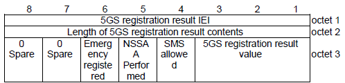
Structure of the 5GS Registration Result Field (As per 3GPP TS 24.501 - Figure 9.11.3.6.1)
-
Octet 1: Spare bits.
-
Octet 2 : Length of 5GS registraion result contents
-
Octet 3:
-
Emergency Registered (1 bit)
-
Indicates whether the UE is registered for emergency services.
-
NSSAA Performed (1 bit)
-
Indicates whether Network Slice-Specific Authentication and Authorization (NSSAA) was performed.
-
SMS Allowed (1 bit)
-
Indicates whether SMS over NAS transport is allowed.
-
5GS Registration Result Value (3 bits)
-
Provides information on the type of access granted.
Followings are decoded information element structure
5GS registration result value (3bit)
3GPP access
Non-3GPP access
3GPP access and non-3GPP access
reserved
SMS over NAS transport allowed (SMS allowed) (1bit)
SMS over NAS not allowed
SMS over NAS allowed
NSSAA to be performed : Network slice-specific authentication and authorization is to be performed
Network slice-specific authentication and authorization is not to be performed
Network slice-specific authentication and authorization is to be performed
Emergency registered
Not registered for emergency services
Registered for emergency services
Information Element Description
5GS Registration Result Value (3 bits) - This field indicates the type of access granted to the UE:
- 0 = 3GPP Access
- UE is registered for 3GPP access only.
- 1 = Non-3GPP Access
- UE is registered for non-3GPP access (e.g., Wi-Fi).
- 2 = 3GPP Access and Non-3GPP Access
- UE is registered for both 3GPP and non-3GPP access.
- 3 = Reserved
SMS Over NAS Transport Allowed (SMS Allowed) (1 bit) - Indicates whether the UE can send/receive SMS over NAS transport:
- 0 = SMS Over NAS Not Allowed
- SMS transport over NAS is not permitted for the UE.
- 1 = SMS Over NAS Allowed
- SMS transport over NAS is permitted for the UE.
NSSAA Performed (1 bit) - Indicates the status of Network Slice-Specific Authentication and Authorization (NSSAA):
- 0 = NSSAA Not Performed
- NSSAA is not required or has not been performed for this registration.
- 1 = NSSAA Performed
- NSSAA has been successfully completed for the registration procedure.
Emergency Registered (1 bit) - Indicates whether the UE is registered for emergency services:
- 0 = Not Registered for Emergency Services
- The UE is not authorized to access emergency services.
- 1 = Registered for Emergency Services
- The UE is authorized to access emergency services.
5GS network feature support
This field specifies the network features supported by the 5G system for the UE. The indicators provide information about the capabilities and services available in the network.
IMS voice over PS session over 3GPP access indicator (IMS-VoPS-3GPP)
IMS voice over PS session not supported over 3GPP access
IMS voice over PS session supported over 3GPP access
IMS voice over PS session over non-3GPP access indicator (IMS-VoPS-N3GPP)
IMS voice over PS session not supported over non-3GPP access
IMS voice over PS session supported over non-3GPP access
Emergency service support indicator for 3GPP access (EMC)
Emergency services not supported
Emergency services supported in NR connected to 5GCN only
Emergency services supported in E-UTRA connected to 5GCN only
Emergency services supported in NR connected to 5GCN and E-UTRA
Emergency service fallback indicator for 3GPP access (EMF)
Emergency services fallback not supported
Emergency services fallback supported in NR connected to 5GCN only
Emergency services fallback supported in E-UTRA connected to 5GCN only
Emergency services fallback supported in NR connected to 5GCN and E-UTRA connected to 5GCN
Interworking without N26 interface indicator (IWK N26) // 24.501-5.5.1.2.4 for description
0-Interworking without N26 interface not supported //the AMF supports N26 interface
1-Interworking without N26 interface supported //the AMF does NOT supports N26 interface
MPS indicator (MPSI)
Access identity 1 not valid in RPLMN or equivalent PLMN
Access identity 1 valid in RPLMN or equivalent PLMN
Emergency service support for non-3GPP access indicator (EMCN3)
Emergency services not supported over non-3GPP access
Emergency services supported over non-3GPP access
MCS indicator (MCSI)
Access identity 2 not valid in RPLMN or equivalent PLMN
Access identity 2 valid in RPLMN or equivalent PLMN
Information Element Description
IMS Voice Over PS Session Over 3GPP Access Indicator (IMS-VoPS-3GPP) - Indicates the support for IMS voice services over PS (Packet Switched) session on 3GPP access:
- 0 = IMS voice over PS session not supported over 3GPP access
- 1 = IMS voice over PS session supported over 3GPP access
IMS Voice Over PS Session Over Non-3GPP Access Indicator (IMS-VoPS-N3GPP) - Indicates the support for IMS voice services over PS session on non-3GPP access:
- 0 = IMS voice over PS session not supported over non-3GPP access
- 1 = IMS voice over PS session supported over non-3GPP access
Emergency Service Support Indicator for 3GPP Access (EMC) - Specifies whether emergency services are supported over 3GPP access:
- 0 = Emergency services not supported
- 1 = Emergency services supported
Emergency Service Support Indicator for Non-3GPP Access - Specifies whether emergency services are supported over non-3GPP access:
- 0 = Emergency services not supported over non-3GPP access
- 1 = Emergency services supported over non-3GPP access
Emergency Service Fallback Indicator for 3GPP Access (EMF) - Indicates the fallback support for emergency services:
- 0 = Emergency services fallback not supported
- 1 = Emergency services fallback supported
- In NR connected to 5GCN only
- In E-UTRA connected to 5GCN only
- In NR connected to 5GCN and E-UTRA connected to 5GCN
Interworking Without N26 Interface Indicator (IWK N26) - Specifies whether the N26 interface is supported for interworking between 5GC and EPC (Evolved Packet Core):
- 0 = Interworking without N26 interface not supported
- The AMF support the N26 interface.
- 1 = Interworking without N26 interface supported
- The AMF does not support the N26 interface.
MPS Indicator (MPSI) - Indicates the validity of the MPS (Mission-Critical Push-to-Talk Service) identity:
- 0 = Access identity not valid in RPLMN (Registered Public Land Mobile Network) or equivalent PLMN
- 1 = Access identity valid in RPLMN or equivalent PLMN
Emergency Service Support for Non-3GPP Access Indicator (EMC3) - Specifies the support for emergency services on non-3GPP access:
- 0 = Emergency services not supported over non-3GPP access
- 1 = Emergency services supported over non-3GPP access
MCS Indicator (MCSI) - Indicates the validity of the MCS (Mission-Critical Service) identity:
- 0 = Access identity not valid in RPLMN or equivalent PLMN
- 1 = Access identity valid in RPLMN or equivalent PLMN
5GS update type
This field provides information on specific update requests or requirements related to 5G services. It helps the network determine the type of update the UE is requesting.
SMS over NAS transport requested (SMS requested)
0 SMS over NAS not supported
1 SMS over NAS supported
NG-RAN Radio Capability Update (NG-RAN-RCU)
0 NG-RAN radio capability update not needed
1 NG-RAN radio capability update needed
Information Element Description
SMS Over NAS Transport Requested (SMS Requested) - Indicates whether the SMS over NAS transport is requested by the UE.
- 0 = SMS Over NAS Not Supported
- The UE does not request SMS services via NAS transport.
- 1 = SMS Over NAS Supported
- The UE requests SMS services via NAS transport.
NG-RAN Radio Capability Update (NG-RAN-RCU) - Specifies whether a radio capability update is needed for the NG-RAN (Next Generation Radio Access Network).
- 0 = NG-RAN Radio Capability Update Not Needed
- The UE does not require a radio capability update in the NG-RAN.
- 1 = NG-RAN Radio Capability Update Needed
- The UE requests a radio capability update in the NG-RAN, typically due to changes in radio features or capabilities.
Allowed NSSAI
The Allowed NSSAI indicates the network slice(s) that the mobile device is allowed to use based on the network's policy and available resources. To understand the role of this IE in the context of real 5G operation, you need to have a good understandings on Network Slicing. I would recommend you to check out the note on Network Slicing for further details.
< 24.501 - Figure 9.11.3.37.1: NSSAI information element >
< 24.501 - Figure 9.11.2.8.1: S-NSSAI information element >
Allowed PDU session status
This field indicates whether the user-plane resources of a PDU (Protocol Data Unit) session are allowed to be re-established over 3GPP access. This field provides critical information for managing session continuity and resource re-establishment in 5G networks
All 0 : indicates that the user-plane resources of corresponding PDU session is not allowed to be
re-established over 3GPP access.
All 1 : indicates that the user-plane resources of corresponding PDU session can be re-established
over 3GPP access.
Information Element Description
All 0 - Indicates that the user-plane resources of the corresponding PDU session are not allowed to be re-established over 3GPP access.
- The session remains inactive or terminated unless re-established through other procedures.
All 1 - Indicates that the user-plane resources of the corresponding PDU session can be re-established over 3GPP access.
- This allows for the restoration of user-plane functionality for that PDU session.
Configured NSSAI
24.501-8.2.7.7 states :
The network may include this IE if the network needs to provide the UE with a new configured NSSAI for the current PLMN or SNPN.
To understand the role of this IE in the context of real 5G operation, you need to have a good understandings on Network Slicing. I would recommend you to check out the note on Network Slicing for further details.
< 24.501 - Figure 9.11.3.37.1: NSSAI information element >
< 24.501 - Figure 9.11.2.8.1: S-NSSAI information element >
LADN(Local Area Data Network) Indication
LADN DNN value 1
LADN DNN value 2
...
LADN DNN value n
LADN information
LADN 1
DNN Value (24.501 - 9.11.2.1A)
5GS tracking area identity list
LADN 2
DNN Value
5GS tracking area identity list
....
LADN n
DNN Value
5GS tracking area identity list
MICO(Mobile Initiated Connection Only) indication
0 : all PLMN registration area not allocated
1 : all PLMN registration area allocated
Network slicing indication
24.501-9.11.3.36 states as follows :
The purpose of the Network slicing indication information element is to indicate additional information associated with network slicing in the generic UE configuration update procedure and the registration procedure, other than the user's configured NSSAI, allowed NSSAI, pending NSSAI and rejected NSSAI information.
< 24.501-Figure 9.11.3.36.1: Network slicing indication >

Network slicing subscription change indication (NSSCI) - octat 1, bit 1
0 Network slicing subscription not changed
1 Network slicing subscription changed
Default configured NSSAI indication (DCNI) - octat 1, bit 2
0 Requested NSSAI not created from default configured NSSAI
1 Requested NSSAI created from default configured NSSAI
In the UE to network direction bit 1 is spare. The UE shall set this bit to zero.
In the network to UE direction bit 2 is spare. The network shall set this bit to zero.
Bits 3 and 4 are spare and shall be coded as zero.
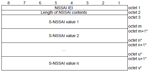
NSSAI (Network Slice Selection Assistance Information)
24.501-9.11.3.37 states as follows :
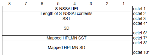
The purpose of the NSSAI information element is to identify a collection of S-NSSAIs
< 24.501 - Figure 9.11.3.37.1: NSSAI information element >
The NSSAI is a type 4 information element with a minimum length of 4 octets and a maximum length of 146 octets.
S-NSSAI value 1
SST (Slice/Service Type)
SD (Slide Differentiator)
Mapped HPLMN SST
Mapped HPLMN SD
S-NSSAI value 2
SST (Slice/Service Type)
SD (Slide Differentiator)
Mapped HPLMN SST
Mapped HPLMN SD
....
S-NSSAI value N
SST (Slice/Service Type)
SD (Slide Differentiator)
Mapped HPLMN SST
Mapped HPLMN SD
NSSAI(Network Slice Selection Assistance Information) inclusion mode
24.501-9.11.3.37A States as follows :
The purpose of the NSSAI inclusion mode information element is to indicate the NSSAI inclusion mode in which the UE shall operate.
< 24.501 - Figure 9.11.3.37A.1: NSSAI inclusion mode information element >
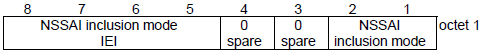
[bit(2),bit(1)] = [0,0] : NSSAI inclusion mode A
[bit(2),bit(1)] = [0,1] : NSSAI inclusion mode B
[bit(2),bit(1)] = [1,0] : NSSAI inclusion mode C
[bit(2),bit(1)] = [1,1] : NSSAI inclusion mode D
Operator-defined access category definitions
Operator-defined access category definition 1
Precedence value
Operator-defined access category number
PSAC
Standardized access category field is not included
Standardized access category field is included
Length of criteria
Criteria
DNN type
OS id + OS App Id type
S-NSSAI type
Standardized access category
Operator-defined access category definition 2
Precedence value
Operator-defined access category number
PSAC
Standardized access category field is not included
Standardized access category field is included
Length of criteria
Criteria
DNN type
OS id + OS App Id type
S-NSSAI type
Standardized access category
....
Operator-defined access category definition n
Precedence value
Operator-defined access category number
PSAC
Standardized access category field is not included
Standardized access category field is included
Length of criteria
Criteria
DNN type
OS id + OS App Id type
S-NSSAI type
Standardized access category
PDU session status
The purpose of the PDU session status information element is to indicate the state of each PDU session that can be identified by a PDU session identity(PSI). This indicates a specific PDU session is currently active or not
This IE carriies a bitmap of 16 bits as labeled below.
PSI(7),PSI(6),PSI(5),PSI(4),PSI(3),PSI(2),PSI(1),PSI(0)
PSI(15),PSI(14),PSI(13),PSI(12),PSI(11),PSI(10),PSI(9),PSI(8)
0 or 1 for each bit indicates followings.
0 : indicates that the 5GSM state of the corresponding PDU session is PDU SESSION INACTIVE.
1 : indicates that the 5GSM state of the corresponding PDU session is not PDU SESSION INACTIVE
PDU session reactivation result
This IE carriies a bitmap of 16 bits as labeled below.
PSI(7),PSI(6),PSI(5),PSI(4),PSI(3),PSI(2),PSI(1),PSI(0)
PSI(15),PSI(14),PSI(13),PSI(12),PSI(11),PSI(10),PSI(9),PSI(8)
0 or 1 for each bit indicates followings.
0 : indicates establishment of user-plane resources of the PDU session was not requested in the Uplink data status IE or establishment of user-plane resources of the PDU session was not allowed in the Allowed PDU session status IE or establishment of user-plane resource of the PDU session is successful.
1 : indicates either establishment of user-plane resources of the PDU session was requested in the Uplink data status IE but establishment of user-plane resource of the PDU session is not successful or indicates establishment of user-plane resources of the PDU session was allowed in the Allowed PDU session status IE butestablishment of user-plane resource of the PDU session is either not performed or not successful.
PDU session reactivation result error cause
PDU session ID 1
cause value 1 (8 bit)
PDU session ID 2
cause value 2
...
PDU session ID N
cause value N
Requested NSSAI
The Requested NSSAI is used to inform the 5G core network about the network slice(s) that the mobile device is requesting to use. To understand the role of this IE in the context of real 5G operation, you need to have a good understandings on Network Slicing. I would recommend you to check out the note on Network Slicing for further details.
< 24.501 - Figure 9.11.3.37.1: NSSAI information element >
< 24.501 - Figure 9.11.2.8.1: S-NSSAI information element >
Service type
Service type value (4 bit)
signalling
data
mobile terminated services
emergency services
emergency services fallback
high priority access
elevated signalling
unused; shall be interpreted as "signalling", if received by the network
unused; shall be interpreted as "signalling", if received by the network
unused; shall be interpreted as "data", if received by the network
unused; shall be interpreted as "data", if received by the network
unused; shall be interpreted as "data", if received by the network
UE status
EMM registration status (S1 mode reg)
0 UE is not in EMM-REGISTERED state
1 UE is in EMM-REGISTERED state
5GMM registration status (N1 mode reg)
0 UE is not in 5GMM-REGISTERED state
1 UE is in 5GMM-REGISTERED state
Uplink Data Status
This IE carriies a bitmap of 16 bits as labeled below. This field indicates the status of uplink data for various PDU sessions. PSI stands for PDU Session ID and the 'n' in PSI(n) indicates the PDU Session ID number.
PSI(7),PSI(6),PSI(5),PSI(4),PSI(3),PSI(2),PSI(1),PSI(0)
PSI(15),PSI(14),PSI(13),PSI(12),PSI(11),PSI(10),PSI(9),PSI(8)
PSI(n) is set to be 0 or 1 which indicates followings.
0 : indicates that no uplink data are pending for the corresponding PDU session identity.
1 : indicates that uplink data are pending for the corresponding PDU session identity.
Reference
[1] 5G Standalone Access Registration Signaling Messages
[2] 5G Standalone Access: Registration Procedure