|
PUCCH / UCI in Detail
PUCCH is an uplink physical channel that carries UCI (Uplink Control Information). As DCI (Downlink Control Information) is carried by PDCCH, UCI is carried by PUCCH. A big difference between DCI and UCI is that UCI can be carried either by PUCCH or PUSCH depending on situation whereas DCI can be carried only by PDCCH (not by PDSCH in any case).
- UCI
- Summary PUCCH Formats
- Which format to use ?
- How to Determine PUCCH location ?
- How to define PUCCH baseband signal ?
- PUCCH Base Sequence Generation
- Group and sequence hopping
- Cyclic Shift
- PUCCH Format 0 Baseband Sequence
- PUCCH Format 1 Baseband Sequence
- PUCCH Format 2 Baseband Sequence
- PUCCH Format 3 Baseband Sequence
- PUCCH Format 4 Baseband Sequence
- Baseband Parameters for PUCCH Format
- Frequeny Hopping
- PUCCH Resource Element Mapping Examples
- Format 0
- Format 1 : Ex 01
- Format 1 : Ex 02
- Format 2 : Ex 01
- Format 3 : Ex 01
- Format 3 : Ex 02
- Format 3 : Ex 03
- Format 3 : Ex 04
- Format 4 : Ex 01
- Format 4 : Ex 02
- Format 4 : Ex 03
- Format 4 : Ex 04
- Modulation
- Channel Coding
- UCI / PUSCH Multiplexing
- What is PUCCH Resource and what constitues it ?
- How does UE figure out which resource to apply ?
- How the PUCCH Resource allocation is determined ?
- < Case 1 > Using the predefined table : Before PUCCH-Config in RRC
- < Case 2 > Using the table defined in RRC message : After PUCCH-Config in RRC
- PUCCH Encoding
- Step 1 : UCI Payload Construction
- Step 2 : UCI Channel Coding and Rate Matching
- PUCCH Format 0 Encoding
- PUCCH Format 1 Encoding
- PUCCH Format 2 Encoding
- PUCCH Format 3 Encoding
- PUCCH Format 4 Encoding
- Resource Element Mapping
- What the Encoder and Decoder Must Agree On
- PUCCH Decoding
- PUCCH Format 0 Decoding
- PUCCH Format 1 Decoding
- PUCCH Format 2 Decoding
- PUCCH Format 3 Decoding
- PUCCH Format 4 Decoding
- UCI Output after PUCCH Decoding
- Examples
- RRC Parameters
- Amarisoft Tech-Academy Tutorial
UCI
The main purpose of PUCCH is to carry UCI (Uplink Control Information). Even though UCI can be taken as a part of PUCCH, I wrote a separate page here for UCI since it is a huge topics on its own (PUCCH is not the only channel that carries UCI, depending on cofiguration PUSCH also carries UCI. So it is reasonable to write a separate page for UCI)
Summary of PUCCH Formats
There are multiple PUCCH formats (0, 1, 2, 3, 4), each optimized for different amounts of UCI bits and different time–frequency resources. These formats differ mainly in:
- The number of OFDM symbols used,
- The number of bits carried,
- Whether or not they use orthogonal cover codes (OCC),
- Whether or not they use transform precoding,
- How the sequences are generated or spread across the assigned PRBs.
There are 5 different formats of PUCCH and which one of them is used is determined by how many bits of information should be carried and how many symbols are assigned, as summarized in the following table.
< Based on 38.211 - Table 6.3.2.1-1: PUCCH formats.>
|
Format Types |
RP-180990 |
Lengh of Symbols |
Number of bits |
Descriptions (based on 38.300 - 5.3.3) |
|
Format 0 |
|
1~2 |
<= 2 |
|
|
Format 1 |
|
4~14 |
<= 2 |
|
|
Format 2 |
|
1~2 |
> 2 |
|
|
Format 3 |
|
4~14 |
> 2 |
|
|
Format 4 |
|
4~14 |
> 2 |
|


I think the description from 38.300 - 5.3.3 would give you another aspects of the description as below.
The short PUCCH format of up to two UCI bits is based on sequence selection, while the short PUCCH format of more than two UCI bits frequency multiplexes UCI and DMRS. The long PUCCH formats time-multiplex the UCI and DMRS. Frequency hopping is supported for long PUCCH formats and for short PUCCH formats of duration of 2 symbols. Long PUCCH formats can be repeated over multiple slots.
Following is the summary of PUCCH formats with more detailed parameter. For the overview of PUCCH parameters, I think this table would be enough but if you want to know of the detailed meaning of each of these parameters, you would need to go through the whole page.
|
Parameter |
Format 0 |
Format 1 |
Format 2 |
Format 3 |
Format 4 |
|
UCI Bit Length |
<= 2 |
<= 2 |
> 2 |
> 2 |
> 2 |
|
PUCCH Length |
Short |
Long |
Short |
Long |
Long |
|
UE Multiplexing in Same PRB |
YES (CS) |
YES (CS&OCC) |
NO |
NO |
YES (PreDFT OCC) |
|
UCI/DMRS Multiplexing Method |
N/A |
TDM |
FDM |
TDM |
TDM |
|
starting PRB/PRB offset |
PRB-Id |
PRB-Id |
PRB-Id |
PRB-Id |
PRB-Id |
|
nrofPRBs |
1 |
1 |
1~16 |
1~16 |
1 |
|
intraSlotFrequencyHopping |
enabled |
enabled |
enabled |
enabled |
enabled |
|
secondHopPRB |
PRB-Id |
PRB-Id |
PRB-Id |
PRB-Id |
PRB-Id |
|
startingSymbolIndex |
0~13 |
0~10 |
0~13 |
0~10 |
0~10 |
|
nrofSymbols |
1~2 |
4~14 |
1~2 |
4~14 |
4~14 |
|
initialCyclicShift |
0~11 |
0~11 |
N/A |
N/A |
N/A |
|
timeDomainOCC |
N/A |
0~6 |
N/A |
N/A |
N/A |
|
occ-Length |
N/A |
N/A |
N/A |
N/A |
2,4 |
|
occ-Index |
N/A |
N/A |
N/A |
N/A |
0,1,2,3 |
|
interslotFrequencyHopping |
N/A |
enabled |
enabled |
enabled |
enabled |
|
additionalDMRS |
N/A |
true |
true |
true |
true |
|
maxCodeRate |
N/A |
|
|
|
|
|
nrofSlots |
N/A |
2,4,8 |
2,4,8 |
2,4,8 |
2,4,8 |
|
pi2BPSK |
N/A |
enabled |
enabled |
enabled |
enabled |
|
simultaneousHARQ_ACK_CSI |
N/A |
true |
true |
true |
true |
Some background of adopting this kind of design is briefly described in V-B of this paper as follows
Unlike LTE PUCCH that is located at the edges of the carrier bandwidth and is designed with fixed duration and timing,
The two tables above describe what each format is and which RRC parameters configure it. The table below compares them on the points those tables do not cover – how the information is actually carried, which channel code is applied, the waveform and reference-signal structure, and what each format is good and bad at.
< Comparison of PUCCH formats – coding, structure and trade-offs >
|
Aspect |
Format 0 |
Format 1 |
Format 2 |
Format 3 |
Format 4 |
|
How the |
Sequence selection. The bits are not modulated onto anything – they select the cyclic shift of a low-PAPR base sequence (38.211-6.3.2.3.1, 38.213-9.2.3). |
A single modulated symbol multiplies the whole low-PAPR sequence, which is then spread over the symbols by a time-domain OCC. |
Coded bits are scrambled, QPSK modulated and mapped directly onto the data subcarriers. |
Coded bits are scrambled, modulated, then transform precoded (DFT-spread) before mapping. |
As format 3, plus block-wise spreading by an OCC across the PRB before the transform. |
|
Channel coding |
None. There is no coded bit sequence at all – the information is the cyclic shift. |
None. The 1 or 2 bits are modulated directly; no block code is applied. |
By payload size A (identical for formats 2/3/4): |
Same as format 2 – the regime is chosen by A, never by the format. |
Same as format 2 – the regime is chosen by A, never by the format. |
|
Modulation |
n/a (sequence based) |
BPSK for 1 bit, QPSK for 2 bits |
QPSK only |
QPSK, or π/2-BPSK if pi2BPSK is configured |
QPSK, or π/2-BPSK if pi2BPSK is configured |
|
Waveform |
CP-OFDM |
CP-OFDM |
CP-OFDM |
DFT-s-OFDM (transform precoding) |
DFT-s-OFDM (transform precoding) |
|
Reference |
No DMRS. The transmitted sequence is itself known to the gNB, so detection is a correlation against the candidate shifts. |
DMRS occupies alternate symbols (TDM with data). |
DMRS is FDM’d inside the same symbol – subcarriers 1, 4, 7, 10 of every PRB (k mod 3 = 1), leaving 8 of the 12 subcarriers for data. |
DMRS occupies whole dedicated symbols (Table 6.4.1.3.3.2-1). |
DMRS occupies whole dedicated symbols, with the cyclic shift keyed by occ-Index (Table 6.4.1.3.3.1-1). |
|
Multiplexing |
Cyclic shift only – and the payload consumes shifts: 1 bit uses mCS∈{0,6}, 2 bits uses {0,3,6,9}. So of 12 shifts only 6 UEs (1 bit) or 3 UEs (2 bits) fit. |
Cyclic shift × time-domain OCC → the highest multiplexing of all formats (see the ~12 UE figure above). |
None. One UE per resource. |
None without interlaced mapping. One UE per resource. |
Block-wise OCC, occ-Length 2 or 4 → 2 or 4 UEs share one PRB. |
|
Frequency |
1 PRB (fixed) |
1 PRB (fixed) |
1–16 PRB |
1–16 PRB, but only values of the form 2α2·3α3·5α5 (so 7, 11, 13, 14… are not allowed) |
1 PRB (fixed) – there is no nrofPRBs field for format 4 at all, and it is then divided by the OCC length. |
|
Pros |
Cheapest resource of all (1–2 symbols, no DMRS); very low latency; robust detection for its size. |
Long duration → best coverage per bit; the highest UE multiplexing; simple receiver. |
Short → low latency; payload scales with PRBs; good when SNR is high. |
Highest payload capacity (up to 16 PRB × 14 symbols); DFT-s-OFDM keeps PAPR low, which helps the UE’s power amplifier and therefore coverage. |
Combines long-duration coverage with multi-UE sharing of a single PRB – the only format that does both. |
|
Cons |
≤2 bits only; the payload eats multiplexing capacity; non-coherent detection needs more SNR per bit; cannot carry CSI. |
≤2 bits only, yet it occupies up to 14 symbols – very low spectral efficiency per bit. |
No UE multiplexing; the least energy of any format → the worst coverage; CP-OFDM has higher PAPR than the DFT-s-OFDM formats. |
No UE multiplexing (non-interlaced); the allowed PRB counts are restricted; long duration costs latency. |
The lowest capacity of the >2-bit formats – 1 PRB divided by 2 or 4. It is a multiplexing format, not a high-payload one. |
|
Typical use |
1–2 bit HARQ-ACK, SR. |
1–2 bit HARQ-ACK / SR when coverage matters more than latency. |
Small-to-medium CSI reports and multi-bit HARQ-ACK at good SNR. |
Large CSI reports, large HARQ-ACK codebooks, cell-edge UEs. |
Multi-bit UCI from several cell-edge UEs sharing one PRB. |
- ★ The channel code is chosen by the payload size, not by the format. Formats 2, 3 and 4 all run the same clause-6.3.1 chain: Reed-Muller below 12 bits, Polar at 12 bits and above. It is a common misreading that the “bigger” formats use a stronger code – they do not; a 7-bit CSI report is Reed-Muller whether it goes on format 2, 3 or 4.
- ★ Format 4 is the smallest of the >2-bit formats, not the biggest. In TS 38.331 PUCCH-format3 carries nrofPRBs (1..16) while PUCCH-format4 has no such field – it is one PRB, then divided by occ-Length. Format 4 exists to let several UEs share a PRB, which is exactly why it gives up capacity to do it.
- ★ Format 0 spends its multiplexing capacity on the payload. Because the cyclic shift is the information (38.213 Tables 9.2.3-3/9.2.3-4), the 12 available shifts are split between UEs and the ACK value – which is why a 2-bit format-0 resource is limited to 3 UEs where a 1-bit one holds 6.
- ★ Only formats 3 and 4 are transform precoded. That is what gives them the lower PAPR of the group, and it is also why their receivers need an inverse DFT that formats 0/1/2 do not.
Which format to use ?
- Obviously the first criteria would be how many UCI bits you need to carry. As you see in the table above, there are two groups to chose for this critera. When the UCI bits is 2 or lower, you can use Format 0 or 1. When the UCI bits are greater 3 or higher, you can use format 2,3,4.
- Then next criteria would be about the possibility of UE multiplexing in the same PRB. Format 0,1,4 allows the multiplexing and format 2,3 does not allow the multiplexing.
- Then another criteria you can think of would be the robustness in various radio channel condition. In general, sequence based PUCCH would be more robust than the DMRS based one. Even with the same format, the robustness would vary depending on the number of bit length or number of DMRS as shown in Physical Uplink Control Channel Design for 5G NewvRadio
How to Determine PUCCH location ?
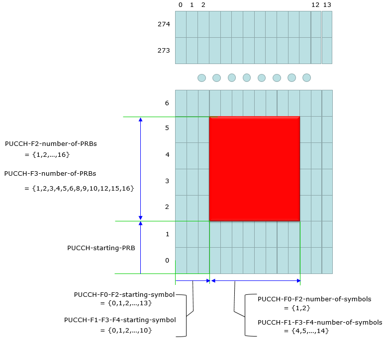
Following is the illustration for the description on 38.213 - 9.2.1 PUCCH Resource Sets. As you see in the following illustration, some parameters applies to all PUCCH format but some parameters applies to only specific formats as below.
- number of PRBs : Applies to only PUCCH format 2 and 3 (See PUCCH-format2, PUCCH-format3 in RRC) .
- starting PRB : Applies to all PUCCH Format (See PUCCH-Resource in RRC)
- starting symbol : Applies to all PUCCH format, but range of values varies depending the format( See PUCCH-format0, PUCCH-format1, PUCCH-format2, PUCCH-format3, PUCCH-format4)
- number of symbols : Applies to all PUCCH format, but range of values varies depending the format( See PUCCH-format0, PUCCH-format1, PUCCH-format2, PUCCH-format3, PUCCH-format4)
How to define PUCCH baseband signal ?
As in LTE PUCCH(format 1,1a,1b, format 2,2a,2b and format 3), the baseband generation process for NR PUCCH is also very complicated. As you know, all the purpose of PUCCH is just to send a few bits to gNB. I've been thinking on why we need this kind of complicated way just to send a few bits.
Actually PUCCH is not the only one that is designed in such a complicated way. Every channel processing in cellular technology is complicated. Main reason behind this complexity is for reliability of the delivery of the contents and for some channels we put some additional complication for handling multiple users with very limited physical resources.
Anyway, I don't think I can explain fully about the design concept of PUCCH baseband generation in plain words and I don't want to pretend that I myself knows about the full detail.
Full understanding on this process will be required only for a few physical layer development engineer and those engineer would not need this type of notes since they've already had bettern knowledge than I just by reading 3GPP documents.
The main purpose of writing this note is to make a cheat sheet for overall PUCCH baseband process and figure out the link between RRC parameter and baseband process. Even if I don't completely understand the process, at least I can say 'Hmm... this RRC parameter seems to be related to this part of the baseband process'.
PUCCH baseband process is made up of roughly three steps :
This three steps applies to all PUCCH formats (Format 0,1,2,3,4) but depending on PUCCH format a little different parameters(see here) are used during this process and some format would require some extra steps in addition to this common part.
PUCCH Base Sequence Generation
PUCCH Baseband Sequence Generation refers to how the physical uplink control channel (PUCCH) waveform is formed in baseband before being transmitted over the air.
It covers
-
(i) how the bits are scrambled and modulated;
-
(ii) how the reference or sequence signals are generated (for PUCCH formats 0, 1, 3, and 4);
-
(iii) how symbol spreading is done (for formats 1, 2, 3, 4); and
-
(iv) how everything is then mapped onto the allocated resource elements. Below is a step-by-step explanation, focusing on the key ideas of sequence generation for each PUCCH format.
PUCCH formats 0, 1, 3, and 4 use sequences r(α, δ)u,v(n) given by clause 38.211-5.2.2 with δ = 0, where the sequence group u and the sequence number v depend on the sequence hopping in clause 38.211-6.3.2.2.1, and the cyclic shift α depends on the cyclic shift hopping in clause 6.3.2.2.2.
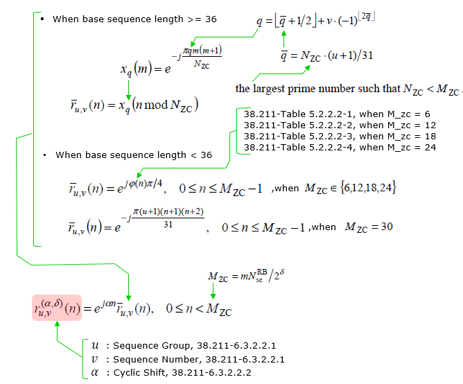
In PUCCH formats 0, 1, 3, and 4, the waveform is built around a Zadoff–Chu-like complex sequence ru,v(α,δ)(n). Here:
- u (group index) may change per slot according to group hopping.
- v (sequence index) can also be varied if sequence hopping is enabled.
- α (cyclic shift) can be updated on a symbol-by-symbol basis to introduce cyclic shift hopping.
The sequence ru,v(α,δ)(n) can be generated or hopped using pseudo-random initializations that depend on the cell identity (NIDcell) or a higher-layer configured ID. This approach helps ensure good autocorrelation and cross-correlation properties among different UEs and different PUCCH transmissions.
Group and sequence hopping
Hopping in the PUCCH (Physical Uplink Control Channel) context refers to the mechanism of dynamically altering parameters to improve performance and mitigate interference in the uplink. The hopping mechanism consists of two main components: group hopping and sequence hopping.
Group hopping modifies the frequency group used by the uplink signal, reducing interference and ensuring more robust communication. The value of the hopping group, denoted as fgh, depends on the configuration parameters set by the network, such as the hoppingId or the cell identity NcellID. If group hopping is disabled, fgh is set to zero.
Sequence hopping involves altering the base sequence of the uplink signal to ensure diversity and enhance resilience against fading. The sequence hopping component, represented by fss, is derived from the network configuration. The hopping sequence depends on whether group hopping is enabled, disabled, or set to neither.
The hopping behavior is summarized by the formula:
u = (fgh + fss) mod 30
In this equation, the effective hopping parameter u combines the group hopping and sequence hopping values to determine the uplink resource allocation dynamically. This ensures efficient utilization of the available spectrum while minimizing interference.
Additionally, a frequency hopping index, nhop, plays a role in determining intra-slot hopping behavior. When frequency hopping is disabled, nhop is set to zero. When enabled, nhop alternates between zero for the first hop and one for the second hop within a slot.
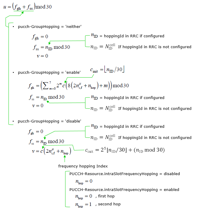
The formula for determining the hopping value is:
u = (fgh + fss) mod 30
Here, the behavior depends on the value of pucch-GroupHopping, which can be set to 'neither', 'enable', or 'disable'. The following describes each scenario:
When pucch-GroupHopping is set to 'neither', it indicates that no group hopping or sequence hopping is enabled. In this configuration: This configuration effectively disables both group and sequence hopping, resulting in static behavior where no dynamic hopping is applied. The values of the parameters are derived from either the RRC configuration or the cell identity, ensuring deterministic operation in the absence of hopping.
- fgh = 0
- fss = nID mod 30
- nID = hoppingId in RRC if configured
- nID = NcellID if hoppingId in RRC is not configured
- v = 0
Following is the high level description of the parameter setting for this condition
- Group Hopping Parameter (fgh): The value of the group hopping parameter is set to 0, meaning no group hopping is applied.
- Sequence Hopping Parameter (fss): This is determined by the formula nID mod 30, where:
- nID is either the hoppingId provided in the RRC configuration if it is explicitly configured.
- If hoppingId is not configured in the RRC, nID defaults to the cell identity NcellID.
- Additional Parameter (v): The parameter v is set to 0, which indicates that there is no further adjustment or modification to the hopping behavior.
When pucch-GroupHopping is set to 'enable', the configuration activates group hopping in PUCCH (Physical Uplink Control Channel).
The configuration for PUCCH (Physical Uplink Control Channel) Group Hopping when set to 'enable' introduces frequency hopping, allowing sequences to span multiple frequency groups. This improves diversity and robustness against interference.
When pucch-GroupHopping is set to 'enable', it ensures that the uplink signal spans different frequency groups to enhance interference resilience and provide diversity in transmission. The formula for fgh incorporates multiple variables, including hopping-related parameters and a summation over predefined ranges, making it flexible and adaptive to the system's configuration. fss and cinit are derived from system identifiers, ensuring unique and non-colliding sequence configurations for different cells.
- fgh = (Σ7m=0 2m c(8(2nsfμ + nhop) + m))) mod 30
- fss = nID mod 30
- cinit = ⌊nID/30⌋
- v = 0
The parameters for this configuration are as follows:
- Frequency group hopping factor (fgh):
- fgh is computed using a summation-based formula:
- fgh = (Σ7m=0 2m c(8(2nsfμ + nhop) + m))) mod 30
- nsfμ is the slot index within a subframe for the given numerology μ.
- nhop is the hopping index (can be 0 or 1 based on frequency hopping configuration).
- Sequence shift factor (fss): Hopping Parameter
- fss = nID mod 30
- nID is the hopping ID configured in the RRC (Radio Resource Control).
- If not explicitly configured, nID defaults to the cell ID (NIDcell).
- Initial value for the sequence (cinit):
- cinit = ⌊nID / 30⌋
- This is used as the initial value for the pseudo-random sequence generation function.
- Frequency hopping index (v):
- The index v is set to 0.
- In this case, v = 0, which implies no further modifications or shifts in the hopping sequence.
This calculation involves:
Summation over 8 terms: Each term is weighted by 2m, where m ranges from 0 to 7.
c(x): Represents a pseudo-random sequence generator function, which depends on:
8 · (2nsfμ + nhop) + m, where:
The result is taken modulo 30 to ensure the parameter fits within the range for group hopping.
When pucch-GroupHopping is set to 'disable', the hopping mechanism is simplified.
- fgh = 0
- fss = nID mod 30
- v = c(2nsfμ + nhop)
- cinit = 25 ⌊nID/30⌋ + (nID mod 30)
Following is the descriptions about each parameter settings
- Group Hopping Parameter (fgh):
The group hopping parameter is set to 0, meaning no group hopping is applied.
- Sequence Hopping Parameter (fss):
Calculated as:
fss = nID mod 30
Where:
- nID is the hopping ID configured in the RRC (Radio Resource Control).
- If not explicitly configured, nID defaults to the cell ID (NIDcell).
- Additional Parameter (v):
Derived as:
v = c(2nsfμ + nhop)
Where:
- nsfμ is the slot index within a subframe for the given numerology \(μ\).
- nhop is the hopping index (0 or 1 based on frequency hopping configuration).
- Initialization Parameter (cinit):
Derived as:
cinit = 25 ⌊ nID/30 ⌋ + (nID mod 30)
This is used as the initial value for the pseudo-random sequence generation function.
- nhop = 0 if PUCCH-Resource.intraSlotFrequencyHopping = disabled
- nhop = 0 for the first hop, and nhop = 1 for the second hop if PUCCH-Resource.intraSlotFrequencyHopping = enabled
Cyclic Shift
Cyclic Shift in PUCCH is a critical parameter used in 5G NR to enable multiple User Equipments (UEs) to transmit over the same resources without causing interference. It applies a phase rotation to the base sequence, enabling efficient resource multiplexing. The cyclic shift ensures orthogonality and supports multiple UEs on the same PUCCH resource. It avoids conflicts by applying dynamic phase rotations using the parameters defined above.

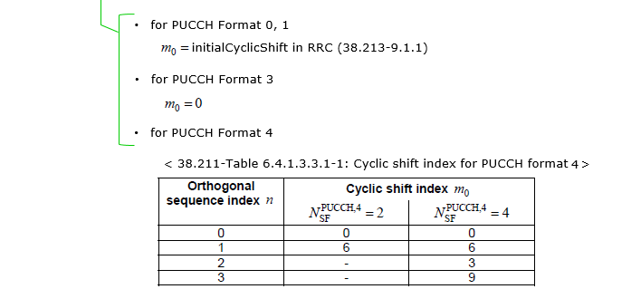
Below is a detailed explanation:
The formula for cyclic shift (αl) is:
αl = (2π/NRBSC) · ((m0 + mcs + ncs(nμs,f, l, l')) mod NRBSC)
Where:
- NRBSC: Number of resource blocks.
- m0: Initial cyclic shift parameter, varies based on PUCCH format.
- mcs: Sequence cyclic shift, determined by HARQ-ACK values or RRC signaling.
-
ncs: Additional cyclic shift calculated dynamically as:
ncs(nμs,f, l, l') = Σm=07 2m c(8Nslotsymbnμs,f + 8l + m)- c(x): Pseudo-random sequence generator based on cinit, derived as cinit = nID.
- nID: Hopping ID configured in RRC or derived from NcellID.
Followings are specific parameters for each PUCCH formats
- m0 = initialCyclicShift configured in RRC signaling.
- HARQ-ACK determines sequence cyclic shift (mcs) based on following tables
The tables presented correspond to the cyclic shift parameters for HARQ-ACK values in PUCCH (Physical Uplink Control Channel) configurations. These tables are essential for determining how sequence cyclic shifts are applied to PUCCH resources in 5G systems. The selection of the cyclic shift depends on the HARQ-ACK values, ensuring the integrity and proper alignment of control information during uplink communication. The shifts (m<sub>CS</sub>) effectively modulate the uplink signal to manage multiple users and configurations efficiently.
< 38.213-Table 9.2.3-3 Mapping of values for one HARQ-ACK information bit to sequences for PUCCH format 0>
|
HARQ-ACK Value |
0 |
1 |
|---|---|---|
|
Sequence cyclic shift |
mCS = 0 |
mCS = 6 |
< 38.213-Table 9.2.3-4 Mapping of values for two HARQ-ACK information bits to sequences for PUCCH format 0>
|
HARQ-ACK Value |
{0, 0} |
{0, 1} |
{1, 1} |
{1, 0} |
|---|---|---|---|---|
|
Sequence cyclic shift |
mCS = 0 |
mCS = 3 |
mCS = 6 |
mCS = 9 |
- m0 = 0 (default setting).
- Cyclic shift index (m0) depends on orthogonal sequence index (n) and is defined in following table
This table provides the cyclic shift indices (m0) for different orthogonal sequence indices (n) in the context of PUCCH format 4
< 38.211-Table 6.4.1.3.3.1-1: Cyclic shift index for PUCCH format 4 >
|
Orthogonal sequence index n |
Cyclic shift index m0 |
|
|---|---|---|
|
NPUCCH,4SF = 2 |
NPUCCH,4SF = 4 |
|
|
0 |
0 |
0 |
|
1 |
6 |
6 |
|
2 |
- |
3 |
|
3 |
- |
9 |
- Indicates the specific sequence index used for orthogonal coding in PUCCH format 4.
- Takes values from 0 to 3.
- Specified by RRC IE (occ-Index).
Orthogonal Sequence Index (n):
- Represents the amount of cyclic shift applied to the sequence.
- Dependent on the value of NPUCCH,4SF, which defines the number of slots per subframe for PUCCH format 4.
- Shown for two configurations of NPUCCH,4SF:
- NPUCCH,4SF = 2: Two slots per subframe.
- NPUCCH,4SF = 4: Four slots per subframe.
- Specified by RRC IE (occ-length).
Cyclic Shift Index (m0):
PUCCH Format 0 Baseband Sequence
The formula represents the PUCCH Format 0 Baseband Sequence, used in LTE for transmitting control information such as acknowledgments, scheduling requests, or channel quality indicators.
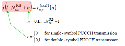
The sequence is represented as:
x(l ⋅ NscRB + n) = ru,v(α, δ)(n)
Here, the index l determines the OFDM symbol index, while n is the subcarrier index within a resource block.- l: Represents the OFDM symbol number in a slot, indicating whether the symbol is for single-symbol or double-symbol PUCCH transmission.
- NscRB: Denotes the number of subcarriers per resource block (RB).
- ru,v(α, δ)(n): Represents the Zadoff-Chu sequence used for modulation. This sequence ensures low peak-to-average power ratios (PAPR) and robust signal quality.
- n: Subcarrier index, ranging from 0 to NscRB - 1, indicating positions within a resource block.
- l: Determines the sequence structure for single-symbol or double-symbol PUCCH:
- l = 0: Used for single-symbol transmission.
- l = 0, 1: Used for double-symbol transmission.
- For single-symbol PUCCH, only the first OFDM symbol in a slot is used (l = 0).
- For double-symbol PUCCH, both the first and second OFDM symbols in a slot are used (l = 0, 1).
PUCCH Format 1 Baseband Sequence
PUCCH Format 1 introduces unique features compared to other PUCCH formats, particularly in the sequence generation process:
Unlike most other PUCCH formats that directly use the Zadoff-Chu sequence for sequence generation, PUCCH Format 1 applies an orthogonal spreading code (wi(m)) on top of the Zadoff-Chu sequence (r(α,δ)u,v(n)).
In orther words, while most other formats rely solely on the Zadoff-Chu sequence for their properties (e.g., constant amplitude, low cross-correlation), PUCCH Format 1 goes a step further by introducing spreading codes and frequency hopping for added robustness and user multiplexing. This makes it particularly suitable for scenarios requiring higher UCI bit capacity and interference mitigation.
- PUCCH Format 1 employs both modulation and spreading for robust UCI transmission.
- The orthogonal sequences ensure multiple users or control channels can coexist without interference.
- Frequency hopping (intra-slot hopping) adds diversity to improve reliability in fading environments.
- The tables provide reference mappings for implementation based on the subcarrier and symbol configurations.
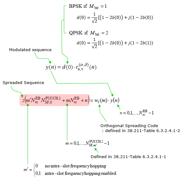
< 38.211 - Table 6.3.2.4.1-1: Number of PUCCH symbols and the corresponding  >
>
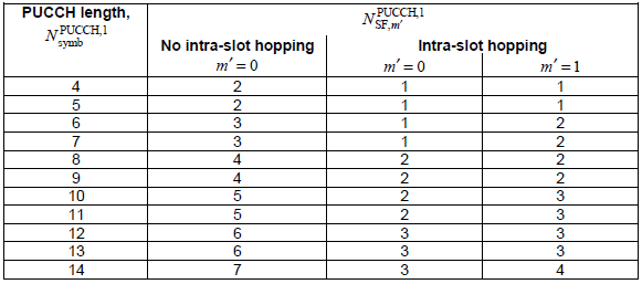
< 38.211 - Table 6.3.2.4.1-2: Orthogonal sequences 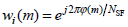 for PUCCH format 1 >
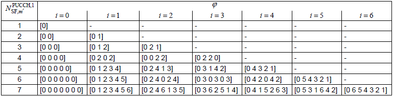
The modulated sequence is calculated as:
y(n) = d(0) · r(α,δ)u,v(n)
, where
- d(0): Represents the modulation symbol:
- BPSK (for Mbit = 1):
d(0) = 1/√2 [(1 - 2b(0)) + j(1 - 2b(0))] - QPSK (for Mbit = 2):
d(0) = 1/√2 [(1 - 2b(0)) + j(1 - 2b(1))]
- BPSK (for Mbit = 1):
- r(α,δ)u,v(n): Base sequence determined by cell-specific parameters.
The spreaded sequence is calculated as:
z(m' · NRBsc/NPUCCH,1SF,m' + m · NRBsc + n) = wi(m) · y(n)
, where
- wi(m): Orthogonal spreading code for PUCCH Format 1.
- m: Index for slot symbols.
- m': Frequency hopping parameter:
- m' = 0: No intra-slot frequency hopping.
- m' = 1: Intra-slot frequency hopping enabled.
- n: Subcarrier index (n = 0, 1, ..., NRBsc - 1).
< 38.211 - Table 6.3.2.4.1-1: Number of PUCCH symbols and the corresponding >
This table maps the number of PUCCH symbols (NPUCCH,1symb) to the corresponding values of NPUCCH,1SF,m', considering intra-slot hopping:
- No intra-slot hopping (m' = 0): The values remain consistent for single-symbol allocation.
- Intra-slot hopping (m' = 1): The values vary slightly due to hopping.
The parameter NPUCCH,1SF,m' has a specific practical meaning in the context of PUCCH Format 1 and relates to the number of subcarriers and their allocation for physical uplink control channel transmission. Its practical meaning can be described as follows:
-
NPUCCH,1SF,m' determines the number of subcarriers allocated for spreading the PUCCH Format 1 sequence. It defines how many resource elements are used within a given time and frequency grid.
-
The value of m' affects NPUCCH,1SF,m', and it indicates whether intra-slot frequency hopping is enabled:
- m' = 0: No intra-slot hopping; the subcarriers remain fixed throughout the slot.
- m' = 1: Intra-slot hopping is enabled, and subcarriers are changed mid-slot, providing additional diversity.
-
NPUCCH,1SF,m' is closely tied to the PUCCH symbol length NPUCCH,1symb. Different lengths of PUCCH symbols correspond to different values of NPUCCH,1SF,m'. This impacts how the control information is spread across the available symbols and subcarriers.
-
NPUCCH,1SF,m' plays a role in defining the orthogonal spreading sequences wi(m) applied to the baseband sequence. A larger value of NPUCCH,1SF,m' enables more orthogonal sequences, allowing for multiplexing of multiple UEs within the same resource block.
-
By varying NPUCCH,1SF,m', the system can optimize the balance between diversity and spectral efficiency:
- Lower values are more suited for simpler transmissions with fewer UEs.
- Higher values are beneficial for improving interference robustness and supporting more UEs.
Subcarrier Allocation for Spreading:
Dependence on Hopping Mode:
PUCCH Length and Symbol Structure:
Orthogonal Spreading and Multiplexing:
Diversity and Robustness:
Practical Use:
In scenarios where multiple UEs are transmitting uplink control information simultaneously, the parameter NPUCCH,1SF,m' determines how many subcarriers and spreading sequences are available. It directly affects:
- How the resources are divided among UEs.
- How robust the transmission is against fading and interference.
This parameter is therefore crucial in the configuration and optimization of PUCCH Format 1 transmissions in real-world LTE/NR deployments.
Example : meaning of NPUCCH,1SF,m', = 4
- NPUCCH,1SF,m' indicates the number of orthogonal codes used for spreading the signal in PUCCH Format 1. For example, if NPUCCH,1SF,m' = 4, it means that 4 orthogonal codes are applied.
- Each orthogonal code spans the 12 subcarriers of the single PRB (Physical Resource Block), which corresponds to the 12 subcarriers within the allocated PRB.
- These orthogonal codes ensure that multiple UEs (User Equipments) or control signals can share the same PRB while maintaining orthogonality to prevent interference.
Key Points:
- Length of Orthogonal Code: The length of each orthogonal code matches the number of subcarriers in the PRB, which is 12. So, each orthogonal code spans the 12 subcarriers within the PRB.
- Role of NPUCCH,1SF,m': If NPUCCH,1SF,m' = 4, it means there are 4 unique orthogonal codes generated and used for spreading. These codes are applied to the modulated signal y(n) to create the spread sequence z(m'). This ensures that up to 4 different users (or signals) can share the same PRB without interference.
- Practical Meaning: In practical terms, NPUCCH,1SF,m' = 4 indicates a multiplexing capability of 4 orthogonal users or control signals on the same PRB, with the signal energy spread across the 12 subcarriers using orthogonal codes.
Summary :
- PUCCH Format 1 uses orthogonal spreading codes to spread its signal across the 12 subcarriers of a single PRB.
- If NPUCCH,1SF,m' = 4, it means 4 orthogonal codes are used, with each code spanning 12 subcarriers.
< 38.211 - Table 6.3.2.4.1-2: Orthogonal sequences for PUCCH format 1 >
Orthogonal spreading codes in the table from 3GPP 38.211 are used for PUCCH format 1 to enable multiple users to share the same physical resource block (PRB) efficiently while minimizing interference.
Structure of the Table:
- Columns (i = 0, 1, ..., 6): Represent phase-shift indices for the orthogonal sequences. These indices dictate the specific phase offset applied to a sequence.
- Rows (NPUCCH,1SF,m' = 1, ..., 7): Correspond to different numbers of orthogonal codes.
- If NPUCCH,1SF,m' = 1, only one orthogonal code is used.
- If NPUCCH,1SF,m' = 4, four orthogonal codes are used.
- Each cell in the table provides the specific values for the sequence code, derived from cyclic permutations of indices.
Purpose of Orthogonal Codes:
- These codes are cyclically permuted to maintain orthogonality between different sequences. This ensures that even if multiple users occupy the same PRB, their transmissions do not interfere with one another.
Example:
- Consider NPUCCH,1SF,m' = 4.
- This indicates that four orthogonal codes are being used, each of length 12 (the number of subcarriers in a single PRB).
- The cyclic permutations of indices define four unique sequences. These sequences allow up to four users to transmit simultaneously on the same PRB without interference.
Cyclic Permutations:
- Each sequence is derived by cyclically shifting the phase indices. This mechanism spreads the signal energy across time and frequency, providing robust separation.
By employing this mechanism, the network achieves efficient resource utilization while preserving the integrity of individual user signals.
Example : This sequence, [0 6 5 4 3 2 1], can be interpreted as follows in the context of orthogonal spreading codes:
-
Orthogonal Sequence:
- This sequence represents an orthogonal spreading code used in PUCCH (Physical Uplink Control Channel) Format 1.
- The numbers
[0, 6, 5, 4, 3, 2, 1]are indices that define a specific permutation or cyclic order.
-
Purpose:
- Orthogonal sequences like this one are designed to maintain minimal interference among different users sharing the same physical resource block (PRB).
- The sequence ensures orthogonality with other sequences in the same row.
-
Usage:
- This sequence might be used in the PUCCH to modulate data across subcarriers within a single resource block.
- It spreads the transmitted signal energy across multiple subcarriers while ensuring the signal remains orthogonal to other signals using different sequences.
-
Interpretation:
- Mapping Across Subcarriers:
- Each number in the sequence corresponds to a subcarrier index within the PRB.
- For example:
0refers to the first subcarrier.6refers to the seventh subcarrier.- And so on.
- The sequence defines how signal components are distributed across these subcarriers.
- Cyclic Nature:
- The sequence
[0 6 5 4 3 2 1]is likely derived from a cyclic permutation of a base sequence. - This cyclic pattern ensures unique code generation while preserving orthogonality.
- The sequence
- Mapping Across Subcarriers:
-
Practical Example:
- Suppose four users are transmitting on the same PRB:
- User 1 uses
[0 6 5 4 3 2 1]. - User 2 might use
[6 5 4 3 2 1 0]. - User 3 might use
[5 4 3 2 1 0 6].
- User 1 uses
- Each user’s sequence ensures orthogonal separation, preventing interference.
- Suppose four users are transmitting on the same PRB:
This sequence ensures efficient utilization of spectrum resources while minimizing signal interference in a multi-user uplink scenario.
PUCCH Format 2 Baseband Sequence
PUCCH Format 2 generates its baseband sequence in a fundamentally different way from Format 0 and Format 1, and this is the first thing to notice. Formats 0 and 1 build their waveform out of a low-PAPR (Zadoff-Chu like) base sequence - the information is carried by which cyclic shift is transmitted (Format 0), or by one modulation symbol multiplied onto that sequence and spread by an orthogonal cover code (Format 1). Format 2 uses no base sequence at all. There is no Zadoff-Chu sequence, no cyclic shift, no orthogonal cover code and no transform precoding. It is an ordinary coded-bit transmitter : a block of coded UCI bits is scrambled, QPSK modulated, and mapped straight onto subcarriers as plain CP-OFDM.
That difference is exactly why Format 2 exists. Formats 0 and 1 stop at 2 UCI bits, because a cyclic shift can only distinguish a handful of hypotheses. Format 2 can carry an arbitrary payload simply by allocating more PRBs, which is why every CSI report travels on it. The price paid is that Format 2 has no constant-amplitude property, so its PAPR is higher and its coverage is shorter than Format 1 - it is a short, wide, high-rate format rather than a long, narrow, robust one.
One more point before reading the diagram : b(i) is not the raw UCI payload. It is the output of the 38.212 channel coding and rate matching chain - Reed-Muller (32, O) for payloads up to 11 bits, Polar above that - already stretched to exactly the number of bits the allocated resource can carry. The diagram below therefore covers only the last two operations of 38.211 clause 6.3.2.5, namely scrambling (6.3.2.5.1) and modulation (6.3.2.5.2). See PUCCH Format 2 Encoding for the full chain that feeds it.
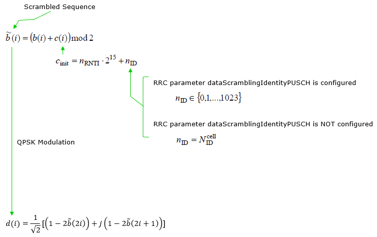
The two steps shown in the diagram are:
b̃(i) = ( b(i) + c(i) ) mod 2 with cinit = nRNTI · 215 + nID
d(i) = (1 / √2) [ ( 1 - 2 b̃(2i) ) + j ( 1 - 2 b̃(2i+1) ) ]
The first line randomizes the coded bits with a UE-specific pseudo-random sequence. The second line maps each pair of scrambled bits onto one QPSK symbol - so the number of complex symbols is exactly half the number of coded bits.
- b(i): the coded UCI bits from 38.212 clause 6.3.1, after rate matching. Not the UCI payload itself.
- c(i): the pseudo-random Gold sequence of 38.211 clause 5.2.1 (length-31 x1/x2 generators, Nc = 1600), initialized by cinit.
- cinit: the scrambling initialization. Because it contains the C-RNTI, two UEs transmitting on overlapping resources produce uncorrelated bit streams - this is what makes the scrambling UE specific rather than merely cell specific.
- nRNTI: the C-RNTI of the UE transmitting the PUCCH.
- nID: taken from RRC as shown in the diagram - dataScramblingIdentityPUSCH (0 .. 1023) when it is configured, and the physical cell ID NIDcell when it is not. In practice a captured CellGroupConfig very often configures neither this nor scramblingID0, so both the data scrambling and the DM-RS fall back to the PCI.
- b̃(i): the scrambled bits.
- d(i): the QPSK symbols, using the standard 38.211 Table 5.1.3-1 constellation - the same mapping PDSCH and PUSCH use. Format 2 has no other modulation option ; unlike Format 3/4 there is no pi/2-BPSK alternative.
- i for b(i), c(i), b̃(i): 0 to Mbit - 1, where Mbit = E = 16 · NPRB · Nsymb. The 16 comes from 8 data subcarriers per PRB (the other 4 are DM-RS) times 2 bits per QPSK symbol.
- i for d(i): 0 to Mbit/2 - 1, i.e. 8 · NPRB · Nsymb symbols.
- NPRB: 1 to 16, chosen by the UE as the smallest count that keeps the effective code rate under maxCodeRate.
- Nsymb: 1 or 2.
N_PRB = 1, N_symb = 2, C-RNTI = 0x4601 (= 17921), no dataScramblingIdentityPUSCH, PCI = 1

  n_ID    = N_ID_cell = 1
  c_init  = 17921 * 2^15 + 1 = 587235329

  M_bit   = 16 * 1 * 2 = 32 coded bits
  d(i)    = 16 QPSK symbols, i = 0 .. 15
            8 symbols in the first PUCCH symbol, 8 in the second

★ M_bit = 32 is an EXACT fit to the (32, O) Reed-Muller code block, so the
  38.212 clause 5.4.3 rate matching is the identity here - nothing is
  repeated and nothing is truncated. This is the most common PUCCH Format 2
  resource in a real configuration.
The figure covers scrambling and modulation only. Four further things are part of the Format 2 baseband sequence and are worth stating explicitly, because each of them is a place where an implementation can go wrong without producing an obviously broken signal.
- Placeholder substitution. For a 1-bit or 2-bit UCI payload, 38.212 Tables 5.3.3.1-1 and 5.3.3.2-1 emit the placeholders 'x' and 'y' rather than data bits. Clause 6.3.2.5.1 substitutes them during scrambling : if b(i) = 'x' then b̃(i) = 1, and if b(i) = 'y' then b̃(i) = b̃(i-1). Only ordinary bits go through the ( b(i) + c(i) ) mod 2 line shown in the diagram. Treating 'x' and 'y' as zeros or ones produces the wrong constellation.
- The scrambling sequence is continuous over the whole transmission. c(i) runs from i = 0 to Mbit - 1 across both OFDM symbols and, when frequency hopping is enabled, across the hop boundary. It is not restarted per symbol and not restarted per hop.
- DM-RS is generated separately and is not scrambled by this cinit. The Format 2 DM-RS is its own QPSK-mapped Gold sequence with a different initialization, and it uses scramblingID0 (else the PCI) rather than dataScramblingIdentityPUSCH :
cinitDM-RS = ( 217 · ( 14 nslot + l + 1 ) · ( 2 nID + 1 ) + 2 nID ) mod 231
Note that the OFDM symbol index l is inside it, so the two symbols of a 2-symbol resource carry different DM-RS sequences. Note also that the sequence index is an absolute subcarrier index (38.211 6.4.1.3.2.2 defines it relative to subcarrier 0 of CRB 0), so with frequency hopping the second hop's pilots are a different slice of the Gold sequence - not the first hop's pilot values moved sideways.
- RE mapping. d(i) is written into the data REs only, in increasing order of subcarrier first and OFDM symbol second, skipping the DM-RS positions at k mod 3 == 1. See Resource Element Mapping for the worked layout.
PUCCH Format 2 baseband sequence, per PRB per OFDM symbol

Subcarrier index : 0  1  2  3  4  5  6  7  8  9  10 11
Usage            : D  R  D  D  R  D  D  R  D  D  R  D

D = a d(i) from the QPSK modulation above   -> 8 per PRB per symbol
R = DM-RS, its own sequence and its own c_init at k mod 3 == 1
PUCCH Format 3 Baseband Sequence
PUCCH Format 3 is the long counterpart of Format 2. It starts from the same idea - a block of coded UCI bits is scrambled and modulated - but it differs in three structural ways, and those three differences are what the diagrams below are showing.
- It occupies 4 to 14 OFDM symbols instead of 1 or 2. That gives it far more resource elements than Format 2, so it can carry much larger UCI payloads, and far better coverage, because the receiver integrates over a much longer time.
- DM-RS occupies whole symbols instead of being frequency multiplexed. Format 2 spends 4 of every 12 subcarriers on pilots in every symbol. Format 3 instead dedicates a small number of entire OFDM symbols to DM-RS and gives all 12 subcarriers of every other symbol to data.
- It applies transform precoding, so Format 3 is DFT-s-OFDM, not CP-OFDM. This is the single most important difference from Format 2. A DFT is applied across the subcarriers of each data symbol before mapping, which restores the low-PAPR property that Format 2 gave up - and it is why Format 3 can be used at the cell edge where Format 2 cannot.
Note also what Format 3 does not have : unlike Format 1 there is no low-PAPR base sequence and no cyclic shift, and unlike Format 4 there is normally no orthogonal cover code. Format 3 is not designed for multiplexing several UEs into one PRB - it is designed to carry a large payload from one UE reliably. That role separation is why Format 3 and Format 4 share the same specification clause (38.211 6.3.2.6) but differ only at the spreading step.
The first figure covers scrambling (6.3.2.6.1) and modulation (6.3.2.6.2). As with Format 2, b(i) is not the raw UCI payload - it is already the output of the 38.212 channel coding and rate matching chain. See PUCCH Format 3 Encoding for the full chain.
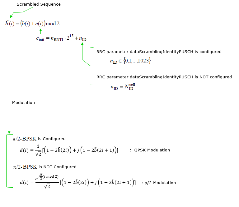

The scrambling step is identical to Format 2 - same Gold sequence, same initialization, same nID selection rule:
b̃(i) = ( b(i) + c(i) ) mod 2 with cinit = nRNTI · 215 + nID
- nRNTI is the C-RNTI, which is what makes the scrambling UE specific.
- nID is dataScramblingIdentityPUSCH (0 .. 1023) if configured, otherwise the physical cell ID NIDcell - exactly as shown in the figure.
- The sequence c(i) runs continuously from i = 0 to Mbit - 1, across all data symbols and across the frequency hop boundary. It is not restarted per symbol or per hop.
- As with Format 2, a 1-bit or 2-bit payload arrives carrying the 'x' and 'y' placeholders of 38.212 Tables 5.3.3.1-1 / 5.3.3.2-1, and clause 6.3.2.6.1 substitutes them here : if b(i) = 'x' then b̃(i) = 1, and if b(i) = 'y' then b̃(i) = b̃(i-1). Only ordinary bits take the (b(i) + c(i)) mod 2 branch drawn in the figure.
Unlike Format 2, which is QPSK only, Format 3 has two modulation options, selected by the RRC parameter pi2BPSK in PUCCH-FormatConfig. 38.211 clause 6.3.2.6.2 states the rule as : modulate "using QPSK unless pi/2-BPSK is configured".
pi2BPSK |
Modulation |
Expression |
Bits per symbol |
Msymb |
NOT configured |
QPSK (38.211 5.1.3) |
d(i) = (1/√2) [ ( 1 - 2 b̃(2i) ) + j ( 1 - 2 b̃(2i+1) ) ] |
2 |
Mbit / 2 |
Configured |
pi/2-BPSK (38.211 5.1.1) |
d(i) = ( ej(pi/2)(i mod 2) / √2 ) [ ( 1 - 2 b̃(i) ) + j ( 1 - 2 b̃(i) ) ] |
1 |
Mbit |
⚠ Two notes on the modulation box in the figure above, worth reading carefully because both are easy to copy into an implementation.
- The two branch labels are the other way round. In the figure, "pi/2-BPSK is Configured" points at the QPSK expression and "pi/2-BPSK is NOT Configured" points at the pi/2 expression. The spec rule is the opposite : QPSK is the default, and pi/2-BPSK is what you get when pi2BPSK IS configured.
- pi/2-BPSK carries ONE bit per symbol, not two. The expression in the figure applies the pi/2 rotation to a QPSK symbol built from the two bits b̃(2i) and b̃(2i+1). Real pi/2-BPSK takes a single bit b̃(i), places it on both the real and the imaginary axis, and rotates by pi/2 on every second symbol. The spec confirms this in the same clause by stating Msymb = Mbit for pi/2-BPSK against Msymb = Mbit/2 for QPSK - if pi/2-BPSK consumed two bits per symbol, those two counts would have to be equal.
The reason pi/2-BPSK exists at all is PAPR. Rotating alternate symbols by 90 degrees stops the trajectory between consecutive symbols from passing through the origin, which keeps the envelope much flatter after the DFT. It halves the payload capacity, so it is a coverage tool for power-limited UEs, not a default.
- i for b(i), c(i), b̃(i): 0 to Mbit - 1, where Mbit = 12 · NPRB · Ndata symbol · Qm. Note the 12, not the 8 of Format 2 - Format 3 uses all subcarriers of a data symbol, because its DM-RS lives in separate symbols.
- Ndata symbol = Nsymbol - NDM-RS symbol, so the DM-RS symbol positions directly determine how many bits fit.
- i for d(i): 0 to Msymb - 1, with Msymb from the table above.
The second figure shows the next step, block-wise spreading (38.211 clause 6.3.2.6.3). The important thing to notice about it is what it does not do.
Look at the equation : y( l · MscPUCCH,3 + k ) = d( l · MscPUCCH,3 + k ). The right side and the left side are the same value. For Format 3 this step is the identity - no spreading is actually applied. The current release of 38.211 states this in words rather than as an equation : "For PUCCH format 3, if interlaced mapping is not configured, no block-wise spreading is applied".
So why is the step drawn at all? Because Format 3 and Format 4 share this clause, and this is precisely where the two formats diverge : Format 4 applies a real orthogonal cover code here to multiplex several UEs into one PRB, and Format 3 passes straight through. What the equation is really doing for Format 3 is partitioning the symbol stream into per-OFDM-symbol blocks of Msc, which is the form the transform precoder needs next.
- MscPUCCH,3 = MRBPUCCH,3 · NscRB : the number of subcarriers the PUCCH occupies, i.e. the PRB count times 12. This is the block size, and it is also the DFT size in the next step.
- k = 0, 1, ..., MscPUCCH,3 - 1 : the subcarrier index inside one OFDM symbol.
- l = 0, 1, ..., (Msymb / MscPUCCH,3) - 1 : which data OFDM symbol. So Msymb / Msc is simply the number of data symbols, and the equation walks symbol by symbol.
- MRBPUCCH,3 = 2α2 · 3α3 · 5α5 : the PRB count is not free. It must factor into 2s, 3s and 5s only. The reason is the DFT in the next step - a transform of size 12 · MRB is only cheap to implement when its length has small prime factors. This is why 1, 2, 3, 4, 5, 6, 8, 9, 10, 12, 15 and 16 PRBs are allowed but 7, 11, 13 and 14 are not.
⚠ One addition from the current release : when interlaced mapping is configured (the NR-U / shared-spectrum case), Format 3 does spread - with NSF = 1 for a single interlace and NSF = 2 for two interlaces - and MRB becomes 10 or 20 rather than a 2/3/5 product. The identity shown in the figure is the normal licensed-spectrum case.
The figures stop after block-wise spreading. Two further steps of clause 6.3.2.6 complete the Format 3 baseband sequence, and the first of them is the one that defines the format.
- Transform precoding (6.3.2.6.4) - this is the missing step, and it is the reason Format 3 exists in the shape it does. A DFT of size MscPUCCH,3 is applied across the symbols of each OFDM symbol:
z( l · Msc + k ) = ( 1 / √Msc ) · Σm=0Msc-1 y( l · Msc + m ) · e-j2πmk/Msc
This makes the transmitted waveform DFT-s-OFDM (single-carrier FDMA) rather than CP-OFDM. It is the same operation PUSCH performs when transform precoding is enabled, and it is what the 2/3/5 restriction on the PRB count exists to serve.
- Mapping to physical resources (6.3.2.6.5) - the result is scaled by the amplitude factor and written into the non-DM-RS symbols, using all 12 subcarriers of each allocated PRB, in increasing order of subcarrier first and OFDM symbol second. With intra-slot frequency hopping, floor(Nsymb/2) symbols go in the first hop and the rest in the second. See Resource Element Mapping.
- DM-RS symbol placement - which symbols are removed from the data set is a function of nrofSymbols, frequency hopping and additionalDMRS, and it feeds straight back into Mbit. The table is given in PUCCH Format 3 Encoding.
PUCCH Format 3 baseband chain (38.211 clause 6.3.2.6)

UCI payload
  -> 38.212 channel coding + rate matching   -> b(i),  M_bit bits
  -> 6.3.2.6.1 scrambling                     -> b~(i)
         c_init = n_RNTI * 2^15 + n_ID
         'x' -> 1 ,  'y' -> previous scrambled bit
  -> 6.3.2.6.2 modulation                     -> d(i),  M_symb symbols
         QPSK       if pi2BPSK NOT configured   M_symb = M_bit / 2
         pi/2-BPSK  if pi2BPSK IS  configured   M_symb = M_bit
  -> 6.3.2.6.3 block-wise spreading            -> y(i)
         IDENTITY for Format 3 (non-interlaced): y(i) = d(i)
         it only partitions the stream into blocks of M_sc
  -> 6.3.2.6.4 TRANSFORM PRECODING             -> z(i)    <-- NOT IN THE FIGURES
         DFT of size M_sc = 12 * M_RB, per OFDM symbol
         this is what makes Format 3 DFT-s-OFDM
  -> 6.3.2.6.5 mapping to physical resources             <-- NOT IN THE FIGURES
         non-DM-RS symbols, all 12 subcarriers per PRB,
         k before l, then the intra-slot hop switch

M_bit = 12 * N_PRB * N_data_symbol * Q_m      Q_m = 2 (QPSK) or 1 (pi/2-BPSK)
PUCCH Format 4 Baseband Sequence
PUCCH Format 4 is Format 3 restricted to a single PRB, with block-wise spreading added so that several UEs can share that one PRB. It is specified in the same clause as Format 3 (38.211 6.3.2.6), and for good reason - scrambling, modulation, transform precoding and RE mapping are all literally the same operations. The one and only place the two formats differ is the spreading step, and that single difference is what the three figures below are built around.
The trade Format 4 makes is easy to state. Format 3 can widen to 16 PRBs when it needs capacity ; Format 4 cannot widen at all, so when it needs to serve more UEs it divides the same PRB among them using an orthogonal cover code. With occ-Length = 2 two UEs share the PRB and each gets half the data dimensions ; with occ-Length = 4 four UEs share it and each gets a quarter. Format 4 is therefore the format to reach for when many UEs each have a modest UCI payload, whereas Format 3 is for one UE with a large payload.
The first figure covers scrambling (6.3.2.6.1) and modulation (6.3.2.6.2). As with Formats 2 and 3, b(i) is the coded and rate-matched output of 38.212, not the raw UCI payload. See PUCCH Format 4 Encoding for the full chain.
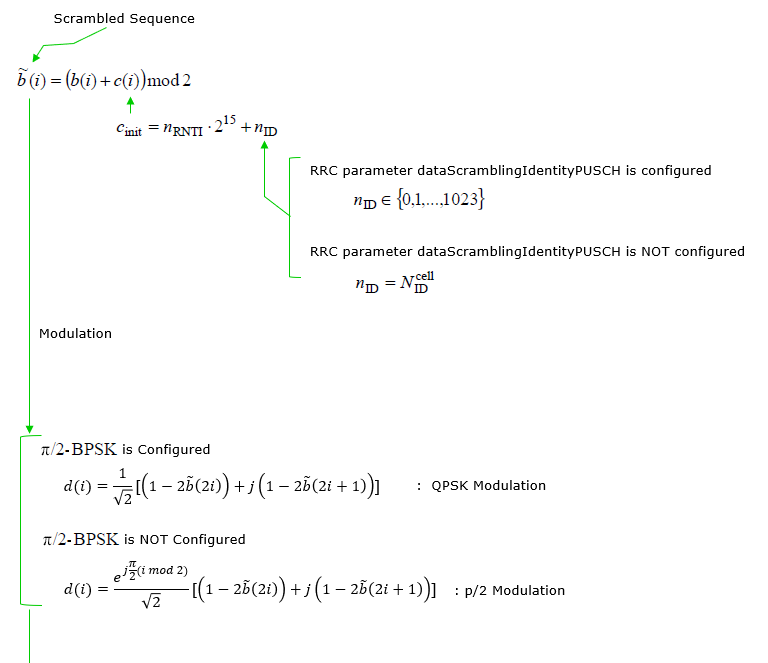

These two steps are identical to Format 3 - not merely similar, but the same clause applied to a different resource shape. Everything said in the Format 3 section applies unchanged:
- b̃(i) = ( b(i) + c(i) ) mod 2 with cinit = nRNTI · 215 + nID, where nRNTI is the C-RNTI and nID is dataScramblingIdentityPUSCH if configured, otherwise NIDcell.
- The scrambling sequence runs continuously over the whole transmission, across data symbols and across the hop boundary.
- The 'x' and 'y' UCI placeholders are substituted here : 'x' → 1, 'y' → the previous scrambled bit.
- Modulation is QPSK by default, and pi/2-BPSK when the RRC parameter pi2BPSK is configured.
⚠ The same two notes as Format 3 apply to the modulation box in the figure above, since it is the same drawing : the "pi/2-BPSK is Configured" and "NOT Configured" labels are the other way round - clause 6.3.2.6.2 says "using QPSK unless pi/2-BPSK is configured" - and real pi/2-BPSK (38.211 5.1.1) consumes one bit per symbol, d(i) = ( ej(pi/2)(i mod 2) / √2 ) [ (1 - 2b̃(i)) + j(1 - 2b̃(i)) ], giving Msymb = Mbit, not the two-bit expression drawn.
This is where Format 4 departs from Format 3. Where Format 3 passes straight through (y = d), Format 4 applies a genuine orthogonal cover code.
The expression looks intimidating, but it says something very simple. Reading it term by term:
y( l · MscPUCCH,4 + k ) = wn(k) · d( l · (MscPUCCH,4 / NSFPUCCH,4) + ( k mod (MscPUCCH,4 / NSFPUCCH,4) ) )
- MscPUCCH,4 = MRBPUCCH,4 · NscRB = 1 · 12 = 12. Because Format 4 is always one PRB, this is a constant. Note that Format 3's 2α23α35α5 restriction is irrelevant here - 1 PRB trivially satisfies it. (The figure writes this line with the superscript PUCCH,3; its own annotation "Number of RBs for PUCCH 4 = 1" shows the intent, so read it as PUCCH,4.)
- NSFPUCCH,4 ∈ {2, 4} is the spreading factor, taken directly from PUCCH-format4.occ-Length in RRC.
- k = 0, 1, ..., 11 is the subcarrier index within the PRB.
- l = 0, 1, ..., (NSF · Msymb / Msc) - 1 indexes the data OFDM symbols. Each data symbol consumes only Msc/NSF modulation symbols instead of 12, which is exactly why this count carries a factor NSF.
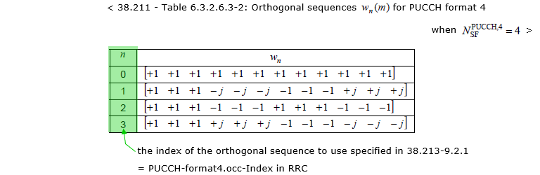
- wn(k) is the orthogonal cover code, with n taken from PUCCH-format4.occ-Index in RRC (38.213 clause 9.2.1).
The plain-language reading is : take Msc/NSF modulation symbols, repeat them NSF times to fill all 12 subcarriers, and scale each copy by one element of the cover code. The k mod (Msc/NSF) term is what produces the repetition, and wn(k) is what makes one UE's repetition pattern orthogonal to another's.
Block-wise spreading, worked out for one OFDM symbol (l = 0)

N_SF = 2  ->  M_sc/N_SF = 6 modulation symbols fill 12 subcarriers

  k       :   0     1     2     3     4     5     6     7     8     9    10    11
  d index :   0     1     2     3     4     5     0     1     2     3     4     5
  w_0(k)  :  +1    +1    +1    +1    +1    +1    +1    +1    +1    +1    +1    +1
  w_1(k)  :  +1    +1    +1    +1    +1    +1    -1    -1    -1    -1    -1    -1
                                                 ^
                                  the 2nd copy is negated for occ-Index 1

N_SF = 4  ->  M_sc/N_SF = 3 modulation symbols fill 12 subcarriers

  k       :   0     1     2  |  3     4     5  |  6     7     8  |  9    10    11
  d index :   0     1     2  |  0     1     2  |  0     1     2  |  0     1     2
  w_1(k)  :  +1    +1    +1  | -j    -j    -j  | -1    -1    -1  | +j    +j    +j
The tables of cover codes are given in 38.211 Tables 6.3.2.6.3-1 and 6.3.2.6.3-2, reproduced in the figure above for NSF = 2 and in the figure below for NSF = 4.
Three properties of those tables are worth pointing out, because together they explain why the scheme works at all.
- Each sequence is piecewise constant over blocks of Msc/NSF. For NSF = 2 the 12 entries are two runs of 6 ; for NSF = 4 they are four runs of 3. That is not a coincidence - it is the same repetition structure the formula produces, so the length-12 sequence is really an NSF-element cover code written out per subcarrier.
- The entries are the NSF-point DFT coefficients. Reading one entry per block, the rows for NSF = 4 are [1, 1, 1, 1], [1, -j, -1, +j], [1, -1, 1, -1] and [1, +j, -1, -j] - i.e. wn = e-j2πn·m/NSF. This is why complex values (±j) appear for NSF = 4 but not for NSF = 2, where the DFT degenerates to ±1.
- Any two rows are orthogonal. Summing the product of one row with the conjugate of another over the 12 subcarriers gives exactly zero. That is what lets the receiver despread : it correlates the received PRB against the cover code of the UE it wants, and every other multiplexed UE contributes nothing.
⚠ The orthogonality holds only if the channel is flat across the 12 subcarriers. The cover code is spread in frequency within a single PRB, so a frequency-selective channel across 180 kHz leaks one UE into another. At 30 kHz SCS this is normally a safe assumption, but it is the reason Format 4 is a small-cell / good-channel multiplexing tool rather than a universal one.
For Format 4:

N_data_symbol = N_symbol - N_DMRS_symbol
SF            = occ-Length   (2 or 4)

M_bit = 12 * N_data_symbol * Q_m / SF        Q_m = 2 (QPSK) or 1 (pi/2-BPSK)

If QPSK:       M_bit = 24 * N_data_symbol / SF
If pi/2-BPSK:  M_bit = 12 * N_data_symbol / SF

Per OFDM symbol, one UE gets 12/SF modulation symbols :
    SF = 2  ->  6 symbols per UE, 2 UEs share the PRB
    SF = 4  ->  3 symbols per UE, 4 UEs share the PRB
As with Format 3, the figures stop after block-wise spreading. Three further pieces complete the Format 4 baseband sequence.
- Transform precoding (6.3.2.6.4) - the missing step, applied after spreading, to the 12 spread values of each data symbol:
z( l · Msc + k ) = ( 1 / √Msc ) · Σm=0Msc-1 y( l · Msc + m ) · e-j2πmk/Msc
Format 4 is therefore DFT-s-OFDM, exactly like Format 3. Note the ordering carefully : spreading happens before the DFT, so the cover code is applied in the pre-DFT domain, not on the transmitted subcarriers.
- DM-RS is separated by the SAME occ-Index. This is easy to miss and matters for a receiver implementation : the Format 4 DM-RS sequence is selected using the orthogonal sequence index of clause 6.3.2.6.3, so the multiplexed UEs are orthogonal on their pilots as well as on their data. A channel estimator that ignores occ-Index will estimate the sum of all multiplexed UEs' channels.
- Mapping to physical resources (6.3.2.6.5) - written into the non-DM-RS symbols, all 12 subcarriers of the single PRB, in increasing order of subcarrier first and OFDM symbol second, with floor(Nsymb/2) symbols in the first hop when intra-slot frequency hopping is configured. See Resource Element Mapping.
PUCCH Format 4 baseband chain (38.211 clause 6.3.2.6)

UCI payload
  -> 38.212 channel coding + rate matching   -> b(i),  M_bit bits
  -> 6.3.2.6.1 scrambling                     -> b~(i)          same as Format 3
         c_init = n_RNTI * 2^15 + n_ID
  -> 6.3.2.6.2 modulation                     -> d(i)           same as Format 3
         QPSK, or pi/2-BPSK if pi2BPSK is configured
  -> 6.3.2.6.3 block-wise spreading            -> y(i)     <== THE ONLY DIFFERENCE
         w_n(k) from occ-Index,  SF = occ-Length in {2, 4}
         12/SF symbols repeated SF times across the PRB
  -> 6.3.2.6.4 transform precoding             -> z(i)    <-- NOT IN THE FIGURES
         DFT of size 12, per OFDM symbol  (spreading comes FIRST)
  -> 6.3.2.6.5 mapping to physical resources             <-- NOT IN THE FIGURES
         non-DM-RS symbols, 12 subcarriers of the ONE PRB,
         k before l, then the intra-slot hop switch

DM-RS is separated by the same occ-Index (38.211 6.4.1.3.3.1).
Baseband Parameters for PUCCH Format
|
RRC Parameters |
Related PUCCH Format |
Description |
|
PUCCH-F0-F1-initial-cyclic-shift |
Format 0 / 1 |
The index of the cyclic shift = {0,1,...11} |
|
PUCCH-F1-time-domain-OCC |
Format 1 |
The index of the orthogonal cover code |
|
dataScramblingIdentityPUSCH |
Format 2 / 3 / 4 |
Initialization of scrambling |
|
PUCCH-F4-preDFT-OCC-index |
Format 4 |
The index of the orthogonal cover code = {0,1,2,3} |
|
PUCCH-F4-preDFT-OCC-length |
Format 4 |
The length of the orghogonal cover code = {2,4} |
Frequeny Hopping
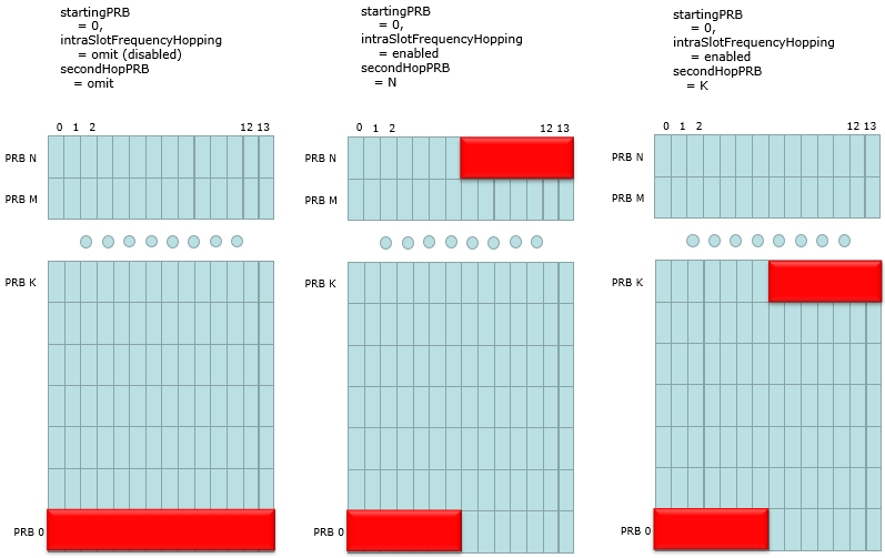
It is possible to enable or disable PUCCH using RRC Parameter PUCCH-frequency-hopping. It is configured by following Rrc parameters.
PUCCH-Resource ::= SEQUENCE {
pucch-ResourceId PUCCH-ResourceId,
startingPRB PRB-Id,
intraSlotFrequencyHopping ENUMERATED { enabled } OPTIONAL, -- Need R
secondHopPRB PRB-Id OPTIONAL, -- Need R
....
}
Followings are some of the examples of frequency hopping. For more diverse and accurate examples, refer to this note with Matlab 5G Toolbox.
Modulation
QPSK or BPSK is used depending on cases as below.
- Long PUCCH with 2 or more bits of information : QPSK
- Short PUCCH with more than 2 bits of information : QPSK
- Long PUCCH with 1 bit information : BPSK
Channel Coding
Various types of Channel coding is applied to UCI(Uplink Control Information) depending on the number of bits to be carried.
|
UCI size including CRC, if present |
Channel Code |
|
1 |
Repetition code |
|
2 |
Simplex Code |
|
3-11 |
Reed Muller Code |
|
> 11 |
Polar Code |
UCI / PUSCH Multiplexing
Is it allowed to transmit UCI and PUSCH at the same time ? This (transmition of UCI and PUSCH at the same time) is called Multiplexing and the UCI/PUSCH multiplexing is supported. This multiplexing happens in the way described as follows (38.300 - 5.3.3)
- UCI carrying HARQ-ACK feedback with 1 or 2 bits is multiplexed by puncturing PUSCH;
- In all other cases UCI is multiplexed by rate matching PUSCH.
What is PUCCH Resource and what constitues it ?
As described above, there are various parameters to define a specific PUCCH. The set of parameters for defining a specific PUCCH is called 'PUCCH Resource'. The list of parameters that are used to define a PUCCH Resource are as follows.
- startingPRB/PRB offset
- intraSlotFrequencyHopping
- secondHopPRB
- First symbol (Starting Symbol)/startingSymbolIndex
- Number of symbols/nrofSymbols
- initial CS indexes(initialCyclicShift)
- Number of PRBs/nrofPRBs
- timeDomainOCC
- occ-Length
- occ-Index
- interslotFrequencyHopping
- additionalDMRS
- maxCodeRate
- nrofSlots
- pi2BPSK
- simultaneousHARQ_ACK_CSI
Not every PUCCH format uses all of these parameters. Depending on PUCCH format, a PUCCH uses different set of parameters. Following table shows which parameter is used for which PUCCH format.
|
Parameter |
Applicable PUCCH Format |
|
starting PRB/PRB offset |
Common to All format(Format 0, Format 1, Format 2, Format 3, Format 4) |
|
intraSlotFrequencyHopping |
Common to All format(Format 0, Format 1, Format 2, Format 3, Format 4) |
|
secondHopPRB |
Common to All format(Format 0, Format 1, Format 2, Format 3, Format 4) |
|
startingSymbolIndex |
Common to All format(Format 0, Format 1, Format 2, Format 3, Format 4) |
|
nrofSymbols |
Common to All format(Format 0, Format 1, Format 2, Format 3, Format 4) |
|
initialCyclicShift |
|
|
nrofPRBs |
|
|
timeDomainOCC |
|
|
occ-Length |
|
|
occ-Index |
|
|
interslotFrequencyHopping |
Format 1, Format 2, Format 3, Format 4 (See PUCCH-FormatConfig) |
|
additionalDMRS |
Format 1, Format 2, Format 3, Format 4 (See PUCCH-FormatConfig) |
|
maxCodeRate |
Format 2, Format 3, Format 4 (See PUCCH-FormatConfig) |
|
nrofSlots |
Format 1, Format 2, Format 3, Format 4 (See PUCCH-FormatConfig) |
|
pi2BPSK |
Format 1, Format 2, Format 3, Format 4 (See PUCCH-FormatConfig) |
|
simultaneousHARQ_ACK_CSI |
Format 1, Format 2, Format 3, Format 4 (See PUCCH-FormatConfig) |
How does UE figure out which resource to apply ?
In previous section, we learned a lot of parameters are involved in defining a specific PUCCH. Then how the gNB transfer those information to UE ? In other words, how UE can figure out what kind of pucch format and parameters should be used for at the specific moment of PUCCH transmission ?
How the PUCCH Resource allocation is determined ?
There are two different ways of defining PUCCH Resource List(Table). One is to use the table predefined in 3GPP specification and the other one is to arbitrarily defined table using RRC message.
you may get a brief but nicely described big picture of PUCCH resource allocation from V-B of this paper as follows :
- The first set can only be used for a maximum of 2 HARQ-ACK bits (with a maximum of 32 PUCCH resources)
- other sets are applicable for more than 2 bits of UCI (each with a maximum of 8 PUCCH resources).
For UCI transmission including HARQ-ACK bits, a UE may be configured with up to 4 PUCCH resource sets based on the UCI size.
A UE determines the set based on the UCI size, and further indicates a PUCCH resource in the set based on a 3-bit field in DCI (complemented with an implicit rule for the first set with more than 8 resources)
This case is used in a specific case as stated below (38.213-9.2.1). It means that this table is used when there is no PUCCHResourceSet defined in PUCCH-Config in RRC. There are two RRC messages that would carry PUCCH-Config. One is RRCSetup and the other one is RRCReconfiguration in case of SA or RRCConnectionReconfiguration in case of NSA. So if PUCCH-Config is configured in RRCSetup, this table is used for only a few steps before RRCSetup message. If PUCCH-Config is not configured in RRCSetup, this table is used for pretty long time until the rrc procedure reaches RRCReconfiguration.
If a UE does not have dedicated PUCCH resource configuration, provided by higher layer parameter PUCCHResourceSet in PUCCH-Config, a PUCCH resource set is provided by higher layer parameter pucch-ResourceCommon in SystemInformationBlockType1 through an index to a row of Table 9.2.1-1 for transmission of HARQ-ACK information on PUCCH in an initial active UL BWP of N_size_BWP PRBs provided by SystemInformationBlockType1
<38.213 v15.3 - Table 9.2.1-1: PUCCH resource sets before dedicated PUCCH resource configuration >
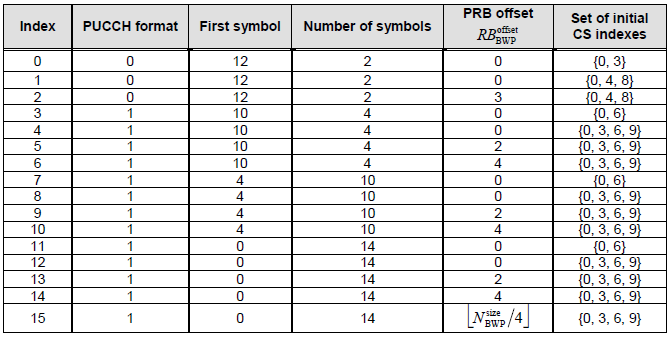
When this table is used, only one of these items (resource) can be used for a specific cell and the specific resource to be used for the cell is configured by PUCCH-ConfigCommon.pucch-ResourceCommon in SIB1 as shown below.
PUCCH-ConfigCommon ::= SEQUENCE {
pucch-ResourceCommon INTEGER (0..15) OPTIONAL, -- Need R
pucch-GroupHopping ENUMERATED { neither, enable, disable },
hoppingId INTEGER (0..1023) OPTIONAL, -- Need R
p0-nominal INTEGER (-202..24) OPTIONAL, -- Need R
...
}
As you see, pucch-ResourceCommon can specify a number between 0 and 15 which indicate the table Index in 38.213 Table 9.2.1-1.
For example, if pucch-ResourceCommon = 1. Following PUCCH configuration (resource) is used
PUCCH Format = Format 0
FirstSymbol = 12
Number of Symbols = 2
PRB Offset = 0
Set of Initial CS Indexes = {0,4,8}
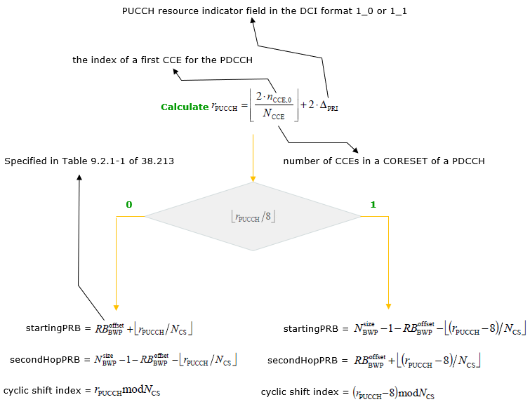
You may notice that 38.213 Table 9.2.1-1 defines the pucch format and time domain resource allocation but it does not specify the exact frequency domain resource allocation. The frequency domain resource allocation is determined by a little bit complicated algorithm as illustrated below based on 38.213-9.2.1. Simply put, the frequency domain resource is determined by DCI and PDCCH CCE location.
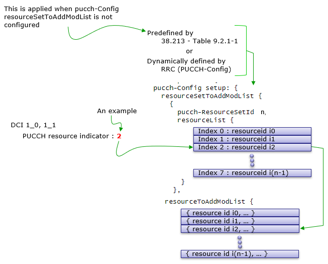
PUCCH Resource table is defined in RRC message(e.g, RRCSetup(NR), RRCReconfiguration(NR), RRCConnectionReconfiguration(LTE for NR Addition). One example of creating the PUCCH resource allocation table is shown below. Basically it has a structure and steps as follows.
Step i) : Define all the possible PUCCH Format resource a gNB would use in the IE resourceToAddModList
Step ii) : Define one or multipe Set of resources by combining the elements of resourceSetToAddModList
From the resource allocation table constructed as above, how a specific resource is picked up for UCI transmission at a specific moment. It can be determined by the two step procedure as below.
Step 1 : Select a PUCCH Resource Set from ResourceSetToAddModList based on UCI bit length
Step 2 : Select a specific resource from the resourceList within the selected resource set based on DCI
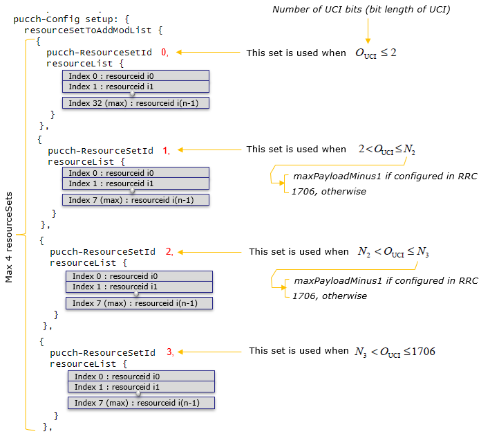
Following is an illustration showing Step 1, which is PUCCH Resource Set Selection. At this step, the UE does not yet use the DCI pucch_rsc field. The UE first counts the total number of UCI bits, OUCI, and selects one PUCCH-ResourceSet from resourceSetToAddModList. Resource set 0 is used for very small UCI payloads, i.e. OUCI <= 2. For larger UCI payloads, the next resource set is selected according to the payload thresholds configured by maxPayloadMinus1.
- PUCCH-ResourceSetId 0 : used when OUCI <= 2.
- PUCCH-ResourceSetId 1 : used when 2 < OUCI <= N2, where N2 = maxPayloadMinus1 + 1 if configured for this set, otherwise 1706.
- PUCCH-ResourceSetId 2 : used when N2 < OUCI <= N3, where N3 = maxPayloadMinus1 + 1 if configured for this set, otherwise 1706.
- PUCCH-ResourceSetId 3 : used when N3 < OUCI <= 1706.
After this resource set is selected, Step 2 uses the DCI pucch_rsc field as an index into the resourceList of the selected set.
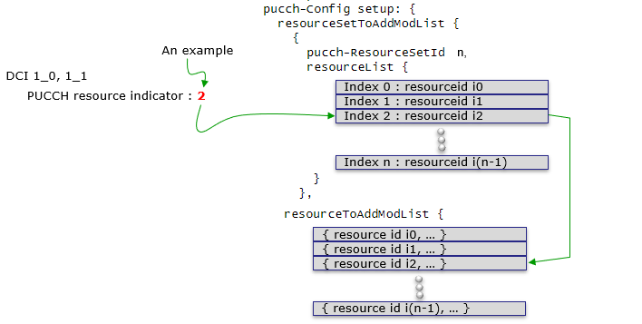
Following is an illustration showing Step 2, which is PUCCH Resource Selection within the selected resource set. At this step, the applicable PUCCH-ResourceSet has already been selected by OUCI in Step 1. The DCI field pucch_rsc, shown in the specification as PUCCH resource indicator, is then used as an index into the resourceList of that selected set. For example, if the selected set has resourceList {i0, i1, i2, ...} and the DCI indicates pucch_rsc = 2, the UE selects the third entry, resource id i2. Finally, the UE looks up that PUCCH-ResourceId in resourceToAddModList to get the actual PUCCH format, PRB, hopping, symbol and OCC configuration.
PUCCH Encoding
PUCCH encoding is what the UE does before transmission, and it is the exact mirror image of PUCCH Decoding. The UE starts from a set of UCI fields (HARQ-ACK, SR, CSI) and ends with complex values written into specific resource elements of the uplink resource grid. Everything in between - channel coding, scrambling, modulation, spreading, transform precoding and RE mapping - is fully determined by the PUCCH resource that was selected in the resource selection step.
The single most important thing to keep in mind is that PUCCH encoding is not one algorithm. Just like decoding, it splits into two completely different families.
- Format 0 / Format 1 : sequence based. The UCI value is not channel coded. It is carried by which sequence the UE transmits - a cyclic shift for Format 0, a modulated and spread sequence for Format 1. There is no scrambling and no UCI encoder in this path at all.
- Format 2 / Format 3 / Format 4 : coded bit stream. The UCI bits go through a real channel coder (Reed-Muller or Polar), rate matching, scrambling, modulation and then RE mapping. This is the conventional transmitter chain.
At high level, the transmitter side procedure is as follows.
Step |
What transmitter does |
Why it is needed |
1 |
Build the UCI payload. |
Concatenate HARQ-ACK, SR, CSI Part 1 and CSI Part 2 into a single bit sequence with a defined order and a defined length OUCI. |
2 |
Select the PUCCH resource. |
OUCI selects the PUCCH-ResourceSet, and DCI (or SR/CSI configuration) selects the resource inside it. This fixes format, PRB, symbols, hopping, cyclic shift and OCC. |
3 |
Determine the number of PRBs and the number of coded bits E. |
For Format 2/3 the UE picks the smallest PRB count that keeps the effective code rate below maxCodeRate. E then follows from PRB count, symbol count and modulation order. |
4 |
Channel code and rate match to exactly E bits. |
Only for Format 2/3/4. Format 0/1 skip this step completely. |
5 |
Scramble and modulate. |
Scrambling randomizes interference and is UE specific through the C-RNTI. Modulation is QPSK, or pi/2-BPSK for Format 3/4 when configured. |
6 |
Apply format specific spreading / precoding. |
Format 1 spreads with a cyclic-shifted base sequence and time-domain OCC. Format 4 applies block-wise spreading. Format 3/4 apply transform precoding (DFT-s-OFDM). |
7 |
Generate DM-RS. |
Every format except Format 0 transmits DM-RS so that the gNB can estimate the channel. Format 2 multiplexes DM-RS in frequency, Format 1/3/4 multiplex it in time. |
8 |
Map to resource elements and scale the amplitude. |
The final step. Data and DM-RS are written into the allocated (k, l) positions, with intra-slot frequency hopping applied if configured. |
The following table summarizes the encoding difference among the formats. Compare it with the decoding table further below - each row is simply the same row read in the opposite direction.
PUCCH Format |
Channel coding |
Modulation |
Spreading / precoding |
Scrambling |
Format 0 |
None. UCI value maps to a cyclic shift mcs. |
None. The transmitted waveform is the low-PAPR sequence. |
Cyclic shift of the length-12 base sequence. |
No |
Format 1 |
None. 1 or 2 bits modulate a single symbol d(0). |
BPSK (1 bit) or QPSK (2 bits) |
d(0) multiplies the length-12 base sequence, then time-domain OCC across data symbols. |
No |
Format 2 |
Reed-Muller (32, O) for O <= 11, Polar for O >= 12. |
QPSK only |
None. Plain CP-OFDM. |
Yes, cinit = nRNTI * 215 + nID |
Format 3 |
Reed-Muller (32, O) for O <= 11, Polar for O >= 12. |
QPSK or pi/2-BPSK |
Transform precoding (DFT-s-OFDM). |
Yes, same cinit |
Format 4 |
Reed-Muller (32, O) for O <= 11, Polar for O >= 12. |
QPSK or pi/2-BPSK |
Block-wise spreading by OCC, then transform precoding. |
Yes, same cinit |
Step 1 : UCI Payload Construction
Before anything else, the UE has to know what it is sending and how many bits it is. This is not a free choice - the gNB scheduler and the RRC configuration determine it, and both sides must arrive at the same number independently. This is exactly why PUCCH decoding cannot be done from IQ samples alone.
The fields are concatenated in a fixed order.
PUCCH UCI payload order (same order on encode and decode)

  HARQ-ACK bits
  SR bits
  CSI Part 1 bits
  CSI Part 2 bits

O_UCI = O_ACK + O_SR + O_CSI1 + O_CSI2
Two practical points here.
- A negative SR normally produces no transmission at all. For a standalone SR opportunity, "no SR" means the UE stays silent. So the SR field only appears as an explicit bit when SR is multiplexed with HARQ-ACK or CSI on Format 2/3/4.
- OUCI feeds back into resource selection. The payload size chooses the PUCCH-ResourceSet, which chooses the format, which decides whether the payload is coded at all. This is a loop that has to be resolved before encoding starts.
Step 2 : UCI Channel Coding and Rate Matching
This step applies to Format 2, 3 and 4 only. It is specified in 38.212 clause 6.3.1, and it is not a single code - it is three coding regimes plus a dispatcher that picks between them based on the payload size A = OUCI.
Payload size A |
Regime |
Spec clause |
Output block length |
A = 1 |
One-bit encoding with placeholders |
38.212 5.3.3.1, Table 5.3.3.1-1 |
Qm bits |
A = 2 |
Two-bit encoding, c0 / c1 / c2 = c0 XOR c1 |
38.212 5.3.3.2, Table 5.3.3.2-1 |
3 * Qm bits |
3 <= A <= 11 |
(32, A) Reed-Muller block code |
38.212 5.3.3.3, Table 5.3.3.3-1 |
32 bits, always |
A >= 12 |
Polar coding |
38.212 5.3.1 (+ CRC 5.1, rate matching 5.4.1) |
N = 2n, nmax = 10 so N <= 1024 |
Two further rules sit on top of the regime selection.
- CRC attachment is keyed on the whole payload A : A < 12 -> no CRC, 12 <= A < 20 -> CRC-6, A >= 20 -> CRC-11. Note the small-block regimes carry no CRC at all, which is why a Format 2 receiver has no CRC to check and must instead threshold a correlation metric.
- Code block segmentation into 2 blocks happens when (A >= 360 AND E >= 1088) OR A >= 1013. Each block is then rate matched to floor(E / C) bits.
The (32, A) Reed-Muller code is worth looking at explicitly, because it is the one that carries almost every real PUCCH Format 2 transmission - a wideband CQI is 4 bits, and CQI + PMI + RI for two ports is about 7 to 8 bits. The encoding is a simple GF(2) sum of basis columns.
Reed-Muller (32, O) encoding, 38.212 clause 5.3.3.3

  b_i = SUM over n = 0 .. O-1 of ( a_n * M_(i,n) )  mod 2      for i = 0 .. 31

  a_n   : the O information bits
  M     : the 32 x 11 basis table of Table 5.3.3.3-1
  b_i   : the 32 coded bits

In implementation this is just an XOR of the basis columns selected by the
set information bits - same arithmetic over GF(2), no multiply needed.
After the code block is produced, rate matching of clause 5.4.3 stretches or shrinks it to exactly E bits by cyclic repetition.
Small-block rate matching, 38.212 clause 5.4.3

  f(i) = b( i mod B )        for i = 0 .. E-1        B = block length

E > B : the block is repeated cyclically  (the receiver sums the repeated LLRs)
E < B : the block is truncated            (the receiver simply never observes the tail)
E = B : the identity
There is a very common case where this rate matching is the identity, and it is useful to recognize it. A Format 2 resource of 1 PRB and 2 symbols has 8 * 1 * 2 = 16 data REs, and QPSK carries 2 bits per RE, so E = 32. That is exactly the length of the Reed-Muller code block, so nothing is repeated and nothing is truncated. In other words, the smallest useful Format 2 resource is an exact fit to the (32, O) code.
One subtlety that is easy to miss : for A = 1 and A = 2, Tables 5.3.3.1-1 and 5.3.3.2-1 do not emit only 0 and 1. They emit placeholders 'x' and 'y'. These are not data bits, and a transmitter that treats them as zeros or ones will produce the wrong constellation. They are substituted later, during scrambling, by the rule in 38.211 clause 6.3.2.5.1 / 6.3.2.6.1.
Placeholder substitution during scrambling (38.211 6.3.2.5.1)

  if b(i) == 'x'  :  b~(i) = 1                 (bypass the scrambling sequence)
  if b(i) == 'y'  :  b~(i) = b~(i-1)           (repeat the previous scrambled bit)
  otherwise       :  b~(i) = ( b(i) + c(i) ) mod 2

The purpose is to maximize the Euclidean distance of the resulting
modulation symbols, not to carry information.
PUCCH Format 0 Encoding
Format 0 is the simplest format to encode and the most different in kind. There is no channel coding, no modulation symbol and no DM-RS. The information is the cyclic shift of a low-PAPR sequence. The UE does not "send bits" - it chooses which of a small set of sequences to transmit.
The encoding steps are as follows.
- Map the UCI value (HARQ-ACK bits, and/or SR state) to a cyclic shift offset mcs using the 38.213 tables.
- Compute the total cyclic shift for each PUCCH symbol : alpha = (2 * pi / 12) * ( ( m0 + mcs + ncs(ns, l) ) mod 12 ), where m0 is initialCyclicShift from the PUCCH resource and ncs is the pseudo-random cyclic-shift hopping term.
- Generate the length-12 low-PAPR base sequence ru,v(n) = ej*phi(n)*pi/4 from Table 6.3.2.2.2-2, and apply the cyclic shift : x(n) = ej*alpha*n * ru,v(n), n = 0 .. 11.
- Map the 12 values directly to the 12 subcarriers of the allocated PRB in that symbol.
- If 2 symbols are configured, repeat with the symbol-dependent ncs, and place the second symbol at secondHopPRB if intra-slot frequency hopping is enabled.
The mapping from the UCI value to mcs is the whole "encoding" of Format 0, so it is worth writing out.
Payload case |
UCI value |
mcs |
Positive SR only |
SR = positive |
0 (negative SR : transmit nothing) |
1 HARQ-ACK bit |
0 / 1 |
0 / 6 |
2 HARQ-ACK bits |
00 / 01 / 11 / 10 |
0 / 3 / 6 / 9 |
1 HARQ-ACK bit + SR |
negative SR : 0 / 1 positive SR : 0 / 1 |
negative SR : 0 / 6 positive SR : 3 / 9 |
2 HARQ-ACK bits + SR |
negative SR : 00 / 01 / 11 / 10 positive SR : 00 / 01 / 11 / 10 |
negative SR : 0 / 3 / 6 / 9 positive SR : 1 / 4 / 7 / 10 |
Notice that the cyclic shifts for each case are spread as far apart as possible around the 12 available shifts. That is deliberate - the receiver's job is a correlation contest between these candidates, so the encoder maximizes the distance between them.
Format 0 encoding summary

UCI value (HARQ-ACK / SR)
  -> select m_cs from the 38.213 table
  -> alpha = 2*pi/12 * ( m0 + m_cs + n_cs(slot, symbol) ) mod 12
  -> x(n) = exp(j*alpha*n) * r_u(n),  n = 0..11
  -> map 12 values to the 12 subcarriers of 1 PRB
  -> repeat for the 2nd symbol (at secondHopPRB if hopping)

No coding. No DM-RS. No scrambling. No modulation symbol.
PUCCH Format 1 Encoding
Format 1 is still a sequence-based format, but unlike Format 0 there is a modulation symbol. The 1 or 2 UCI bits modulate a single complex symbol d(0), and that one symbol is then spread over 12 subcarriers and over several OFDM symbols. This spreading is what gives Format 1 its coverage - the same one symbol is repeated many times, so the receiver can integrate a lot of energy.
The encoding steps are as follows.
- Modulate the UCI bits into one symbol : BPSK for 1 bit, QPSK for 2 bits. This gives d(0). For a positive SR with no HARQ-ACK, d(0) = 1 - the UE transmits the sequence itself and its presence is the information.
- Multiply the length-12 cyclic-shifted base sequence by d(0) : y(n) = d(0) * ru,v(alpha)(n), n = 0 .. 11. The cyclic shift uses the same (m0 + ncs) rule as Format 0.
- Apply the time-domain OCC across the data symbols of each hop : z(m, n) = wi(m) * y(n), where wi(m) = ej*2*pi*phi(m)/NSF comes from Table 6.3.2.4.1-2 and i = timeDomainOCC.
- Map the result to the odd PUCCH symbols (l' = 1, 3, 5, ...) of the allocation, 12 subcarriers of 1 PRB each.
- Generate the Format 1 DM-RS on the even PUCCH symbols (l' = 0, 2, 4, ...) : the same cyclic-shifted base sequence, with its own OCC.
The two properties to keep in mind here are:
- The spreading factor NSF is computed per hop, not per slot. If intra-slot frequency hopping is enabled, the allocation is split into two hops and each hop gets its own OCC length. A receiver that despreads over the whole slot instead of per hop will not close.
- Multiplexing is by (initialCyclicShift, timeDomainOCC). Several UEs, or several PUCCH resources of the same UE, can share exactly the same PRB and symbols and stay orthogonal. In a real deployment the SR resource and the Msg4 HARQ-ACK resource commonly sit on the same PRBs and are separated only by cyclic shift and OCC index.
Format 1 encoding summary

1 or 2 UCI bits
  -> BPSK / QPSK  -> one symbol d(0)
  -> y(n) = d(0) * r_u^(alpha)(n),  n = 0..11
  -> z(m,n) = w_i(m) * y(n)          time-domain OCC, N_SF per hop
  -> map to ODD PUCCH symbols, 12 subcarriers of 1 PRB
  -> DM-RS on EVEN PUCCH symbols, same base sequence + its own OCC
  -> switch PRB at the hop boundary if intra-slot hopping is on

No channel coding. No scrambling.
PUCCH Format 2 Encoding
Format 2 is the first format with a real transmitter chain, and it is the format that carries almost all periodic CSI reporting. It is short - 1 or 2 OFDM symbols - and wide - 1 to 16 PRBs - so it costs very little uplink airtime while still carrying more than 2 bits.
Before coding, the UE has to determine how many PRBs to use. This is an encode-side decision that the decoder simply has to know, and it comes from 38.213 clause 9.2.5.2 : the UE picks the smallest PRB count for which the payload still fits under the configured maxCodeRate.
Format 2 PRB count selection (38.213 9.2.5.2)

Choose the smallest N_PRB <= nrofPRBs such that

    O_UCI + O_CRC  <=  N_PRB * 8 * N_symb * Q_m * r

    8      : data subcarriers per PRB per symbol (the other 4 are DM-RS)
    N_symb : 1 or 2
    Q_m    : 2  (Format 2 is always QPSK)
    r      : maxCodeRate from PUCCH-FormatConfig
Once NPRB is fixed, the number of coded bits follows directly.
For Format 2:

Number of data RE = 8 * N_PRB * N_symbol
QPSK bits per RE  = 2
E_total           = 16 * N_PRB * N_symbol
The encoding steps are as follows.
- Build the UCI payload of OUCI bits (HARQ-ACK, SR, CSI Part 1, CSI Part 2 in that order).
- Channel code and rate match to exactly E = 16 * NPRB * Nsymbol bits, using the regime chosen by A as described above.
- Scramble the E coded bits : b~(i) = ( b(i) + c(i) ) mod 2, with the Gold sequence generated from cinit = nRNTI * 215 + nID. Here nRNTI is the C-RNTI and nID is dataScramblingIdentityPUSCH if configured, otherwise the physical cell ID.
- QPSK modulate : d(i) = ( (1 - 2*b~(2i)) + j*(1 - 2*b~(2i+1)) ) / sqrt(2). Format 2 has no other modulation option.
- Generate the DM-RS for each PUCCH symbol (see below).
- Map d(i) and the DM-RS into the resource grid, skipping the DM-RS subcarriers, in increasing order of subcarrier first and symbol second.
The DM-RS is frequency multiplexed inside every PRB - this is the defining structural feature of Format 2 and the reason it works with only 1 or 2 symbols.
PUCCH Format 2, per PRB, per OFDM symbol

Subcarrier index : 0  1  2  3  4  5  6  7  8  9  10 11
Usage            : D  R  D  D  R  D  D  R  D  D  R  D

R = DM-RS RE, at k mod 3 == 1   ->  4 pilots  per PRB per symbol
D = data RE                     ->  8 data RE per PRB per symbol

Fixed 1/3 pilot density. No OCC, no base sequence - the channel estimate is
interpolated between pilots instead.
The DM-RS sequence itself is a QPSK-mapped Gold sequence.
Format 2 DM-RS (38.211 6.4.1.3.2.1)

c_init = ( 2^17 * (14 * n_slot + l + 1) * (2 * n_ID + 1) + 2 * n_ID ) mod 2^31

r(m) = (1/sqrt(2)) * ( 1 - 2*c(2m) )  +  j * (1/sqrt(2)) * ( 1 - 2*c(2m+1) )

n_ID : scramblingID0 from DMRS-UplinkConfig if configured, else the physical cell ID
l    : the OFDM symbol index in the slot - so the two symbols of a 2-symbol
       resource use DIFFERENT sequences
There is one detail here that is very easy to get wrong, and it does not fail loudly when you do. The DM-RS index m is an absolute subcarrier index - 38.211 6.4.1.3.2.2 defines it relative to subcarrier 0 of common resource block 0, not relative to the start of the PUCCH allocation. So the sequence is conceptually generated across the whole carrier and the UE takes the slice covering its own PRBs.
The practical consequence appears as soon as intra-slot frequency hopping is enabled : because the two hops sit at different PRBs, the second hop's pilots come from a different part of the Gold sequence. They are not the first hop's pilot values moved sideways. An implementation that regenerates the sequence from index 0 for each hop produces a perfectly well-formed channel estimate built from the wrong reference, and the symptom is a receiver that detects the transmission and then decodes garbage.
PUCCH Format 3 Encoding
Format 3 is the long counterpart of Format 2. It occupies 4 to 14 symbols and 1 to 16 PRBs, so it has far more resource elements and can carry much larger UCI payloads. The important structural differences from Format 2 are that DM-RS occupies whole symbols instead of being frequency multiplexed, and that transform precoding is applied - Format 3 is DFT-s-OFDM, not CP-OFDM.
The encoding steps are as follows.
- Build the UCI payload and determine NPRB the same way as Format 2, using maxCodeRate. ⚠ For Format 3 the PRB count is additionally restricted to values of the form 2a1 * 3a2 * 5a3, because the DFT size must be factorizable.
- Channel code and rate match to E bits.
- Scramble with the same cinit = nRNTI * 215 + nID.
- Modulate as QPSK, or pi/2-BPSK when pi2BPSK is configured.
- Apply transform precoding : a DFT of size 12 * NPRB over the modulation symbols of each data OFDM symbol. This is what keeps the PAPR low.
- Map to the non-DM-RS symbols, using all 12 subcarriers of each allocated PRB.
- Generate Format 3 DM-RS on the DM-RS symbol positions.
The number of coded bits depends on how many symbols are left after the DM-RS symbols are taken out.
For Format 3:

N_data_symbol = N_symbol - N_DMRS_symbol

If QPSK:
  E_total = 24 * N_PRB * N_data_symbol

If pi/2-BPSK:
  E_total = 12 * N_PRB * N_data_symbol
Which symbols are DM-RS depends on nrofSymbols, frequency hopping and additionalDMRS. The encoder uses exactly the same table the decoder uses.
nrofSymbols |
DM-RS symbol positions inside the PUCCH allocation |
4 |
Without hopping : symbol 1. With hopping : symbols 0 and 2. |
5 |
symbols 0 and 3 |
6 or 7 |
symbols 1 and 4 |
8 |
symbols 1 and 5 |
9 |
symbols 1 and 6 |
10 to 14 |
Normally 2 DM-RS symbols. If additionalDMRS is enabled, 4 DM-RS symbols are used. |
PUCCH Format 4 Encoding
Format 4 is Format 3 restricted to a single PRB, with block-wise spreading added so that several UEs can share that one PRB. Everything up to modulation is identical to Format 3. The extra step is the OCC spreading, and it is applied before transform precoding.
The encoding steps are as follows.
- Build the UCI payload, channel code and rate match to E bits.
- Scramble with the same cinit = nRNTI * 215 + nID.
- Modulate as QPSK or pi/2-BPSK.
- Block-wise spread using the OCC selected by occ-Length (the spreading factor, SF = 2 or 4) and occ-Index. Each modulation symbol is spread into SF values, so 12/SF independent symbols fill each PRB symbol.
- Apply transform precoding over the 12 spread values of each data symbol.
- Map to the non-DM-RS symbols, 12 subcarriers of the single PRB.
- Generate Format 4 DM-RS - the estimator on the far side also needs occ-Index, because OCC affects the reference structure.
Because SF values are spent carrying one modulation symbol, the payload capacity is divided by the spreading factor.
For Format 4:

N_data_symbol = N_symbol - N_DMRS_symbol
SF            = occ-Length   (2 or 4)

If QPSK:
  E_total = 24 * N_data_symbol / SF

If pi/2-BPSK:
  E_total = 12 * N_data_symbol / SF
This is the trade that Format 4 makes explicit : the PRB is shared by SF UEs, and each of them gets 1/SF of the data dimensions.
Resource Element Mapping
RE mapping is the last step of encoding and it is where all the earlier configuration finally becomes a physical position in the grid. It is worth treating as a first-class step rather than as an afterthought, because a mapping error does not produce an obviously broken signal - it produces a signal with the right energy in roughly the right place that simply does not decode.
The general rule for all PUCCH formats is the same.
PUCCH RE mapping, general rule

1. Take the allocated region : PRBs from startingPRB, symbols from
   startingSymbolIndex for nrofSymbols.

2. Write the sequence into REs (k, l) in the allocated region in
   INCREASING ORDER OF k FIRST, THEN l.
   i.e. fill an entire OFDM symbol across all allocated PRBs,
        then move to the next OFDM symbol.

3. SKIP the REs that are reserved for DM-RS in that format.

4. If intraSlotFrequencyHopping is configured, switch from startingPRB
   to secondHopPRB at the hop boundary.

5. Scale by the amplitude factor beta_PUCCH and transmit on the single
   antenna port p = 2000.
The per-format RE usage is summarized below. This is the table to check first whenever a PUCCH does not decode.
Format |
PRBs |
Symbols |
Where DM-RS lives |
Data REs |
Format 0 |
1 |
1 or 2 |
None - there is no DM-RS. |
All 12 subcarriers carry the cyclic-shifted sequence. |
Format 1 |
1 |
4 to 14 |
In TIME : the even PUCCH symbols (l' = 0, 2, 4, ...). |
12 subcarriers on each odd PUCCH symbol. |
Format 2 |
1 to 16 |
1 or 2 |
In FREQUENCY : subcarriers with k mod 3 == 1, in every symbol. |
8 per PRB per symbol. |
Format 3 |
1 to 16 (2a13a25a3) |
4 to 14 |
In TIME : whole symbols, positions from the nrofSymbols table. |
All 12 subcarriers per PRB on each data symbol. |
Format 4 |
1 |
4 to 14 |
In TIME : whole symbols, same table as Format 3. |
12 subcarriers per data symbol, carrying 12/SF spread symbols. |
A concrete Format 2 example makes the "k first, then l" ordering unambiguous. Take NPRB = 2, Nsymb = 2, startingPRB = 0, no hopping. That gives E = 16 * 2 * 2 = 64 coded bits, i.e. 32 QPSK symbols d(0) .. d(31).
Format 2 RE mapping, N_PRB = 2, N_symb = 2, startingPRB = 0

symbol l0    PRB 0   k    :  0  1  2  3  4  5  6  7  8  9 10 11
                     d(i) :  0  R  1  2  R  3  4  R  5  6  R  7
             PRB 1   k    : 12 13 14 15 16 17 18 19 20 21 22 23
                     d(i) :  8  R  9 10  R 11 12  R 13 14  R 15

symbol l0+1  PRB 0   d(i) : 16  R 17 18  R 19 20  R 21 22  R 23
             PRB 1   d(i) : 24  R 25 26  R 27 28  R 29 30  R 31

R = DM-RS RE.  The symbol index advances only after BOTH PRBs of the
current symbol have been filled.
Now the same resource with intra-slot frequency hopping enabled, startingPRB = 49 and secondHopPRB = 1, with 1 PRB and 2 symbols. With 2 symbols there is exactly one symbol per hop.
Format 2 with hopping, N_PRB = 1, N_symb = 2, startingPRB = 49, secondHopPRB = 1

hop 0 = symbol l0    at PRB 49  : d(0)..d(7)   + 4 DM-RS
hop 1 = symbol l0+1  at PRB 1   : d(8)..d(15)  + 4 DM-RS

E = 16 * 1 * 2 = 32 coded bits -> an exact fit to the (32, O) Reed-Muller block.

⚠ Half of the data REs are at the OTHER END OF THE BAND. A receiver that
  ignores secondHopPRB still sees the first hop's DM-RS - so it still
  DETECTS the transmission - but it harvests half of its data REs from
  noise and decodes a wrong payload with high confidence.

⚠ The DM-RS of hop 1 is generated at absolute subcarrier index 1*4 = 4,
  not at 49*4 = 196. It is a different slice of the Gold sequence, not the
  same pilot values moved to a different PRB.
Two more mapping rules that are frequently overlooked:
- Scrambling runs across the whole transmission, not per symbol. The Gold sequence index continues from one OFDM symbol to the next, and across the hop boundary. Restarting it at each symbol or each hop produces a valid-looking but undecodable signal.
- The hop split rule is format dependent. 38.211 6.3.2.1 defines the floor(Nsymb/2) split for Formats 1, 3 and 4. For Format 2, hopping is only defined for the 2-symbol case, one symbol per hop; a 1-symbol Format 2 resource with hopping is not something the spec text establishes, and inventing a split there is a good way to produce a silent wrong answer.
What the Encoder and Decoder Must Agree On
Because PUCCH carries no CRC in the small-payload regimes and no explicit format indicator anywhere, the receiver cannot discover any of the encoding parameters from the signal. Every one of them has to be derived independently on both sides from RRC, DCI and the scheduler state. If any single item below differs between the two ends, the result is almost never a clean failure - it is a plausible wrong answer.
Parameter |
Where it comes from |
What happens if the two sides disagree |
Format, PRB, symbols |
PUCCH-Config resource, or 38.213 Table 9.2.1-1 before dedicated config |
The receiver reads the wrong REs. With Format 2 it may still see DM-RS energy and report a detection. |
secondHopPRB / hopping enable |
PUCCH-Config resource |
Half the data REs are taken from noise. Detection succeeds, decoding does not. |
OUCI (each field's bit count) |
Scheduler, CSI report config, HARQ codebook |
The wrong coding regime is selected, so the decoder correlates against the wrong codebook. |
nRNTI and nID (scrambling) |
C-RNTI; dataScramblingIdentityPUSCH else physical cell ID |
Descrambling produces noise. The correlation decoder still returns its best candidate. |
nID for DM-RS |
scramblingID0 else physical cell ID |
The channel estimate is well formed but built from the wrong reference - magnitude looks healthy, phase is useless. |
initialCyclicShift / OCC index |
PUCCH-Config resource |
Another UE's or another resource's transmission can be attributed to this one. |
maxCodeRate |
PUCCH-FormatConfig |
The two sides compute a different NPRB, so the resource sizes do not even match. |
So the most practical way to read PUCCH encoding is the mirror of the decoding checklist :
- First fix the payload : which UCI fields, how many bits, in which order.
- Then fix the resource : format, PRB count, symbols, hopping, OCC, cyclic shift - remembering that for Format 2/3 the PRB count is derived from the payload and maxCodeRate, not simply configured.
- Then choose the encoding path : a cyclic shift or a spread sequence for Format 0/1, a full coded chain for Format 2/3/4.
- Finally map to REs : k before l, skip the DM-RS positions, switch PRB at the hop boundary, and keep the scrambling sequence running across the whole transmission.
PUCCH Decoding
PUCCH decoding is not the same for all PUCCH formats. The receiver first has to know which PUCCH resource is expected. This information comes from RRC, DCI, SR/CSI configuration and scheduler decision. Once the receiver knows the format, PRB, symbol location, hopping, scrambling ID and expected UCI payload size, it can process the received resource grid.
At high level, the receiver side procedure is as follows.
Step |
What receiver does |
Why it is needed |
1 |
Determine the expected PUCCH resource. |
The receiver should know format, PRB, symbol allocation, hopping, cyclic shift, OCC and expected UCI size. |
2 |
Extract the corresponding REs from the uplink resource grid. |
PUCCH occupies only a small part of the slot, so the receiver first cuts out the expected REs. |
3 |
Apply format-specific detection or demodulation. |
Format 0/1 are sequence based. Format 2/3/4 are data-symbol based and produce soft bits. |
4 |
Recover UCI fields. |
The final output is HARQ-ACK, SR, CSI Part 1 and/or CSI Part 2, with a valid/invalid status. |
From implementation point of view, the source tree in RAN protocol stack separates the receiver into two different paths. This is a very useful way to understand PUCCH decoding.
- Format 0 / Format 1 : handled by a detector. The receiver tests candidate sequences and decides which UCI value was most likely transmitted.
- Format 2 / Format 3 / Format 4 : handled by channel estimation + equalization + demodulation + UCI decoding. The receiver produces LLRs and then decodes UCI bits.
The following table summarizes the decoding difference among the formats.
PUCCH Format |
Typical UCI size |
Resource style |
Receiver method |
Format 0 |
1 or 2 HARQ-ACK bits, and/or SR |
Short PUCCH, 1 PRB, 1 or 2 symbols |
Correlate candidate low-PAPR sequences and map selected cyclic shift to UCI. |
Format 1 |
1 or 2 HARQ-ACK bits, and/or SR |
Long PUCCH, 1 PRB, 4 to 14 symbols, OCC supported |
Use DM-RS/data symbol relation, cyclic shift and time-domain OCC to detect the transmitted symbol. |
Format 2 |
More than 2 UCI bits |
Short PUCCH, 1 or 2 symbols, 1 to 16 PRBs |
Estimate channel from frequency-multiplexed DM-RS, equalize data REs, QPSK demodulate and decode UCI. |
Format 3 |
More than 2 UCI bits |
Long PUCCH, 4 to 14 symbols, 1 to 16 PRBs |
Use DM-RS symbols for channel estimation, equalize data symbols, reverse transform precoding, demodulate and decode UCI. |
Format 4 |
More than 2 UCI bits |
Long PUCCH, 4 to 14 symbols, 1 PRB, OCC supported |
Same general path as Format 3, but also undo OCC/block-wise spreading before demodulation. |
PUCCH Format 0 Decoding
PUCCH Format 0 is the shortest PUCCH format. It uses 1 PRB and 1 or 2 OFDM symbols. It does not carry a coded bit stream in the same way as PUCCH format 2/3/4. Instead, the UCI value is represented by a cyclic shift of a low-PAPR sequence. So the receiver does not start from soft-bit demodulation. It starts from sequence detection.
The receiver needs the following information before decoding Format 0.
Parameter |
Meaning |
startingPRB / secondHopPRB |
Where the 1 PRB PUCCH is located in the first hop and optionally in the second hop. |
startingSymbolIndex / nrofSymbols |
Which 1 or 2 symbols contain the PUCCH. |
initialCyclicShift |
Base cyclic shift configured for the PUCCH resource. |
nID / hopping ID |
Used to generate the low-PAPR base sequence and cyclic shift. |
nof_harq_ack and SR opportunity |
Tells the receiver which candidate UCI table should be tested. |
The decoding flow is as follows.
- Extract 12 REs per configured PUCCH symbol and per Rx antenna port. Since Format 0 uses 1 or 2 symbols, the total is 12 * nrofSymbols REs per Rx port, i.e. 12 REs for 1 symbol or 24 REs for 2 symbols.
- If intra-slot frequency hopping is configured, use startingPRB for the first hop and secondHopPRB for the second hop.
- Build the candidate cyclic-shift table according to expected HARQ/SR payload.
- For each candidate, generate the corresponding low-PAPR sequence using group sequence, slot, symbol, nID, initial cyclic shift and candidate mcs.
- Correlate the received 12 REs of each PUCCH symbol with the candidate low-PAPR sequence for that symbol.
- Accumulate correlation power and noise estimate over symbols and Rx ports.
- Select the candidate with the largest detection metric.
- If the metric is above threshold, declare the UCI valid. Otherwise, declare it invalid.
The important decoding table for Format 0 is the mapping between mcs and UCI value. For example, from the implementation view, the receiver tests candidate tables like this.
Expected payload |
Candidate cyclic shifts |
Interpretation |
Positive SR only |
mcs = 0 |
Detected sequence means positive SR. |
1 HARQ-ACK bit, no SR |
mcs = 0, 6 |
mcs 0 means ACK bit 0. mcs 6 means ACK bit 1. |
2 HARQ-ACK bits, no SR |
mcs = 0, 3, 6, 9 |
These represent 00, 01, 11, 10 respectively. |
HARQ-ACK plus SR opportunity |
More candidate cyclic shifts are tested. |
The selected sequence jointly indicates HARQ-ACK bits and whether SR is positive or negative. |
In short, Format 0 decoding is mostly a best sequence search. There is no separate DM-RS based channel estimation step and no UCI decoder step like polar/short-block decoding. The receiver asks : "Among all legal sequences for this expected HARQ/SR case, which one matches the received signal best ?"
Format 0 decoding summary

RRC/DCI/SR context
  -> expected PRB/symbol/initial cyclic shift/nID
  -> expected HARQ/SR payload case
  -> generate candidate low-PAPR sequences
  -> correlate 12 REs per PUCCH symbol with each candidate sequence
  -> accumulate metric over 1 or 2 symbols and Rx ports
  -> pick best metric
  -> map selected cyclic shift to SR/HARQ-ACK bits
PUCCH Format 1 Decoding
PUCCH Format 1 is also used for small UCI payload, but it is a long PUCCH format. It uses 1 PRB and 4 to 14 symbols. It can use time-domain OCC and initial cyclic shift, so multiple UEs or multiple PUCCH candidates may be separated on the same time/frequency resource.
Unlike Format 0, Format 1 has a more explicit separation between DM-RS-like symbols and UCI carrying symbols. In practical receiver implementation, Format 1 is still treated as a detector, not as a normal UCI codeword demodulator.
The receiver needs the following information.
Parameter |
Meaning |
startingPRB / secondHopPRB |
First-hop and optional second-hop PRB. |
startingSymbolIndex / nrofSymbols |
Long PUCCH symbol allocation. Format 1 uses 4 to 14 symbols. |
initialCyclicShift |
Frequency-domain sequence separation. |
timeDomainOCC |
Time-domain orthogonal cover code index. |
nID / hopping ID |
Used for low-PAPR sequence generation. |
Expected number of HARQ-ACK bits |
Determines whether the detector decides BPSK-like 1 bit or QPSK-like 2 bits. SR-only is a special small-payload case. |
The decoding flow is roughly as follows.
- Group all Format 1 PUCCH candidates that share the same PRB/symbol allocation.
- For each candidate, keep the pair (initialCyclicShift, timeDomainOCC) and the expected number of HARQ-ACK bits.
- Separate the allocated symbols into reference-symbol positions and data-symbol positions. In a typical long Format 1 receiver, every other allocated symbol starting from the first one is treated as DM-RS/reference side.
- For each hop, despread the received symbols using the configured OCC and cyclic shift.
- Estimate the channel from the reference side. A practical implementation may discard very weak cyclic-shift paths, for example paths more than 10 dB below the strongest one.
- Estimate noise by comparing received and reconstructed reference signal.
- Form the cross term between data and reference components.
- Detect the most likely BPSK/QPSK symbol and map it to HARQ-ACK bits.
- Compare the detection metric with a threshold. If the metric is too low, mark UCI as invalid.
The most important difference from Format 0 is that Format 1 detection uses the relationship between the reference part and the data part across several OFDM symbols. It is not simply checking one cyclic-shift table. The receiver uses the configured OCC to combine symbols and then decides the transmitted UCI symbol.
Format 1 decoding summary

RRC/DCI/SR context
  -> expected PRB/symbol/initial cyclic shift/OCC/nID
  -> extract long PUCCH resource
  -> separate reference symbols and data symbols
  -> combine symbols using time-domain OCC
  -> estimate channel and noise
  -> detect BPSK/QPSK symbol
  -> recover HARQ-ACK and/or positive SR state
One thing to be careful about is SR. A standalone negative SR normally does not create a PUCCH transmission. If a Format 1 PUCCH is detected, it usually means the receiver expected a positive SR or HARQ-ACK related PUCCH. When HARQ-ACK and SR are multiplexed, the selected resource/sequence tells whether SR is positive or not according to the multiplexing rule.
PUCCH Format 2 Decoding
PUCCH Format 2 is a short PUCCH format for more than 2 UCI bits. It uses 1 or 2 symbols and can occupy multiple PRBs. Unlike Format 0/1, Format 2 carries a coded UCI bit stream. Therefore, the receiver follows a more conventional demodulation path : channel estimation, equalization, soft demodulation, descrambling and UCI decoding.
Format 2 has DM-RS frequency-multiplexed with data inside each PRB. In the implementation I checked, the data subcarriers in each PRB are selected as follows.
PUCCH Format 2, per PRB

Subcarrier index : 0  1  2  3  4  5  6  7  8  9  10 11
Usage            : D  R  D  D  R  D  D  R  D  D  R  D

D = data RE
R = DM-RS RE

So there are 8 data subcarriers per PRB per OFDM symbol.
The decoding flow is as follows.
- Build a UCI message container with expected bit lengths : HARQ-ACK, SR, CSI Part 1 and CSI Part 2.
- Configure the DM-RS estimator using slot, cyclic prefix, start symbol, number of symbols, PRB allocation, nID0 and Rx ports.
- Estimate the channel from Format 2 DM-RS REs.
- Extract only the data REs from the resource grid. In every PRB, the receiver skips the DM-RS REs and keeps 8 data REs.
- Extract matching channel estimates for those data REs.
- Equalize the data REs using the channel estimates and noise variance.
- Soft-demodulate equalized symbols as QPSK. Format 2 modulation is QPSK.
- Descramble the LLR sequence using cinit = RNTI * 215 + nID.
- Run the UCI decoder to recover HARQ-ACK/SR/CSI bits.
The number of soft bits before UCI decoding is determined by the number of PRBs and symbols.
For Format 2:

Number of data RE = 8 * N_PRB * N_symbol
QPSK bits per RE  = 2
E_total           = 16 * N_PRB * N_symbol
So Format 2 decoding is not a sequence selection problem. It is a short coded-UCI receiver. If the expected UCI payload is, for example, HARQ-ACK + SR + CSI Part 1, the decoder fills the final payload in the order used by UCI mapping : HARQ-ACK first, then SR, then CSI Part 1, then CSI Part 2.
PUCCH Format 3 Decoding
PUCCH Format 3 is a long PUCCH format for more than 2 UCI bits. It can occupy 1 to 16 PRBs and 4 to 14 symbols. It is useful for larger UCI payloads because it has more resource elements than Format 2. It also uses transform precoding, so the receiver has to reverse transform precoding before UCI decoding.
For Format 3, DM-RS is not frequency-multiplexed with data in every symbol like Format 2. Instead, some OFDM symbols are DM-RS symbols and the remaining symbols carry data. Which symbols are DM-RS depends on nrofSymbols, frequency hopping and additionalDMRS.
A practical DM-RS symbol selection rule can be summarized as follows.
nrofSymbols |
DM-RS symbol positions inside the PUCCH allocation |
4 |
Without hopping : symbol 1. With hopping : symbols 0 and 2. |
5 |
symbols 0 and 3 |
6 or 7 |
symbols 1 and 4 |
8 |
symbols 1 and 5 |
9 |
symbols 1 and 6 |
10 to 14 |
Normally 2 DM-RS symbols. If additionalDMRS is enabled, 4 DM-RS symbols are used. |
The decoding flow is as follows.
- Build the expected UCI message container : number of HARQ-ACK bits, SR bits, CSI Part 1 bits and CSI Part 2 bits.
- Estimate the channel using the Format 3 DM-RS symbols. The estimator uses slot, PRB allocation, hopping, nID for hopping/scrambling and Rx ports.
- Build a DM-RS symbol mask. The receiver skips those symbols when extracting data.
- Extract all data REs from the non-DM-RS symbols. Format 3 uses all 12 subcarriers of each data symbol in each allocated PRB.
- If intra-slot hopping is enabled, switch from first PRB allocation to second-hop PRB allocation at the second half of the PUCCH symbols.
- Equalize the data REs using the channel estimates.
- Reverse transform precoding symbol by symbol.
- Soft-demodulate as QPSK or pi/2-BPSK depending on configuration.
- Descramble the LLR sequence using cinit = RNTI * 215 + nID.
- Run UCI decoder and check that the decoded payload length matches the expected UCI length.
The soft-bit length can be estimated as follows.
For Format 3:

N_data_symbol = N_symbol - N_DMRS_symbol

If QPSK:
  E_total = 24 * N_PRB * N_data_symbol

If pi/2-BPSK:
  E_total = 12 * N_PRB * N_data_symbol
In short, Format 3 decoding is a long-PUCCH coded-UCI receiver. The most important format-specific points are DM-RS symbol masking, transform precoding reversal and the QPSK/pi/2-BPSK choice.
PUCCH Format 4 Decoding
PUCCH Format 4 is also a long PUCCH format for more than 2 UCI bits, but it is designed for UE multiplexing within a single PRB. It uses 4 to 14 symbols and only 1 PRB. Multiplexing is done by OCC, using occ-Length and occ-Index.
Format 4 decoding is very close to Format 3 decoding until equalization. The key additional step is inverse block-wise spreading. The receiver first equalizes the spread REs, then uses the configured OCC sequence to recover the original data symbols before soft demodulation.
The receiver needs the following Format 4 specific parameters.
Parameter |
Meaning |
startingPRB / secondHopPRB |
One PRB for first hop and optional second hop. |
nrofSymbols / startingSymbolIndex |
Long PUCCH time allocation, 4 to 14 symbols. |
occ-Length |
Spreading factor. This reduces the number of independent data symbols by the spreading factor. |
occ-Index |
Selects the OCC sequence used to separate this UE/resource from others. |
additionalDMRS |
Controls whether additional DM-RS symbols are used for long allocations. |
pi2BPSK |
Selects pi/2-BPSK instead of QPSK when configured. |
The decoding flow is as follows.
- Build the expected UCI message container with HARQ-ACK/SR/CSI bit lengths.
- Estimate the channel using Format 4 DM-RS. The estimator also needs occ-Index because OCC affects the reference/data structure for this multiplexed format.
- Build the same kind of DM-RS symbol mask used for Format 3/4.
- Extract data REs from non-DM-RS symbols. Format 4 uses one PRB, so there are 12 REs per data symbol before despreading.
- Equalize the received REs and reverse transform precoding.
- Apply inverse block-wise spreading using the OCC sequence selected by occ-Length and occ-Index.
- Soft-demodulate the despread symbols as QPSK or pi/2-BPSK.
- Descramble LLRs using cinit = RNTI * 215 + nID.
- Run the UCI decoder and split the result into HARQ-ACK, SR, CSI Part 1 and CSI Part 2.
The soft-bit length after despreading can be estimated as follows.
For Format 4:

N_data_symbol = N_symbol - N_DMRS_symbol
SF            = occ-Length

If QPSK:
  E_total = 24 * N_data_symbol / SF

If pi/2-BPSK:
  E_total = 12 * N_data_symbol / SF
This is why Format 4 is good for multiplexing. Several UEs can share the same PRB/symbol region with different OCC indexes, but each UE gets only a fraction of the available data dimensions depending on the OCC length.
UCI Output after PUCCH Decoding
After decoding or detection, the final output is not just a raw bit string. The receiver interprets the bit string as UCI fields. In the source code view, the PUCCH UCI message is arranged as follows.
PUCCH UCI payload order

HARQ-ACK bits
SR bits
CSI Part 1 bits
CSI Part 2 bits
The number of bits in each field must be known before decoding. This is why PUCCH decoding cannot be done from IQ samples alone. The receiver needs the scheduling context : how many HARQ-ACK bits are expected, whether SR is considered, whether CSI is expected, which PUCCH format/resource is used and which scrambling/sequence IDs apply.
For Format 0/1, the result is usually a detected UCI message plus a detection metric and channel quality information. For Format 2/3/4, the receiver produces LLRs, decodes UCI, and then checks that the decoded payload length equals the expected number of UCI bits.
So the most practical way to read PUCCH decoding is as follows.
- First identify the resource : format, PRB, symbols, hopping, OCC, cyclic shift.
- Then identify expected UCI size : HARQ-ACK bits, SR bits, CSI Part 1 and CSI Part 2 bits.
- Then choose decoding path : sequence detector for Format 0/1, coded-UCI demodulator/decoder for Format 2/3/4.
- Finally interpret output : valid/invalid status, HARQ-ACK, SR and CSI fields.
Examples
The examples in this section show how a PUCCH resource is configured in RRC and then referenced/applied by DCI. The important point is that DCI pucch_rsc does not directly index the whole resourceToAddModList. The UE first selects a PUCCH-ResourceSet based on the UCI payload size OUCI, and then interprets pucch_rsc as an index into the resourceList of that selected resource set. The value obtained from that resource list is the PUCCH-ResourceId, and the actual PRB/symbol/OCC definition is found in resourceToAddModList.
Example 1 : Use of PUCCH resource set 0 for a Small UCI payload
This example shows the complete chain from PUCCH resource definition to actual PUCCH transmission. The RRCSetup message configures a list of PUCCH resources. Later, a DL DCI indicates pucch_rsc=0 for HARQ-ACK feedback. The UE then transmits PUCCH using the corresponding configured resource.
In the RRCSetup message, resourceSetToAddModList defines the available PUCCH resource sets and resourceToAddModList defines the actual PUCCH resources. In this example, PUCCH-ResourceSetId 0 contains resource IDs 0 through 7. PUCCH-ResourceId 0 is a format 1 resource using PRB 50 in the first hop and PRB 0 in the second hop.
20:10:28.594 [RRC] DL 0001 00 CCCH-NR: RRC setup
{
  message c1: rrcSetup: {
    ...
    spCellConfig {
      spCellConfigDedicated {
        uplinkConfig {
          initialUplinkBWP {
            pucch-Config setup: {
              resourceSetToAddModList {
                {
                  pucch-ResourceSetId 0,
                  resourceList {
                    0,
                    1,
                    2,
                    3,
                    4,
                    5,
                    6,
                    7
                  }
                },
                {
                  pucch-ResourceSetId 1,
                  resourceList {
                    8,
                    9,
                    10,
                    11
                  }
                }
              },
              resourceToAddModList {
                {
                  pucch-ResourceId 0,
                  startingPRB 50,
                  intraSlotFrequencyHopping enabled,
                  secondHopPRB 0,
                  format format1: {
                    initialCyclicShift 1,
                    nrofSymbols 14,
                    startingSymbolIndex 0,
                    timeDomainOCC 0
                  }
                },
                {
                  pucch-ResourceId 1,
                  startingPRB 50,
                  intraSlotFrequencyHopping enabled,
                  secondHopPRB 0,
                  format format1: {
                    initialCyclicShift 5,
                    nrofSymbols 14,
                    startingSymbolIndex 0,
                    timeDomainOCC 0
                  }
                },
                {
                  pucch-ResourceId 2,
                  startingPRB 50,
                  intraSlotFrequencyHopping enabled,
                  secondHopPRB 0,
                  format format1: {
                    initialCyclicShift 9,
                    nrofSymbols 14,
                    startingSymbolIndex 0,
                    timeDomainOCC 0
                  }
                },
                {
                  pucch-ResourceId 3,
                  startingPRB 50,
                  intraSlotFrequencyHopping enabled,
                  secondHopPRB 0,
                  format format1: {
                    initialCyclicShift 1,
                    nrofSymbols 14,
                    startingSymbolIndex 0,
                    timeDomainOCC 1
                  }
                },
                {
                  pucch-ResourceId 4,
                  startingPRB 50,
                  intraSlotFrequencyHopping enabled,
                  secondHopPRB 0,
                  format format1: {
                    initialCyclicShift 5,
                    nrofSymbols 14,
                    startingSymbolIndex 0,
                    timeDomainOCC 1
                  }
                },
                {
                  pucch-ResourceId 5,
                  startingPRB 50,
                  intraSlotFrequencyHopping enabled,
                  secondHopPRB 0,
                  format format1: {
                    initialCyclicShift 9,
                    nrofSymbols 14,
                    startingSymbolIndex 0,
                    timeDomainOCC 1
                  }
                },
                {
                  pucch-ResourceId 6,
                  startingPRB 50,
                  intraSlotFrequencyHopping enabled,
                  secondHopPRB 0,
                  format format1: {
                    initialCyclicShift 1,
                    nrofSymbols 14,
                    startingSymbolIndex 0,
                    timeDomainOCC 2
                  }
                },
                {
                  pucch-ResourceId 7,
                  startingPRB 50,
                  intraSlotFrequencyHopping enabled,
                  secondHopPRB 0,
                  format format1: {
                    initialCyclicShift 5,
                    nrofSymbols 14,
                    startingSymbolIndex 0,
                    timeDomainOCC 2
                  }
                },
                {
                  pucch-ResourceId 8,
                  startingPRB 1,
                  intraSlotFrequencyHopping enabled,
                  secondHopPRB 49,
                  format format4: {
                    nrofSymbols 14,
                    occ-Length n4,
                    occ-Index n0,
                    startingSymbolIndex 0
                  }
                },
                {
                  pucch-ResourceId 9,
                  startingPRB 1,
                  intraSlotFrequencyHopping enabled,
                  secondHopPRB 49,
                  format format4: {
                    nrofSymbols 14,
                    occ-Length n4,
                    occ-Index n1,
                    startingSymbolIndex 0
                  }
                },
                {
                  pucch-ResourceId 10,
                  startingPRB 1,
                  intraSlotFrequencyHopping enabled,
                  secondHopPRB 49,
                  format format4: {
                    nrofSymbols 14,
                    occ-Length n4,
                    occ-Index n2,
                    startingSymbolIndex 0
                  }
                },
                {
                  pucch-ResourceId 11,
                  startingPRB 1,
                  intraSlotFrequencyHopping enabled,
                  secondHopPRB 49,
                  format format4: {
                    nrofSymbols 14,
                    occ-Length n4,
                    occ-Index n3,
                    startingSymbolIndex 0
                  }
                },
                {
                  pucch-ResourceId 12,
                  startingPRB 50,
                  intraSlotFrequencyHopping enabled,
                  secondHopPRB 0,
                  format format1: {
                    initialCyclicShift 9,
                    nrofSymbols 14,
                    startingSymbolIndex 0,
                    timeDomainOCC 2
                  }
                },
                {
                  pucch-ResourceId 13,
                  startingPRB 49,
                  intraSlotFrequencyHopping enabled,
                  secondHopPRB 1,
                  format format4: {
                    nrofSymbols 14,
                    occ-Length n4,
                    occ-Index n0,
                    startingSymbolIndex 0
                  }
                }
              },
              format1 setup: {
              },
              dl-DataToUL-ACK {
                8,
                7,
                6,
                5,
                4,
                12,
                11
              }
            }
          }
        }
      }
    }
  }
}
After the dedicated PUCCH configuration is available, the gNB schedules a DL PDSCH using DCI 1_1. The DCI includes pucch_rsc=0. Since this HARQ-ACK payload is small, the UE uses PUCCH resource set 0, and pucch_rsc=0 selects PUCCH-ResourceId 0 from that set.
20:10:28.648 [PHY] DL 0001 00 4628  103.15 PDCCH: ss_id=2 cce_index=6 al=2 dci=1_1
        rb_alloc=0x0
        time_domain_rsc=0
        mcs1=6
        ndi1=0
        rv_idx1=0
        harq_process=0
        dai=0
        tpc_command=1
        pucch_rsc=0 // selected set 0 {0,1,2,3,4,5,6,7} -> PUCCH-ResourceId 0
        harq_feedback_timing=4
        antenna_ports=0
        srs_request=0
        dmrs_seq_init=0
20:10:28.649 [PHY] DL 0001 00 4628  103.15 PDSCH: harq=0 prb=0 symb=1:13 k1=4 CW0: tb_len=15 mod=2 rv_idx=0 cr=0.44 retx=0 crc=OK snr=31.6 epre=-77.1
The following UL PHY line shows the PUCCH transmission that corresponds to the DCI above. It is format=1, uses prb=50 and prb2=0, has symb=0:14, cs=1, occ=0, and carries ack=1. These fields match the RRC definition of PUCCH-ResourceId 0.
20:10:28.649 [PHY] UL 0001 00 4628 103.19 PUCCH: format=1 prb=50 prb2=0 symb=0:14 cs=1 occ=0 ack=1 p=-40
The mapping can be summarized as follows.
- RRC : resource set 0 includes resource ID 0.
- RRC : resource ID 0 is PUCCH format 1, startingPRB 50, secondHopPRB 0, 14 symbols, starting symbol 0, initial cyclic shift 1 and OCC 0.
- DCI : pucch_rsc=0 selects resource ID 0 from the applicable PUCCH resource set.
- PHY : UE transmits PUCCH format 1 with prb=50, prb2=0, symb=0:14, cs=1, occ=0 and ack=1.
Example 2 : Use of PUCCH resource set 1 for a larger UCI payload
This is an imaginary example based on the same RRC configuration shown in Example 1. The purpose is to show when PUCCH-ResourceSetId 1 can be used.
Assume that a DL assignment requires the UE to transmit a larger UCI payload, for example multiple HARQ-ACK bits together with CSI. In this imaginary case, the UCI payload does not fit the small format 1 resources in resource set 0, so the UE uses PUCCH-ResourceSetId 1. This resource set contains resource IDs 8, 9, 10 and 11.
The complete PUCCH resource definition is shown below. Resource set 1 points to resource IDs 8, 9, 10 and 11. These resources are all PUCCH format 4 resources. They use the same PRB pair and symbol allocation, but they are separated by OCC index.
pucch-Config setup: {
  resourceSetToAddModList {
    {
      pucch-ResourceSetId 0,
      resourceList {
        0,
        1,
        2,
        3,
        4,
        5,
        6,
        7
      }
    },
    {
      pucch-ResourceSetId 1,
      resourceList {
        8,
        9,
        10,
        11
      }
    }
  },
  resourceToAddModList {
    {
      pucch-ResourceId 0,
      startingPRB 50,
      intraSlotFrequencyHopping enabled,
      secondHopPRB 0,
      format format1: {
        initialCyclicShift 1,
        nrofSymbols 14,
        startingSymbolIndex 0,
        timeDomainOCC 0
      }
    },
    {
      pucch-ResourceId 1,
      startingPRB 50,
      intraSlotFrequencyHopping enabled,
      secondHopPRB 0,
      format format1: {
        initialCyclicShift 5,
        nrofSymbols 14,
        startingSymbolIndex 0,
        timeDomainOCC 0
      }
    },
    {
      pucch-ResourceId 2,
      startingPRB 50,
      intraSlotFrequencyHopping enabled,
      secondHopPRB 0,
      format format1: {
        initialCyclicShift 9,
        nrofSymbols 14,
        startingSymbolIndex 0,
        timeDomainOCC 0
      }
    },
    {
      pucch-ResourceId 3,
      startingPRB 50,
      intraSlotFrequencyHopping enabled,
      secondHopPRB 0,
      format format1: {
        initialCyclicShift 1,
        nrofSymbols 14,
        startingSymbolIndex 0,
        timeDomainOCC 1
      }
    },
    {
      pucch-ResourceId 4,
      startingPRB 50,
      intraSlotFrequencyHopping enabled,
      secondHopPRB 0,
      format format1: {
        initialCyclicShift 5,
        nrofSymbols 14,
        startingSymbolIndex 0,
        timeDomainOCC 1
      }
    },
    {
      pucch-ResourceId 5,
      startingPRB 50,
      intraSlotFrequencyHopping enabled,
      secondHopPRB 0,
      format format1: {
        initialCyclicShift 9,
        nrofSymbols 14,
        startingSymbolIndex 0,
        timeDomainOCC 1
      }
    },
    {
      pucch-ResourceId 6,
      startingPRB 50,
      intraSlotFrequencyHopping enabled,
      secondHopPRB 0,
      format format1: {
        initialCyclicShift 1,
        nrofSymbols 14,
        startingSymbolIndex 0,
        timeDomainOCC 2
      }
    },
    {
      pucch-ResourceId 7,
      startingPRB 50,
      intraSlotFrequencyHopping enabled,
      secondHopPRB 0,
      format format1: {
        initialCyclicShift 5,
        nrofSymbols 14,
        startingSymbolIndex 0,
        timeDomainOCC 2
      }
    },
    {
      pucch-ResourceId 8,
      startingPRB 1,
      intraSlotFrequencyHopping enabled,
      secondHopPRB 49,
      format format4: {
        nrofSymbols 14,
        occ-Length n4,
        occ-Index n0,
        startingSymbolIndex 0
      }
    },
    {
      pucch-ResourceId 9,
      startingPRB 1,
      intraSlotFrequencyHopping enabled,
      secondHopPRB 49,
      format format4: {
        nrofSymbols 14,
        occ-Length n4,
        occ-Index n1,
        startingSymbolIndex 0
      }
    },
    {
      pucch-ResourceId 10,
      startingPRB 1,
      intraSlotFrequencyHopping enabled,
      secondHopPRB 49,
      format format4: {
        nrofSymbols 14,
        occ-Length n4,
        occ-Index n2,
        startingSymbolIndex 0
      }
    },
    {
      pucch-ResourceId 11,
      startingPRB 1,
      intraSlotFrequencyHopping enabled,
      secondHopPRB 49,
      format format4: {
        nrofSymbols 14,
        occ-Length n4,
        occ-Index n3,
        startingSymbolIndex 0
      }
    },
    {
      pucch-ResourceId 12,
      startingPRB 50,
      intraSlotFrequencyHopping enabled,
      secondHopPRB 0,
      format format1: {
        initialCyclicShift 9,
        nrofSymbols 14,
        startingSymbolIndex 0,
        timeDomainOCC 2
      }
    },
    {
      pucch-ResourceId 13,
      startingPRB 49,
      intraSlotFrequencyHopping enabled,
      secondHopPRB 1,
      format format4: {
        nrofSymbols 14,
        occ-Length n4,
        occ-Index n0,
        startingSymbolIndex 0
      }
    }
  },
  format1 setup: {
  },
  format4 setup: {
    maxCodeRate zeroDot25,
    simultaneousHARQ-ACK-CSI true
  }
}
Assume that the gNB sends a DL DCI that schedules a PDSCH and requests HARQ-ACK plus CSI feedback. In this imaginary DCI, pucch_rsc=2. Since the applicable resource set is resource set 1, pucch_rsc=2 selects the third entry in resource set 1, which is PUCCH-ResourceId 10.
[PHY] DL 0001 00 slot.n PDCCH: ss_id=2 cce_index=4 al=4 dci=1_1
        time_domain_rsc=0
        harq_process=3
        dai=1
        tpc_command=1
        pucch_rsc=2 // selected set 1 {8,9,10,11} -> PUCCH-ResourceId 10
        harq_feedback_timing=4
        csi_request=1
[PHY] DL 0001 00 slot.n PDSCH: harq=3 prb=0:24 symb=1:13 k1=4 CW0: tb_len=120 crc=OK
The resource indication can be interpreted as follows.
- Applicable resource set : PUCCH-ResourceSetId 1 = {8, 9, 10, 11}
- DCI field : pucch_rsc=2
- Selected resource : the third entry in the resource list = PUCCH-ResourceId 10
The imaginary UL PHY line below is the corresponding PUCCH transmission. Because resource ID 10 is selected, the PUCCH uses format=4, prb=1, prb2=49, symb=0:14 and occ=2.
[PHY] UL 0001 00 slot.n+4 PUCCH: format=4 prb=1 prb2=49 symb=0:14 occ=2 ack=1011 csi=1001111 p=-40
The mapping can be summarized as follows.
- RRC : resource set 1 contains resource IDs 8, 9, 10 and 11.
- RRC : resource ID 10 is PUCCH format 4, startingPRB 1, secondHopPRB 49, 14 symbols, starting symbol 0, OCC length 4 and OCC index 2.
- DCI : pucch_rsc=2 selects resource ID 10 from resource set 1.
- PHY : UE transmits PUCCH format 4 with prb=1, prb2=49, symb=0:14, occ=2 and the required HARQ-ACK/CSI bits.
RRC Parameters
Based on 38.331 v15.3
PUCCH-Config ::= SEQUENCE {
resourceSetToAddModList SEQUENCE (SIZE (1..maxNrofPUCCH-ResourceSets)) OF
PUCCH-ResourceSet OPTIONAL, -- Need N
resourceSetToReleaseList SEQUENCE (SIZE (1..maxNrofPUCCH-ResourceSets)) OF
PUCCH-ResourceSetId OPTIONAL, -- Need N
resourceToAddModList SEQUENCE (SIZE (1..maxNrofPUCCH-Resources)) OF
PUCCH-Resource OPTIONAL, -- Need N
resourceToReleaseList SEQUENCE (SIZE (1..maxNrofPUCCH-Resources)) OF
PUCCH-ResourceId OPTIONAL, -- Need N
format1 SetupRelease { PUCCH-FormatConfig } OPTIONAL, -- Need M
format2 SetupRelease { PUCCH-FormatConfig } OPTIONAL, -- Need M
format3 SetupRelease { PUCCH-FormatConfig } OPTIONAL, -- Need M
format4 SetupRelease { PUCCH-FormatConfig } OPTIONAL, -- Need M
schedulingRequestResourceToAddModList SEQUENCE (SIZE (1..maxNrofSR-Resources)) OF
SchedulingRequestResourceConfig OPTIONAL, -- Need M
schedulingRequestResourceToReleaseList SEQUENCE (SIZE (1..maxNrofSR-Resources)) OF
SchedulingRequestResourceId OPTIONAL, -- Need M
multi-CSI-PUCCH-ResourceList SEQUENCE (SIZE (1..2)) OF PUCCH-ResourceId OPTIONAL,-- Need M
dl-DataToUL-ACK SEQUENCE (SIZE (8)) OF INTEGER (0..15) OPTIONAL, -- Need M
spatialRelationInfoToAddModList SEQUENCE (SIZE (1..maxNrofSpatialRelationInfos)) OF
PUCCH-SpatialRelationInfo OPTIONAL, -- Need N
spatialRelationInfoToReleaseList SEQUENCE (SIZE (1..maxNrofSpatialRelationInfos)) OF
PUCCH-SpatialRelationInfoId OPTIONAL, -- Need N
pucch-PowerControl PUCCH-PowerControl OPTIONAL, -- Need M
...
}
PUCCH-FormatConfig ::= SEQUENCE {
interslotFrequencyHopping ENUMERATED {enabled} OPTIONAL, -- Need R
additionalDMRS ENUMERATED {true} OPTIONAL, -- Need R
maxCodeRate PUCCH-MaxCodeRate OPTIONAL, -- Need R
nrofSlots ENUMERATED {n2,n4,n8} OPTIONAL, -- Need S
pi2PBSK ENUMERATED {enabled} OPTIONAL, -- Need R
simultaneousHARQ-ACK-CSI ENUMERATED {true} OPTIONAL -- Need R
}
PUCCH-MaxCodeRate ::= ENUMERATED {zeroDot08, zeroDot15, zeroDot25, zeroDot35,
zeroDot45, zeroDot60, zeroDot80}
PUCCH-SpatialRelationInfo ::= SEQUENCE {
pucch-SpatialRelationInfoId PUCCH-SpatialRelationInfoId,
referenceSignal CHOICE {
ssb-Index SSB-Index,
csi-RS-Index NZP-CSI-RS-ResourceId,
srs SRS-ResourceId
},
pucch-PathlossReferenceRS-Id PUCCH-PathlossReferenceRS-Id,
p0-PUCCH-Id P0-PUCCH-Id,
closedLoopIndex ENUMERATED { i0, i1 }
}
PUCCH-SpatialRelationInfoId ::= INTEGER (1..maxNrofSpatialRelationInfos)
PUCCH-ResourceSet ::= SEQUENCE {
pucch-ResourceSetId PUCCH-ResourceSetId,
resourceList SEQUENCE (SIZE (8..maxNrofPUCCH-ResourcesPerSet))
OF PUCCH-ResourceId,
maxPayloadMinus1 INTEGER (4..256) OPTIONAL -- Need R
}
maxNrofPUCCH-ResourcesPerSet ::= 4
PUCCH-ResourceSetId ::= INTEGER (0..maxNrofPUCCH-ResourceSets-1)
PUCCH-Resource ::= SEQUENCE {
pucch-ResourceId PUCCH-ResourceId,
startingPRB PRB-Id,
intraSlotFrequencyHopping ENUMERATED { enabled } OPTIONAL, -- Need R
secondHopPRB PRB-Id OPTIONAL, -- Need R
format CHOICE {
format0 PUCCH-format0, - Cond InFirstSetOnly
format1 PUCCH-format1, - Cond InFirstSetOnly
format2 PUCCH-format2, - Cond NotInFirstSet
format3 PUCCH-format3, - Cond NotInFirstSet
format4 PUCCH-format4 - Cond NotInFirstSet
}
}
PUCCH-ResourceId ::= INTEGER (0..maxNrofPUCCH-Resources-1)
PUCCH-format0 ::= SEQUENCE {
initialCyclicShift INTEGER(0..11),
nrofSymbols INTEGER (1..2),
startingSymbolIndex INTEGER(0..13)
}
PUCCH-format1 ::= SEQUENCE {
initialCyclicShift INTEGER(0..11),
nrofSymbols INTEGER (4..14),
startingSymbolIndex INTEGER(0..10),
timeDomainOCC INTEGER(0..6)
}
PUCCH-format2 ::= SEQUENCE {
nrofPRBs INTEGER (1..16),
nrofSymbols INTEGER (1..2),
startingSymbolIndex INTEGER(0..13)
}
PUCCH-format3 ::= SEQUENCE {
nrofPRBs INTEGER (1..16),
nrofSymbols INTEGER (4..14),
startingSymbolIndex INTEGER(0..10)
}
PUCCH-format4 ::= SEQUENCE {
nrofSymbols INTEGER (4..14),
occ-Length ENUMERATED {n2,n4},
occ-Index ENUMERATED {n0,n1,n2,n3},
startingSymbolIndex INTEGER(0..10)
}
SchedulingRequestResourceConfig ::= SEQUENCE {
schedulingRequestResourceId SchedulingRequestResourceId,
schedulingRequestID SchedulingRequestId,
periodicityAndOffset CHOICE {
sym2 NULL,
sym6or7 NULL,
sl1 NULL, -- Recurs in every slot
sl2 INTEGER (0..1),
sl4 INTEGER (0..3),
sl5 INTEGER (0..4),
sl8 INTEGER (0..7),
sl10 INTEGER (0..9),
sl16 INTEGER (0..15),
sl20 INTEGER (0..19),
sl40 INTEGER (0..39),
sl80 INTEGER (0..79),
sl160 INTEGER (0..159),
sl320 INTEGER (0..319),
sl640 INTEGER (0..639)
} OPTIONAL, -- Need M
resource PUCCH-ResourceId OPTIONAL -- Need M
}
PUCCH-PowerControl ::= SEQUENCE {
deltaF-PUCCH-f0 INTEGER (-16..15) OPTIONAL, -- Need R
deltaF-PUCCH-f1 INTEGER (-16..15) OPTIONAL, -- Need R
deltaF-PUCCH-f2 INTEGER (-16..15) OPTIONAL, -- Need R
deltaF-PUCCH-f3 INTEGER (-16..15) OPTIONAL, -- Need R
deltaF-PUCCH-f4 INTEGER (-16..15) OPTIONAL, -- Need R
p0-Set SEQUENCE (SIZE (1..maxNrofPUCCH-P0-PerSet)) OF
P0-PUCCH OPTIONAL, -- Need M
pathlossReferenceRSs SEQUENCE (SIZE (1..maxNrofPUCCH-PathlossReferenceRSs)) OF
PUCCH-PathlossReferenceRS OPTIONAL, -- Need M
twoPUCCH-PC-AdjustmentStates ENUMERATED {twoStates} OPTIONAL, -- Need R
...
}
P0-PUCCH ::= SEQUENCE {
p0-PUCCH-Id P0-PUCCH-Id,
p0-PUCCH-Value INTEGER (-16..15)
}
P0-PUCCH-Id ::= INTEGER (1..8)
PUCCH-PathlossReferenceRS ::= SEQUENCE {
pucch-PathlossReferenceRS-Id PUCCH-PathlossReferenceRS-Id,
referenceSignal CHOICE {
ssb-Index SSB-Index,
csi-RS-Index NZP-CSI-RS-ResourceId
}
}
PUCCH-PathlossReferenceRS-Id ::= INTEGER (0..maxNrofPUCCH-PathlossReferenceRSs-1)
PUCCH-ConfigCommon ::= SEQUENCE {
pucch-ResourceCommon INTEGER (0..15) OPTIONAL, -- Need R
pucch-GroupHopping ENUMERATED { neither, enable, disable },
hoppingId INTEGER (0..1023) OPTIONAL, -- Need R
p0-nominal INTEGER (-202..24) OPTIONAL, -- Need R
...
}
Reference
[1] Physical Uplink Control Channel Design for 5G New Radio
[2] 5G NR UCI | Uplink Control Information (UCI) in 5G NR
[3] Physical Uplink Control Channel Design for 5G NewvRadio
YouTube (Korean)
- 강의8 5G NR UL Physical Channel (SRS, PUCCH, PUSCH) - Sean Mobile